1
The CWR Estuary and Lake Computer Model
ELCOM
User Guide
by Bernard Laval and Ben R. Hodges
Copyright 2000, Centre for Water Research
The University of Western Australia
code version: 1.1.a patch 54
September 1, 2000
http://www.cwr.uwa.edu.au/~blaval/manual/elcom/elcom_guide/title.html [31/8/2000 1:13:45 PM]
Contents
ELCOM User-Guide
Welcome!
Long Contents
1. Introduction
1.1
1.2
1.3
1.4
The ELCOM model
Implementation language
Outline of a simulation run
Conventions and definitions
2. Pre-processor
2.1
2.2
2.3
2.4
2.5
Introduction
Compiling
bathymetry.dat
bc.dat
Running
3. ELCOM
3.1
3.2
3.3
3.4
3.5
3.6
3.7
3.8
3.9
Introduction
Files for ELCOM
Compiling
Simulation modules
Configuration controls
Configuration
Input files
Non-Uniform Initial Conditions
Output files
Appendices
http://www.cwr.uwa.edu.au/~blaval/manual/elcom/elcom_guide/contents_short.html [31/8/2000 1:13:46 PM]
Welcome!
Estuary and Lake Computer Model
ELCOM: User Manual
These notes are designed to aid an uninitiated user in performing an ELCOM simulation. This document
gives a basic description of ELCOM's operation and instructions on how to create the input files required for
a standard simulation.
Continue to the Introduction
http://www.cwr.uwa.edu.au/~blaval/manual/elcom/elcom_guide/welcome.html [31/8/2000 1:13:47 PM]
Introduction
1. Introduction
1.1 The ELCOM model
ELCOM (Estuary and Lake Computer Model) is a numerical modeling tool that applies hydrodynamic and
thermodynamic models to simulate the temporal behavior of stratified water bodies with environmental
forcing. The hydrodynamic simulation method solves the unsteady, viscous Navier-Stokes equations for
incompressible flow using the hydrostatic assumption for pressure. Modeled and simulated processes
include baroclinic and barotropic responses, rotational effects, tidal forcing, wind stresses, surface thermal
forcing, inflows, outflows, and transport of salt, heat and passive scalars. Through coupling with the
CAEDYM (Computational Aquatic Ecosystem DYnamics Model) water quality module, ELCOM can be used
to simulate three-dimensional transport and interactions of flow physics, biology and chemistry. The
hydrodynamic algorithms in ELCOM are based on the Euler-Lagrange method for advection of momentum
with a conjugate-gradient solution for the free-surface height (Casulli and Cheng, 1992). Passive and active
scalars (i.e. tracers, salinity and temperature) are advected using a conservative ULTIMATE QUICKEST
discretization (Leonard 1991).
1.2 Implementation language
ELCOM is implemented in Fortran 90 (with F95 extensions) so that three-dimensional space can be
mapped into a single vector for fast operation using array-processing techniques. Only the computational
cells that contain water are represented in the single vector so that memory usage is minimized. This allows
Fortran 90 compiler parallelization and vectorization without platform-specific modification of the code. A
future extension of ELCOM will include dynamic pressure effects to account for nonlinear dynamics of
internal waves that may be lost due to the hydrostatic approximation.
1.3 Outline of a simulation run
ELCOM is designed to be used in conjunction with a graphical user interface (GUI) called CWR-Modeller,
which supports post-processing and analysis of the data. However, ELCOM is not executed by
CWR-Modeller, but is initiated with simple command-line execution statements.
Setting up and running an ELCOM simulation requires the following steps:
1. compile the PRE executable (see section 2.2),
2. prepare bathymetry.dat file that provides topography and grid information (see section 2.3),
3. prepare bc.dat file that designates sets of cells for applying boundary conditions (see section 2.4),
4. run the pre-processor to produce sparsedata.unf and usedata.unf files section 2.5,
5. compile the ELCOM executable (see section 3.3),
6. configure the simulation run_elcom file (see section 3.6)
7. specify output in a datablock file (*.db) for designating data output operations (see section 3.7.2),
8. prepare temporal boundary condition files (*.dat) for data applied to the boundary condition cells
(see section 3.7.3),
9. prepare any user-defined subroutines for initial conditions (see section 3.8)
10. run the executable, directing the screen output to a file(see section 3.3)
11. post-process data
ELCOM uses and creates a large number of files. The following directory structure is suggested to help
streamline ELCOM's use:
http://www.cwr.uwa.edu.au/~blaval/manual/elcom/elcom_guide/introduction.html (1 of 3) [31/8/2000 1:13:47 PM]
Introduction
contains pre-processor
source code
/ELCOM/source/ELCOM/
contains ELCOM source
code
/ELCOM/BIN/
contains ELCOM, PRE,
db2nc executables, and must
be in the UNIX search path
/ELCOM/bathymetry/
contains bathymetry.dat and
bc.dat files for various user
simulations
/ELCOM/runs/RUN_A/
contains run_elcom file for a
simulation, as well as
ELCOM status output files
/ELCOM/runs/RUN_A/infiles/ contains user input files for a
simulation (ie.
sparsedata.unf, usedata.unf,
temporal boundary condition
files, and datablock.db)
/ELCOM/runs/RUN_A/unffiles/ contains ELCOM *.unf
output files to be converted
to *.nc files using db2nc
/ELCOM/runs/RUN_A/txtfile/ contains output text files from
ELCOM
/ELCOM/source/PRE/
The /ELCOM/BIN/ directory must be in the UNIX search as defined in your user .cshrc file. For example,
the following line should be included in your .cshrc file:
setenv PATH "${PATH}:${HOME}/ELCOM/bin"
1.4 Conventions and definitions
In this document, a number of conventions will be used. For clarity, the computational domain will generally
be referred to as a "lake". However, the simulation method is designed for applicability to estuaries and
coastal ocean environments
x,y,z space
Full Cartesian space which covers all of the bathymetry.
i,j,k space
Discrete integer space of computational cells which covers all of the bathymetry.
land
A computational cell that cannot contain water.
open
A cell used for an open boundary condition.
interior
A cell that may contain water.
x_rows
Number of grid cells in the x direction.
y_columns
Number of grid cells in the y direction.
z_layers
Number of grid cells in the (vertical) z direction.
land_value
Number used in the bathymetry file to represent the land cells.
open_value
http://www.cwr.uwa.edu.au/~blaval/manual/elcom/elcom_guide/introduction.html (2 of 3) [31/8/2000 1:13:47 PM]
Introduction
Number used in the bathymetry file to represent the open boundary cells.
dx
Uniform grid spacing (delta) in the x direction (in metres).
dy
Uniform grid spacing (delta) in the y direction (in metres).
dz
Grid spacing (delta) in the z direction, may be uniform or non-uniform (in metres).
Continue on to Pre-processor
http://www.cwr.uwa.edu.au/~blaval/manual/elcom/elcom_guide/introduction.html (3 of 3) [31/8/2000 1:13:47 PM]
Pre-Processor
2. Pre-Processor
2.1 Introduction
The ELCOM pre-processor is used to convert the user’s three-dimensional data of lake bathymetry,
boundary forcing sections and grid structure into one-dimensional vectors used by ELCOM and the
three-dimensional data format required for CWR-Modeller. Configuration for running the pre-processor
comes from a run_pre file. The run_pre file is a text file that contains the names and location of
user-supplied input files and pre-processor output files. The pre-processor requires two user-supplied text
files: bathymetry.dat and bc.dat. The former describes the bathymetry of the lake and grid
configuration. The latter defines sets of boundary cells. The pre-processor output consists of two Fortran
unformatted (binary) files: sparsedata.unf and usedata.unf. The former contains information on
three-dimensional space and is used by CWR-Modeller and ELCOM. The latter is used by ELCOM, and
contains the one-dimensional spatial relationships required for the simulation. These files may be renamed,
but the user must keep track of which files are "sparsedata" files and which files are "usedata" files.
2.2 Compiling the pre-processor
Before compiling the pre-processor source code directory should contain the following files:
●
pre_main.f90
●
pre_globals.f90
●
pre_process.f90
●
pre_bathymetry.f90
●
pre_common.f90
●
makefile
●
run_pre
The *.f90 files should not need modification by the user. However, the makefile file will need
modification by the user to indicate the path to the bin directory. The pre-processor is compiled using a
make utility and the file makefile. Typical UNIX syntax for compiling is simply:
make
This produces an executable file (PRE) which is run to generate the pre-processor output binary files. The
PRE executable file is then installed using the UNIX syntax:
make install
The pre-processor source code directory can then be cleaned up using the following UNIX command:
make clean
2.3 Setting up the bathymetry file (bathymetry.dat)
An up-to-date copy of bathymetry.dat can be downloaded from Appendix A.
2.3.1 Introduction
The bathymetry file is designed to allow the user to input the geometry of the simulation domain at the
resolution that the simulation will be conducted1. The format of the bathymetry file is rigid with regards to the
amount of data provided and the order in which it is listed. Each item in the bathymetry file must be present
even if it is not applicable to the present simulation. Comment lines may be added into the file at any point
before the actual bathymetry values. Each line of the bathymetry.dat file must have at least two "items"
separated by a space or a tab. An "item" may be an integer, a real number or a character string. Comment
http://www.cwr.uwa.edu.au/~blaval/manual/elcom/elcom_guide/pre.html (1 of 14) [31/8/2000 1:14:00 PM]
Pre-Processor
lines must also have at least two items, the first of which is an exclamation point (the Fortran 90 comment
symbol). The order in which the data is presented is fixed so that CWR-Modeller can process the
bathymetry.dat file2. A common crash of the ELCOM preprocessor produces a Fortran error message
regarding insufficient input data. This is typically because (1) one or more non-optional items were omitted
from the input file or (2) a data line or comment line has less than two items. The file bathymetry.dat is
organized as a series of text lines of keywords, data and comments that follow one of the formats shown
below.
keyword
data
! keyword
data(j=1,y_columns)
data
keyword
comment
keyword
The keywords are ELCOM-defined words that indicate the type of user-provided data presented: (1) before
the keyword, (2) after the keyword, or (3) on succeeding lines of the file. Exclamation points are used to
indicate lines with comments. For proper functioning with CWR-Modeller, the bathymetry.dat file must
be organized with the arguments presented in a fixed order (however any number of comment lines may be
inserted). Additional comments may be provided after the keywords to help the user remember the keyword
purpose (the code only reads the first two items on a line). Detailed information on the keywords and the
format of the file are presented in the following sections.
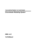
2.3.2 Physical and computational space coordinates
In the literature, bathymetry is generally presented as the vertical distance from some horizontal baseline
(often a mean water height) and may be either positive downward or positive upward. The convention used
in ELCOM is an (x,y,z) space that follows the right-hand rule and has z positive in the upward direction
(Figure 1). The user is free to choose any suitable z=0 baseline for the bathymetry as long as positive z
upward is maintained as the convention for measurement. The pre-processor will adjust the user-defined
z=0 baseline to an internal code baseline that is suitable for the ELCOM simulation. For the most part, the
user does not need to know or consider this internal baseline adjustment. However, some
debugging/monitoring output is presented in terms of the code coordinate system rather than the user
coordinate system, so care must be taken in interpreting debugging output that is intended for use by code
developers. The position of physical space origin (x=0, y=0) is set implicitly by the user through the layout of
the bathymetry data in the file bathymetry.dat. This will be covered in more detail below. Physical space
x and y values may not be negative (i.e., the x,y origin must be in a corner of the domain).
Figure 1. Schematic of coordinate system
ELCOM performs its simulation on computational cells of a three-dimensional Cartesian mesh. The user
needs to understand the layout of the mesh so that boundary condition cells can be properly identified. In
the present version of the code, the mesh has uniform spacing in each of the horizontal dimensions (x and
http://www.cwr.uwa.edu.au/~blaval/manual/elcom/elcom_guide/pre.html (2 of 14) [31/8/2000 1:14:00 PM]
Pre-Processor
y) and allows non-uniform spacing in the vertical (z) direction. Figure 2 shows a plan view (x-y plane) of a
lake with a discrete (uniform) Cartesian mesh overlay. The computational domain is divided into "cells",
whose centers are represented in Figure 2 by solid dots. Dashed lines represent the faces between the
cells. Each cell center has an (i,j,k) coordinate that designates its location in discrete computational space.
The i,j,k values are the integer indices of a three-dimensional array. The right-hand rule is used, with (i,j,k)
being non-zero, positive integer values; k=1 is associated with the lower-most cell layer in the domain. The
(i,j) pairs of a horizontal plane represent a matrix, so that by conventional mathematical notation the (1,1)
position is always in the upper left corner. The ‘i’ index is the row index and increases down the page. The ‘j’
index is the column index and increases across the page. The (i,j) indices for corner cells are shown in
Figure 2. For convenience and consistency, the origin (0,0) of the x,y (physical space) coordinates is taken
to be at the (1,1) location in the computational space i,j indices.
Figure 2. Plan view of Cartesian mesh
Using the upper left corner as the origin may initially be confusing to users familiar with mirror-image storage
(used by many graphics programs) where the lower left corner is stored in position i=1,j=1. The problem with
mirror-image storage is that a simple printout of bathymetry data always appears as an upside-down mirror
image of the real world when viewed with a text processor or spreadsheet. The present convention gives the
user a "What You See Is What You Get" view of the bathymetry simply by opening the file with a word
processor or importing into a spreadsheet. This convention has been found to be intuitive for users who are
not graphics experts. However, caution needs to be taken when converting raw bathymetry data from
graphics programs that use a mirror-image standard. Likewise the direction of the positive u (x direction)
velocity is confusing as it is positive down the page.
Figure 3 shows the physical space outline of the lake as the border of the shaded area. The discrete outline
of a lake is shown with a heavy solid line. In developing a bathymetry.dat file for an ELCOM simulation,
the user is required to provide bathymetry values (i.e. vertical distance measured from the user’s z=0
baseline) for each of the cells within the discrete boundary of the lake. The region outside the lake boundary
is defined as the "land" region. In Figure 3, the cell center dots have been replaced with numbers that
represent the distance from the user’s z=0 baseline to the bottom of the lake. In this case, all of the "land"
regions have been given a value of 99. Note that the boundary of the bathymetry data set shown in Figure 3
has land values around the entire boundary. In general, it is required that either a land cell or open boundary
cell is required around the outside of the bathymetry data. For the purposes of the bathymetry.dat file, the
user must provide bathymetry values for all cells in a rectangular array, including those cells that only
contain land. ELCOM will only reserve computational memory for (1) the cells which may contain water, and
(2) the first layer of land cells surrounding the water cells.
http://www.cwr.uwa.edu.au/~blaval/manual/elcom/elcom_guide/pre.html (3 of 14) [31/8/2000 1:14:00 PM]
Pre-Processor
Figure 3. Plan view of bathymetry data
Figure 4 shows an elevation view (in the x-z plane) of a lake with a Cartesian overlay. A continuous,
physical-space lake bottom is shown as a dashed line, with the resulting discrete lake bottom shown in a
solid line. ELCOM computes the bathymetry on the face of each cell (the dashed lines) from user-supplied
bathymetry data at the cell centers (on the solid dots). In this figure, the user z=0 baseline is chosen as the
top of the domain, so that all the bathymetry values should be negative. Note that the k=1 index of (i,j,k)
space corresponds with the lowermost layer, regardless of the user z=0 baseline position.
Figure 4. Elevation view of bathymetry data
http://www.cwr.uwa.edu.au/~blaval/manual/elcom/elcom_guide/pre.html (4 of 14) [31/8/2000 1:14:00 PM]
Pre-Processor
2.3.3 Creating a bathymetry.dat file
An up-to-date copy of bathymetry.dat can be downloaded from Appendix A. This file can be used as a
template for creating your own bathymetry.dat file. The judicious use of extra comment lines and
comments after the keywords, leads to a file that is much more readable. The bathymetry.dat file can be
renamed, but the corresponding name in the run_pre must also be changed. The pre-processor will run
with some items out of order, but the GUI will be unable to process the bathymetry file.
The remainder of this section will detail the use of each keyword in the bathymetry.dat file.
File header
keywords = FILE, VERSION
The first two non-comment lines of the bathymetry.dat file must begin with the keywords FILE and
VERSION. The data following FILE must be the name of the file. The data following VERSION must be
1.1.a (the present version of the bathymetry.dat file). Thus, the first two non-comment lines must
appear as shown:
FILE
bathymetry.dat
VERSION 1.1.a
Description lines
keywords = TITLE, ANALYST, ORGANIZATION, COMMENT
Several keywords are provided to allow the user to put identifying information at the top of the bathymetry
file. This information is printed to the standard output at the start of the run to provide identification of the
debugging output data. The format for the header lines is string keyword, where the string must be a
non-null character array enclosed in single quotations marks. If the string is left blank or not enclosed in
quotes, the pre-processor will crash with a Fortran read error. The user must have only one COMMENT line.
A typical set of header keywords is shown below.
’Lake
’I.M.
’Very
’test
Nowhere’
Underpaid’
Large Company’
run number 1’
TITLE
ANALYST
ORGANIZATION
COMMENT
Overwriting files
keyword = overwrite
This command is now superceeded by the run_pre file.
yes overwrite
no overwrite
Size of input bathymetry data
keywords = x_rows, y_columns, z_layers, n_max
In order to correctly read the bathymetry data from file bathymetry.dat, the user must tell the
pre-processor the size of grid to expect. The value for x_rows is the number of rows in a two dimensional
plan view of the bathymetry (e.g. figure 4). The y_columns is the number of columns in the
two-dimensional plan view. The number of layers in the vertical direction is identified with the keyword
z_layers. The keyword n_max is used to set an estimate of the number of grid cells in the domain that are
required for simulation (i.e. interior points plus the land points in one layer surrounding the interior). For most
simulations, n_max can be set to 0, and the code will start with an estimate of x_rows x y_columns x
z_layers. However, in some cases, this may create a temporary data array larger than can be processed
http://www.cwr.uwa.edu.au/~blaval/manual/elcom/elcom_guide/pre.html (5 of 14) [31/8/2000 1:14:01 PM]
Pre-Processor
using the available memory and the pre-processor will crash. The crash may produce a machine error
message stating "out of memory," or a more enigmatic "segmentation fault". If insufficient memory is
available, the user can estimate the actual number of grid points required for the simulation and rerun the
preprocessor.
102
84
22
0
x_rows
y_columns
z_layers
n_max
Land cells
keyword = land_value
The land region and is designated by a unique bathymetry value (defined using the keyword
"land_value") that is greater than any value found within the lake. The user is free to choose the
land_value as any convenient number that meets this criterion. Thus, if the user chooses a z=0 baseline
at the very top of the domain, the land_value may be set to zero (and all the bathymetry values should be
negative numbers). If the user chooses the bottom of the domain as the z=0 baseline, then the land
value may be any positive number that is greater than the largest number appearing within the lake
boundary (it is usually convenient to use 9999). In this latter case, all the bathymetry values will be positive
numbers. Note that any cell whose bathymetry is not equal to the land value is considered a cell within
the domain — thus typographical errors can produce spurious interior cells of the domain. The user is not
required to have a z=0 baseline within the domain: it may be convenient to use an external reference such
as sea level. This may result in the lowest point in the domain having a positive non-zero bathymetry value.
99 land_value
Open boundary cells
keyword = open_value
Open boundary cells are boundaries with tidal forcing from an adjacent body of water that is not in the
simulation domain. The user-defined bathymetry value that indicates an open boundary cell is defined with
the keyword "open_value."
88 open_value
North vector
keywords = north_x, north_y
The user may create a bathymetry data file with any orientation (i.e. there is no requirement that north be at
the top of the page). Since wind forcing on the free surface requires a direction, the user must designate the
north direction. The north vector is determined as shown in Figure 5 . Note that the north vector is given in
terms of a vector in physical (x,y,z) space, not the discrete (i,j,k) space. Because the origin is in the upper
left corner, a standard "north up" data set has a north vector of (-1, 0).
-1.0 north_x
0.5 north_y
http://www.cwr.uwa.edu.au/~blaval/manual/elcom/elcom_guide/pre.html (6 of 14) [31/8/2000 1:14:01 PM]
Pre-Processor
Figure 5. Calculation of the north vector
Geographic position
keywords = latitude, longitude, altitude
The user provides the geographic position of the simulation domain using the keywords latitude,
longitude and altitude. Longitude and altitude are provided for future use in expanding CWR-Modeller
to provide more complete graphics. Presently they have no effect on the simulation or output and may be
safely set to 0. The latitude is used to provide appropriate Coriolis forcing in the ELCOM simulation. North
latitudes are entered as positive numbers while south latitudes are entered as negative numbers.
-32.0 latitude
0.0
longitude
0.0
altitude
Horizontal grid spacing
keywords = x_grid, y_grid
The present version of ELCOM uses uniform (non-stretched) grid spacing in the x and y direction. Separate
grid spacings are implemented in each horizontal dimension so that dx /= dy is valid. However, the user
should be careful in implementing a solution grid with different dx and dy grid spacings since this can effect
the solution accuracy. The x and y grid spacings are designated with the key words "x_grid" and
"y_grid".
100.0 x_grid
100.0 y_grid
Layer thickness
keyword = dz
In the vertical direction, ELCOM allows the user to design a structure of horizontal layers whose thickness
varies with depth (i.e. dz = f[z]). Note that the layer thickness may not vary with x or y coordinates. In the
bathymetry.dat file, the successive layer thicknesses (in descending order from the top of the domain)
http://www.cwr.uwa.edu.au/~blaval/manual/elcom/elcom_guide/pre.html (7 of 14) [31/8/2000 1:14:01 PM]
Pre-Processor
are designated by the keyword dz. While the user is free to set the dz values in an arbitrary manner, the
accuracy and stability of the simulation method may be effected by the degree of non-uniformity of the
layers. In general, the simulation method will perform best (i.e. with greatest accuracy) using a grid with
uniform dz. For non-uniform dz, the degradation of accuracy is a function of the rate at which the dz
changes. Thus, a grid that has a dz that varies slowly will perform very well, while a grid with abrupt
changes in grid size will be less accurate. For example, Figure 6 shows two possible configurations which
provide vertical resolution of 0.25 metres in the upper portion of a lake and 2.0 metre resolution in the lower
portion. Both use the same number of grid cells, but the dz distribution on the left of Figure 6 will show better
performance.
0.5
0.5
0.5
0.51
0.54
0.58
0.65
0.75
0.90
1.13
1.41
1.65
1.88
2.0
dz
dz
dz
dz
dz
dz
dz
dz
dz
dz
dz
dz
dz
dz
http://www.cwr.uwa.edu.au/~blaval/manual/elcom/elcom_guide/pre.html (8 of 14) [31/8/2000 1:14:01 PM]
Pre-Processor
Figure 6. Vertical grid spacings
Bathymetry values
keywords = BATHYMETRY DATA
The bathymetry values must be presented in the file bathymetry.dat following a line with the two
keywords BATHYMETRY DATA. Each line of bathymetry values must contain exactly y_columns of data
and there must be exactly x_rows of data lines following BATHYMETRY DATA. Each value on the line may
be separated from then next by one or more spaces or tabs. Thus, for a domain with x_rows = 8 and
y_columns = 13, and land_value = 99 (i.e. similar to figure (3), the bathymetry values would be entered
into the bathymetry.dat file as shown:
http://www.cwr.uwa.edu.au/~blaval/manual/elcom/elcom_guide/pre.html (9 of 14) [31/8/2000 1:14:01 PM]
Pre-Processor
BATHYMETRY DATA
99
99
99
99
99
99
99
99
99
99
99
99 99
99
99 -0.7 -0.5
99
99
99
99
99
99
99
99 99
99 -0.4 -1.2 -1.3 -1.1 -1.4 -2.5 -2.7 -3.3 -0.7
99
99 99
99 -1.1 -1.6 -2.2 -3.2 -3.8 -3.9 -4.1 -5.3 -5.7 -5.2 -2.4 99
99 -0.5 -0.8 -1.2 -2.1 -2.2 -2.4 -3.2 -3.3 -4.1 -5.0 -1.8 99
99
99
99
99
99
99
99
99
99 -1.7 -1.2 -0.7 99
99
99
99
99
99
99
99
99
99 -0.7 -0.9 -0.3 99
99
99
99
99
99
99
99
99
99
99
99
99 99
2.4 Setting up the boundary cell set file (bc.dat)
An up-to-date copy of bc.dat can be downloaded from Appendix A.
2.4.1 Introduction
The boundary cell set file designates logical grouping of grid cells over which boundary conditions are
enforced in ELCOM. One set of points may have a river inflow, another set may have a dam offtake, another
set may represent groundwater inflows, etc. Each set of boundary points is defined by a unique reference
number,(used also by ELCOM temporal boundary condition files), type (one of several keywords), title (user
reference only), and a series of cell i,j,k coordinates. This file gives the user complete flexibility in the
assignment of diverse and complex boundary conditions around a three-dimensional topography.
2.4.2 Boundary cell set categories
The keywords for the boundary cell sets fall into six categories, defined asfollows:
land
Cell boundary which is considered to be land, on which a Dirichlet "no-slip" condition is imposed on
all components of the velocity, and a Neumann "zero-gradient" condition is imposed on transported
scalars.
slip
Cell boundary which is considered to be land, but on which the velocity components tangential to
the boundary have a Neumann "free-slip" condition applied, while the normal component of the
velocity is a Dirichlet "no-flux" condition (this may be thought of more precisely as normal Dirichlet,
tangential Neumann, or NDTN). A Neumann "zero-gradient" condition is imposed on transported
scalars.
flow
Cell boundary through which an inflow or outflow will be imposed as a Dirichlet "fixed velocity"
condition. This also enforces a Dirichlet condition on transported scalars.
section
Cell boundary which is grouped into a set for application of an environmental forcing or scalar
forcing boundary condition, but does not change the underlying form of the velocity boundary
condition (e.g. the free surface may be divided into sections over which different wind conditions
may be enforced — the type velocity boundary condition is not changed, but its magnitude is
adjusted on different
open
Cell boundary which is "open" to inflows and outflows from another body of water where the velocity
is not fixed a priori (i.e. not a Dirchlet boundary) but is a function of the baroclinic and barotropic
forcing near the boundary (presently not implemented).
interior
An interior cell on which a source or sink of mass or tracer is enforced, e.g. a sewage outfall or
drinking water offtake (presently not implemented).
A boundary cell set consists of a collection of cell faces that are the boundaries between interior cells and
http://www.cwr.uwa.edu.au/~blaval/manual/elcom/elcom_guide/pre.html (10 of 14) [31/8/2000 1:14:01 PM]
Pre-Processor
land cells. The land boundary condition is the default for all faces of cells identified by the land_value in
the bathymetry.dat file and for all boundary cell faces below the bathymetry data. As such, the user will
rarely need to use a land boundary condition in the bc.dat file. For a lake without any inflows, outflows or
special boundary conditions, the bc.dat file need not be present.
2.4.3 Boundary cell set face direction
The cell faces of the boundaries are identified by the (i,j,k) coordinates of the interior cell and the direction
from the cell center to the boundary. The conventions used are as follows:
xp
the y-z cell face in the positive x direction from the cell center
yp
the x-z cell face in the positive y direction from the cell center
xm
the y-z cell face in the negative x direction from the cell center
ym
the x-z cell face in the negative y direction from the cell center
top
the x-y cell face above the
all_sides
all possible side boundary faces (i.e. all y-z and x-z faces)
all
all possible side boundary faces plus the bottom boundary
2.4.4 Boundary cell set keywords
The keywords used to identify boundary cell sets are a concatenation of the categories and the face
direction. The valid keywords are listed below:
Boundary Cell Set Keywords
land_xp
land_xm
land_yp
land_ym
land_bottom
land_all_sides
land_all
flow_xp
flow_xm
flow_yp
flow_ym
flow_bottom
flow_all_sides
flow_all
slip_xp
slip_xm
slip_yp
slip_ym
slip_bottom
slip_all_sides
slip_all
section_xp
section_xm
section_yp
section_ym
section_bottom
section_all_sides
section_all
section_top
interior (not
implemented)
open (not
implemented)
2.4.5 Organization of the boundary cell set file (bc.dat)
At the top of the boundary cell set file (bc.dat) the user may put any number of comment lines. Each
comment line must be started with an exclamation point (!) and have at least 3 items on the line (i.e. two
words or numbers separated from the exclamation point and each other by a spaces or tabs). After the initial
comments, the boundary cell set file consists of a series of definitions of boundary sets. Each set consists of
a set identification line followed by one or more lines of cell definitions. Each line must have three items on it
or the pre-processor will crash with a Fortran file read error. Blank lines are not allowed in the boundary cell
set file.
http://www.cwr.uwa.edu.au/~blaval/manual/elcom/elcom_guide/pre.html (11 of 14) [31/8/2000 1:14:02 PM]
Pre-Processor
Each set identification line is of the form: integer keyword title. The first item, integer, is a
reference number for the boundary cell set that is used in preparing temporal boundary condition data files
for the ELCOM simulation run (see section 3.5). Each boundary cell set must have a unique integer
reference number. The keyword is one of the valid keywords listed in table 14. The title is a
user-designated name for the boundary condition set. The title may have more than one word, although
only the first word will be used by the code. After the set identification line, there will be one or more lines of
cell definitions. A cell definition consists of three sets of number in the general form istart:iend
jstart:jend kstart:kend. The i, j, and k are integer values of the cell positions in space for a rectangular
box of cells on which the relevant boundary cell keyword will be applied. For example, a simple boundary
cell set definition might be
107 flow_xp river_inflow
3:10
4:5
10:14
The preprocessor would designate as a single set, all positive x boundaries in the range 3 <= i <= 10 and 4
<= j <= 5 and 10 <= k <= 14. A boundary cell set may have multiple lines of cell definitions:
13 flow_bottom
5:10
5:10
3:8
groundwater_inflow
1:5
10:14
7:11
10:14
12:17
1:5
Note that each number pair in a cell definition must be in increasing order.
There are two simpler cases for implementing boundary cell sets (1) where i,j or k is a single value rather
than a range, (2) where all possible values in i,j or k are to be included. In the former case, only a single
number needs to be provided (rather than a pair), in the latter case, only the colon (:) needs to be listed. For
example, the cell set for an inflow boundary along a flat side where j = 2 might be written as:
2791 flow_ym river_inflow
3:15
2
:
This would group all the possible y-minus cell faces for cells at any k level, where j = 2 and i is bounded by 3
and 15. This generalizes such that a boundary cell set may be written as
214 slip_all freeslip_domain
:
:
:
which enforces a free-slip boundary condition on all boundary faces (sides and bottom) of the domain.
There is no error cross-checking within the pre-processor for cell faces which have been defined as
belonging to more than one boundary cell set. In some cases, multiple definitions may be desirable. For
example, one might define a river inflow which covers the entire depth of the river for purposes of the
velocity boundary condition; and then define a separate section at the bottom of the river that is used to
place a tracer. The bc.dat file might then contain
2791 flow_ym
3:15
73
section_ym
3:15
river_inflow
2
:
tracer_inflow
2
1:5
In other cases, multiple set definitions for a particular face can produce unintended results. For example, if
we define an inflow boundary and a global definition of free-slip boundaries on all the cells:
2791 flow_ym
3:15
214 slip_all
:
river_inflow
2
:
freeslip_domain
:
:
http://www.cwr.uwa.edu.au/~blaval/manual/elcom/elcom_guide/pre.html (12 of 14) [31/8/2000 1:14:02 PM]
Pre-Processor
We then find that the cells (3:15, 2, : ) get defined both with imposed velocity (Dirichlet) boundary conditions
and free-slip (normal-Dirichlet, tangential-Neumann) boundary conditions. Obviously this is inconsistent and
the flow simulation cannot enforce both boundary conditions. Checking for which combinations of multiple
definitions are consistent and which are not is an error capturing routine that is not yet implemented. Thus,
the above boundary cell sets would be processed and provided to ELCOM. Within ELCOM, only one of the
two boundary conditions will actually be enforced, but one cannot tell a priori which boundary condition it will
be without detailed examination of source code. Note that the order the items are defined may affect the
operation of an inconsistent definition. Thus if the above inconsistent definition were reversed and written
as:
214 slip_all freeslip_domain
:
:
:
2791 flow_ym river_inflow
3:15
2:
The results in ELCOM may be different than the previous implementation — they would be wrong in a
different manner. As a general rule, the user should not provide multiple definitions of velocity boundary
conditions on a single cell face. The land, flow and slip keywords all effect the type of velocity boundary
condition; it is incumbent on the user to be sure that the cell faces defined with these types do not have
multiple definitions.
The following table illustrates a bc.dat file with a few subtle uses of the boundary cell set definitions. A flow
boundary has been declared on the x-minus faces of cells with i=2. Thus, to get free-slip boundary
conditions on all the other face, we use the keyword slip_all for cells with i>2. Then to get free slip on the
y-minus and y-plus faces at i=2 requires two more definitions (These are not inconsistent with the flow_xm
definition since they are on different faces of the same cell). Thi s file also shows the use of the
section_top to segregate the free surface into different sets onto which different wind data can be
enforced.
! - - - ! - bc.dat file
! - comment lines need three items
34 flow_xm
2
75 section_top
:
118 section_top
:
25 slip_all_sides
3:34
26 slip_ym
2:
27 slip_yp
2:
outflow_number_1
:
wind_region_a
1:10
wind_region_b
11:21
free_slip_section
:
:
:
::
free_slip_near_inflow_1
::
free_slip_near_inflow_2
::
Table: Example of boundary cell set file (bc.dat)
2.5 Running the pre-processor with run_pre
An up-to-date copy of run_pre can be downloaded from Appendix A.
The run_pre file is a text file that contains the names and location of user-supplied input files and
pre-processor output files. The pre-processor requires two user-supplied text files: bathymetry.dat and
bc.dat. The former describes the bathymetry of the lake and grid configuration. The latter defines sets of
boundary cells. The pre-processor output consists of two Fortran unformatted (binary) files:
sparsedata.unf and usedata.unf. The former contains information on three-dimensional space and is
used by CWR-Modeller and ELCOM. The latter is used by ELCOM, and contains the one-dimensional
spatial relationships required for the simulation. These files may be renamed, but the user must keep track
of which files are "sparsedata" files and which files are "usedata" files. Once the run_pre file is in the
http://www.cwr.uwa.edu.au/~blaval/manual/elcom/elcom_guide/pre.html (13 of 14) [31/8/2000 1:14:02 PM]
Pre-Processor
directory from which you intend to run the pre-processor and the paths and names of the two input and two
output files are specified in run_pre, then the pre-processor can be run by invoking the name of the
executable, namely:
PRE
Notes
1.
The pre-processor cannot interpolate from a coarse bathymetry to a finer grid or filter from a fine
grid to a coarse grid. The user must preform this task before setting up the bathymetry file.
2.
The pre-processor will correctly operate on on files with any line order of the data:keyword
commands, however the GUI can only process bathymetry.dat file that fit the data order
prescribed in this section.
Continue on to ELCOM
http://www.cwr.uwa.edu.au/~blaval/manual/elcom/elcom_guide/pre.html (14 of 14) [31/8/2000 1:14:02 PM]
http://www.cwr.uwa.edu.au/~blaval/manual/elcom/templates/bathymetry.dat
FILE
bathymetry.dat
VERSION
1.1.a
! -----------------------------------------------------------------------! headers: must be contained in quotes ’ ’.
! ’a very small lake’
TITLE
’I.M. Underpaid’
ANALYST
’Very Large Corporation’
ORGANIZATION
’example file’
COMMENT
! -----------------------------------------------------------------------yes
overwrite files
! -----------------------------------------------------------------------! number of grid cells
! 8
x_rows
13
y_columns
14
z_layers
0
n_max
! -----------------------------------------------------------------------! land and open boundary bathymetry values
! 99
land_value
88
open_value
! -----------------------------------------------------------------------! geographic position
! -4.0
north_x (positive x towards bottom of page)
2.0
north_y (positive y towards right on line)
-32.0
latitude
0.0
longitude
0.0
altitude
! -----------------------------------------------------------------------! grid spacing
! 100.0
x_grid_size
100.0
y_grid_size
!
!
! ----------------------------------------------------------------- !
! - dz vector starting from top going down
!
!
!
0.5
dz top
0.5
dz
0.5
dz
0.54
dz
0.58
dz
0.65
dz
0.75
dz
0.90
dz
1.13
dz
1.41
dz
1.65
dz
1.88
dz
2.0
dz bottom
! -----------------------------------------------------------------------! x in rows (increasing down), y in columns (increasing across)
BATHYMETRY DATA
99
99
99
99
99
99
99
99
99
99
99
99
99
99
99 -0.7 —0.5
99
99
99
99
99
99
99
99
99
99 -0.4 -1.2 -1.3 -1.1 -1.4 -2.5 -2.7 -3.3 -0.7
99
99
99
99 -1.1 -1.6 -2.2 -3.2 -3.8 -3.9 -4.1 -5.3 -5.7 -5.2 -2.4
99
99 -0.5 -0.8 -1.2 -2.1 -2.2 -2.4 -3.2 -3.3 -4.1 -5.0 -1.8
99
99
99
99
99
99
99
99
99
99 -1.7 -1.2 -0.7
99
99
99
99
99
99
99
99
99
99 -0.7 -0.9 -0.3
99
99
99
99
99
99
99
99
99
99
99
99
99
99
http://www.cwr.uwa.edu.au/~blaval/manual/elcom/templates/bathymetry.dat [31/8/2000 1:14:04 PM]
!
!
!
!
!
!
!
!
!
!
!
!
!
!
!
!
!
!
http://www.cwr.uwa.edu.au/~blaval/manual/elcom/templates/bc.dat
!
!
!
!
!
- - - - boundary condition file for
A Very Large Lake
File prepared by I.M. Underpaid - 24.05.00
- - - - -
http://www.cwr.uwa.edu.au/~blaval/manual/elcom/templates/bc.dat [31/8/2000 1:14:04 PM]
http://www.cwr.uwa.edu.au/~blaval/manual/elcom/templates/run_pre
! --------------------------------------------------------------------------- !
!
!
FILE
run_pre
VERSION
1.1.a
!
!
! --------------------------------------------------------------------------- !
! input files
!
!
!
’bathymetry.dat’
BATHYMETRY_FILE
’bc.dat’
BOUNDARY_CONDITION_FILE
!
!
! --------------------------------------------------------------------------- !
! output files
!
!
!
bathout.txt
DATAOUT_FILE
usedata.unf
ELCOM_USEDATA_FILE
sparsedata.unf
ELCOM_SPARSEDATA_FILE
!
!
! --------------------------------------------------------------------------- !
! permission to overwrite existing files
!
!
!
yes
overwrite
!
!
! --------------------------------------------------------------------------- !
http://www.cwr.uwa.edu.au/~blaval/manual/elcom/templates/run_pre [31/8/2000 1:14:05 PM]
ELCOM Operation
3. ELCOM Operation
3.1 Introduction
Running an ELCOM simulation requires the user to provide several types of data: (1) initial conditions, (2)
temporal boundary conditions, (3) configuration parameters, and (4) output control. ELCOM obtains this
data from the user through user-prepared input files, pre-processor prepared input files,
CWR-Modeller-prepared input files, and user-prepared subroutines. A separate user guide is provided for
the use of CWR-Modeller, so this aspect of configuring ELCOM will not be covered in detail within this
document. The following section will describe the types of data that CWR-Modeller is used to set, the files
the user is required to prepare without CWR-Modeller, and the files that will be produced as ELCOM output.
3.2 Files for ELCOM
ELCOM is a command-line executable that communicates with the user through files. To simplify the task of
setting up a simulation run, CWR-Modeller, pre-processor, and makefile have been developed. The
pre-processor creates the files sparsedata.unf and usedata.unf which provide all the geometrical
information for a simulation run. The makefile compiles the source code into an executable (ELCOM).
CWR-Modeller creates the datablock.db file that controls simulation output. The following table provides
a summary of file types, whether their presence is required or optional, the purpose of the file, and
responsibility for preparation of the file. The file names in the courier bold font without brackets are fixed
named files (i.e. the file must be present with exactly this name) . File names such as [data_name].unf
use square brackets to indicate that various names determined by ELCOM or CWR-Modeller may be in the
bracketed section (these are specified in the following sections of this document). File names such as
<datablock>.db use the <> brackets to indicate file names (or sections of names) which the user can set,
either through CWR-Modeller or by changing the file name at the command line.
Files for ELCOM
File Name
Presence
Usage
Preparation
run_elcom
required
configuration control
user
Number of
Files
1
<datablock>.db
optional
output control
CWR-Modeller
1
<environment>.dat
elcom_user.f90
optional
boundary condition
user
10
required
initial conditions
user
1
<elcom_user_*>.f90
optional
forced update
user
no limit
<sparsedata>.unf
required
geometry data
pre-processor
1
<usedata>.unf
required
geometry data
pre-processor
1
<group_name>.unf
[data_name].unf
output
datablock output
ELCOM
no limit
output
3D data type output
ELCOM
no limit
[time_]<save>.unf
output
simulation space output
ELCOM
no limit
<restart_out>.unf
ELCOM
makefile
output
restart file
1
required
optional
executable
compiling and linking
ELCOM
make
[*].f90
optional
source code
none
none
1
1
see
makefile
3.3 Compiling and running ELCOM
If the ELCOM executable (ELCOM) is not available, one must be created by compiling the source code. The
source code consists of all the files listed below, plus any user-prepared files.
http://www.cwr.uwa.edu.au/~blaval/manual/elcom/elcom_guide/elcom_op.html (1 of 16) [31/8/2000 1:14:10 PM]
ELCOM Operation
ELCOM Fortran90 Modules
elcom_bc.f90
elcom_caedym2.f90
elcom_curvilinear.f90
elcom_errors.f90
elcom_free_surface.f90
elcom_heat.f90
elcom_mixing.f90
elcom_no_caedym1.f90
elcom_openbound.f90
elcom_quick.f90
elcom_scalar_ultilities.f90
elcom_solver.f90
elcom_time_step.f90
elcom_user.f90
elcom_utilities.f90
elcom_wind.f90
fd_no_caedym.f90
elcom_caedym1.f90
elcom_cgm_setup.f90
elcom_datablock.f90
elcom_flowbound.f90
elcom_globals.f90
elcom_inputs.f90
elcom_momentum.f90
elcom_no_caedym2.f90
elcom_outputs.f90
elcom_scalar_solve.f90
elcom_setup.f90
elcom_testcase.f90
elcom_update.f90
elcom_user_examples.f90
elcom_velocities.f90
main/elcom_main.o
ELCOM is compiled by typing the command
make
at the command line in the same directory as the source code and the makefile. This executes the
makefile and produces the executable ELCOM. The ELCOM executable file is then installed using the UNIX
syntax:
make install
The ELCOM source code directory can then be cleaned up using the following UNIX command:
make clean
ELCOM is executed at the command line by typing ELCOM (capital letters are required) within the directory
where the run_elcom and all the appropriate input data files are located. The monitoring/debugging output
is sent to the standard output of the computer (the display terminal on most UNIX workstations). Unless the
simulation run is very short, it is recommended that the user redirect the output to a file with a UNIX
execution redirection such as:
ELCOM > run_output
3.4 Simulation modules
ELCOM is organized into simulation modules that can be turned off/on depending on the type of simulation
that is desired. A module is turned off/on by setting the value of control keywords. This is done withing the
run_elcom file. These controls provide a simple method for modifying the simulation. For example: a
boundary condition file can be set up to include both meterological data and inflow data. As a simple test,
the user decides to turn off the inflow. One approach would be to return to the pre-processor, eliminate the
inflow boundary cell set, re-run the pre-processor, then modify the temporal boundary condition file to
remove the inflow data. As a simpler approach, the user need only set iflow = 0, and the inflow data and
boundary cell sets will be ignored.
This section will give a brief overview of the modules within ELCOM and their corresponding keywords which
are set within the run_elcom file.
http://www.cwr.uwa.edu.au/~blaval/manual/elcom/elcom_guide/elcom_op.html (2 of 16) [31/8/2000 1:14:10 PM]
ELCOM Operation
3.4.1 Stratification
Density stratification in ELCOM can be through temperature, salinity, or a combination of the two by using
the controls itemperature and isalinity in combination with idensity = 1. If the user desires,
temperature and salinity can be treated as passive tracers (i.e. eliminating the density term from the
momentum equation) by setting idensity = 0. If temperature and/or salinity are turned on, they must be
initialized throughout the simulation domain through the default_*** controls or the user_init_***
controls and their associated subroutines.
3.4.2 Tracers
Up to 10 passive tracers may be transported in a simulation. They may be initialized in the domain using the
user_init_tracer control and subroutine, or they may flow into the domain through an inflow boundary
cell set using the keywords TRACER_** in a temporal boundary condition file.
3.4.3 Surface thermodynamics
The surface thermodynamics module controls the heat transfer across the free surface. To use this module,
the user is required to provide the following data in temporal boundary condition files: solar radiation, wind
speed, air temperature, relative humidity.
3.4.4 Wind
The wind effects ELCOM simulations in three ways: (1) evaporative cooling in the surface thermodynamics
module, (2) application of a wind stress to the free surface, or (3) application of a wind induced momentum
source to the wind mixed layer. The control iwind only sets the functioning of the wind input. Therefore,
with iwind = 0, any wind value read in temporal boundary condition files will not provide a wind stress
boundary condition, but will be used in the surface thermodynamics module (for iheat_input > 0). With
iwind = 1 or 2, any wind value read in temporal boundary condition files will provide a wind stress
boundary condition or a momentum source to the wind mixed layer. As well, the wind value will be used in
the surface thermodynamics module (for iheat_input > 0).
If the keywords WIND_SPEED and WIND_DIR in the temporal boundary condition files are associated with
the boundary cell set 0 (the entire free surface), then a wind field of uniform speed and direction is applied
across the entire free surface. Alternatively, the user may declare multiple boundary cell sets on the free
surface (using the keyword section_top in the file bc.dat for the preprocessor). The different sections
are given reference numbers in bc.dat, which are then used in the temporal boundary condition files to
identify the WIND_SPEED and WIND_DIR for each section.
3.4.5 Inflow/outflow
Inflow and outflow boundaries must be initially declared in the preprocessor bc.dat file. The user must then
ensure that temporal boundary conditions are provided for the flow rate n in the temporal boundary condition
files. For inflow conditions, all transported scalars must also be given boundary values temporal boundary
condition files. If a transported scalar is not given an inflow value, the inflow volume will have a scalar
concentration of 0.
3.4.6 User initialization
The user is provided with the ability to set up complex initial conditions through the adding code to
subroutines in the elcom_user.f90 file. The subroutines in this file are only called if the appropriate
user_init_*** control in the run_elcom file is non-zero. The stub routines supplied with ELCOM are
designed to be executed with the user_init_*** controls = 1. However, this can be modified by the user
so that different initializations are performed for different values of user_init_*** (see section 4 for more
detail).
http://www.cwr.uwa.edu.au/~blaval/manual/elcom/elcom_guide/elcom_op.html (3 of 16) [31/8/2000 1:14:10 PM]
ELCOM Operation
3.4.7 User update
The user is provided with the ability to design new subroutines for modifying the velocity or any transported
scalars in the simulation. These are invoked through the subroutine user_update in the file
elcom_user.f90. Details of writing code for user-developed subroutines is provided in section 5. This code is
turned on or off with the control user_update in file run_elcom
3.5 Configuration controls
3.5.1 Uniform initial conditions
For simple initial conditions that (1) distribute a scalar temperature or salinity over the entire simulation
volume or (2) provide a flat free surface across the entire domain, the user can set the desired values
through the run_elcom file using keywords of the form default_****. Any default value entered will be
overwritten by the user initialization subroutines (when invoked).
Time step
The time step (keyword = del_t) is the number of seconds that the simulation advances in time for each
simulation step.
Number of steps
The total number of time steps to be computed in the present simulation run is set using the keyword
iter_max in the run_elcom file.
Start date
The start date is entered in CWR Julian Day format which specifies the year and day using a real number
with 7 digits to the left of the decimal place as yyyyddd.ddd. The first 4 digits are the year and the
subsequent 3 digits are the Julian Day . Hours, minutes, seconds are represented as fractions of a day (ie.
1am on January 1st, 2000 is represented as 2000000.041667).
3.5.2 CGM tolerance
The CGM_TOL is the residual at which iteration of the conjugate gradient method (used for the free-surface
solution) is stopped.
3.5.3 Turbulence
ELCOM solves the unsteady Reynolds-averaged Navier-Stokes equations (RANS) with four types of
turbulence closure. The base closure scheme, which is always applied (iclosure = 0) requires the user to
set fixed values for horizontal (h_vis) and vertical (v_vis) eddy viscosity. The base closure scheme is
best applied only in unstratified flows. For stratified flow, the base closure scheme can be supplemented by
unstable mixing (iclosure = 1) algorithms. The unstable mixing algorithm mixes momentum and
transported scalars in vertical cells where an unstable gradient of potential density exists (i.e. Ri < 0.0). For
stratified flows driven by surface wind, the wind-mixed-layer closure scheme with energy transport
(iclosure = 6) is recommended. This approach computes the turbulent kinetic energy due to wind
stirring, convective overturns and wind shear, then uses this to compute vertical mixing. Note that iwind =
2 must be used with iclosure = 6.
3.5.4 Output frequency
Outputs of data that are not controlled by the datablock file are set through the iter_out_*** and
start_output_*** keywords. The former controls the time step interval for providing output, the latter
controls the first step on which output will be provided.
http://www.cwr.uwa.edu.au/~blaval/manual/elcom/elcom_guide/elcom_op.html (4 of 16) [31/8/2000 1:14:10 PM]
ELCOM Operation
3.6 Configuration using file run_elcom
A run_elcom template can be obtained from Appendix A.
ELCOM looks for the file run_elcom in the local directory (where the executable reside) to set the
configuration of the simulation run. In future versions, the run_elcom file will be produced through
CWR-Modeller. The run_elcom configuration file controls execution of optional modules and models within
ELCOM, allowing the user to set the parameters that govern the physical and numerical simulation. The
format of the file is flexible in that lines may occur in any order, and not all items must be present. Comment
lines (preceded by ! ) may occur anywhere in the file. Blank lines are not allowed in the file (the code stops
reading at a blank line). Each line (including comment lines) must have at least two items separated by a
blank space. The comment marker (!) counts as an item, so a valid line is ‘! !’ or ‘! ’, while ‘!!’ (no
space between) is not valid. The general format for the file is a series of lines, with each line listing a user
setting, then a keyword that defines the parameter. A typical run_elcom file can be viewed here. The
individual keywords and settings are explained briefly below:
File headers:
FILE
file name for this file (must be run_elcom)
VERSION
current version of run_elcom file (1.1.a)
TITLE
user title for this run (must be inside single quotes ‘ ’)
ANALYST
user name (must be inside single quotes ‘ ’)
ORGANIZATION
user company name (must be inside single quotes ‘ ’)
COMMENT
user comment — only 1 line (must be inside single quotes ‘ ’)
CASE_KEYWORD
allows user to add code to be executed for a particular simulaton case. Must be a string
without blank spaces enclosed in single quotes.
Simulation module controls
iwind controls the wind module
0 = no wind
1 = wind model 1: wind stress boundary conditions; used only with iclosure = 0 or 1
2 = wind model 2: direct wind momentum input; used only with iclosure = 6 RECOMMENDED
iheat_input controls the surface thermodynamics
0 = no surface thermodynamics
1 = surface thermodynamics model 1
iflow controls inflow/outflow (Dirichlet boundaries) overrides boundary condition files
0 = no inflow/outflow
1 = inflow /outflow model 1
itemperature controls whether temperature is a transported scalar
0 = no temperature simulation
1 = temperature as transported scalar
http://www.cwr.uwa.edu.au/~blaval/manual/elcom/elcom_guide/elcom_op.html (5 of 16) [31/8/2000 1:14:11 PM]
ELCOM Operation
isalinity controls whether salinity is a transported scalar
0 = no salinity in simulation
1 = salinity as a transported scalar
idensity controls whether density (buoyancy term) is included in simulation
0 = no buoyancy term
1 = density computed from UNESCO equation of state and used for buoyancy term
ntracer sets the number of tracers which can be transported in a simulation
0 = no tracers
1 to 10 = number of tracers initialized in user_init_tracer or supplied through inflows or
user_update
ICAEDYM controls whether the CAEDYM water quality module is used
0 = CAEDYM off
1 = CAEDYM on
icoriolis controls whether or not the latitude (from bathymetry.dat) is used to compute a
Coriolis term
0 = Coriolis off
1 = Coriolis on
idatablock controls which version of datablock.db is used
1 = version 1.0
2 = version 1.1
icurvilinear controls function of curvilinear approximation module
0 = curvilinear off
1 = output only
2 = use curvilinear and output
Initialization and update options
irestart use of restart file for initial conditions
0 = do not user restart file
1 = use restart file specified by restart_in_file
user_init_u_vel controls user written subroutine for initializing x velocity
0 = ignore subroutine user_u_init
1 = execute subroutine user_u_init with USER_START_U = 1
user_init_v_vel controls user written subroutine for initializing y velocity
0 = ignore subroutine user_v_init
1 = execute subroutine user_v_init with USER_START_V = 1
user_init_w_vel controls user written subroutine for initializing y velocity
0 = ignore subroutine user_w_init
1 = execute subroutine user_w_init with USER_START_W = 1
user_init_temperature controls user written subroutine for initializing temperature
0 = ignore subroutine user_temperature_init
1 = execute subroutine user_temperature_init with USER_START_TEMPERATURE = 1
user_init_salinity controls user written subroutine for initializing salinity
0 = ignore subroutine user_salinity_init
1 = execute subroutine user_salinity_init with USER_START_SALINITY = 1
user_init_tracer controls user written subroutine for initializing tracer
http://www.cwr.uwa.edu.au/~blaval/manual/elcom/elcom_guide/elcom_op.html (6 of 16) [31/8/2000 1:14:11 PM]
ELCOM Operation
0 = ignore subroutine user_tracer_init
1 = execute subroutine user_trace_init with USER_START_TRACER = 1
user_init_viscosity controls user written subroutine for initializing viscosity
0 = ignore subroutine user_viscosity_init
1 = execute subroutine user_viscosity_init with USER_START_VIS = 1
user_init_height controls user written subroutine for initializing free surface height
0 = ignore subroutine user_height_init
1 = execute subroutine user_height_init with USER_START_HEIGHT = 1
user_init_extinction controls user written subroutine for initializing the light extinction (or
attenuation) coefficient
0 = ignore subroutine user_extinction_init
1 = execute subroutine user_extinction_init with USER_START_EXTINCTION = 1
user_update controls user written subroutine for temporal updating of scalars
0 = ignore subroutine user_update
1 = execute subroutine user_update
Turbulence modeling
iclosure controls the type of closure scheme used
0 = constant eddy viscosity
1 = closure model #1 (constant eddy viscosity plus mixing of statically unstable
stratification)
2 = disabled
3 = disabled
4 = disabled
5 = disabled
6 = wind-mixed layer model including mixing energy transport; must be used with iwind =
2 - RECOMMENDED
vis_u x-dir eddy viscosity (metres2/second)
vis_v y-dir eddy viscosity (metres2/second)
vis_w z-dir eddy viscosity (metres2/second)
vis_u_tracer x-dir eddy viscosity for tracers (metres2/second)
vis_v_tracer y-dir eddy viscosity for tracers (metres2/second)
vis_w_tracer z-dir eddy viscosity for tracers (metres2/second)
vis_u_salt x-dir eddy viscosity for salt (metres2/second)
vis_v_salt y-dir eddy viscosity for salt (metres2/second)
vis_w_salt w-dir eddy viscosity for salt (metres2/second)
vis_u_temperature x-dir eddy viscosity for heat (metres2/second)
vis_v_temperature y-dir eddy viscosity for heat (metres2/second)
vis_w_temperature z-dir eddy viscosity for heat (metres2/second)
prandtl turbulent Prandtl number (diffusion of heat νT/κT)
salt_schmidt turbulent Schmidt number (diffusion of salinity νT/κT)
tracer_schmidt turbulent Schmidt number (diffusion of tracer νT/κT)
Model Settings and Controls
drag_btm_cd drag coefficient on bottom cells
model_grav_damp_x damping of gravity for x baroclinic term
http://www.cwr.uwa.edu.au/~blaval/manual/elcom/elcom_guide/elcom_op.html (7 of 16) [31/8/2000 1:14:11 PM]
ELCOM Operation
model_grav_damp_y damping of gravity for y baroclinic term
Scalar maximum and minimum for debugging
min_temperature
max_temperature
min_salinity
max_salinity
min_tracer1, min_tracer2, ... min_tracer10
max_tracer1, max_tracer2, ... max_tracer10
Debugging controls
debug_check controls level of error checking in code
0 = no error checking
1 = checking for errors, stop on fatal errors
2 = highest level of checking for errors, stop on fatal errors
3 = highest level of checking for errors, stop on warning
debug_print controls level of debugging printout
0 = none
1 = minimal
2 = moderate
10 = extensive
debug_point sparse data index point for debug output
debug_baroclinic_x error trapping
0 = off
1 = on
debug_baroclinic_y error trapping
0 = off
1 = on
Output frequency
iter_out_monitor time step interval for ouput of monitoring data
iter_out_save time step interval for output of saved full simulation data
iter_out_restart time step interval for output of restart data
Output start time
start_output_monitor time step to start providing monitoring data
start_output_save time step to start providing simulation save files
Time controls
start_date_CWR start day in CWR Julian Day format yyyyddd (real)
del_t size of time step (in seconds)
iter_max maximum number of time steps in the simulation
Iterative (conjugate gradient method) solution controls
CGM_TOL Tolerance (residual) for stopping conjugate-gradient solution of free-surface equation.
CGM_MIN Minimum number of iterations that must be computed for the conjugate gradient method
to solve the free-surface (over-rides the CGM_TOL)
CGM_MAX Maximum number of iterations that must be computed for the conjugate gradient method
to solve the free-surface
http://www.cwr.uwa.edu.au/~blaval/manual/elcom/elcom_guide/elcom_op.html (8 of 16) [31/8/2000 1:14:12 PM]
ELCOM Operation
Default (uniformly distributed) values
default_height Default water height (in metres). May be over-ridden by user-prepared
subroutine if user_init_height = 1. Note that default height must be lower than the maximum
height of the domain or an error will occur.
default_salinity Default salinity (in practical salinity units [psu], which is essentially equivalent
to parts per thousand). May be over-ridden by user-prepared subroutine if user_init_salinity
= 1.
default_temperature Default water temperature (in Celsius degrees). May be over-ridden by
user-prepared subroutine if user_init_temperature = 1.
default_wind_speed Default wind speed (in ms-1). May be over-ridden by user-prepared input
file (see following section)
default_wind_direction Default wind direction (in degrees measured counter-clockwise from
North in direction wind is coming from). May be over-ridden by user-prepared input file (see
following section)
default_extinction Default light extinction coefficient (in Celsius degrees). May be over-ridden
by user-prepared subroutine if user_init_extinction = 1.
default_bc Default boundary conditions.
1 = no-slip all
2 = free-slip all
3 = drag all
4 = neumann all
5 = free-slip sides, no-slip bottom
6 = free-slip sides, drag bottom
7 = free-slip sides, neumann bottom
8 = values defined in mixing_elcom.f90
Input file names (require exact file name, including extension)
3D_data_file Name of the file containing the 3D data produced by the pre-processor
(sparsedata.unf)
preprocessor_file Name of the file containing the 1D data (maps) produced by the
pre-processor (usedata.unf).
boundary_condition_file Name(s) of the files containing boundary condition information
CAEDYM_file Name of the file containing CAEDYM configuration information
datablock_file Name of the file containing output datablock configuration (produced by GUI)
File Directories (require quote marks around; note that incomplete quotes can cause code to hang)
infile_dir input files directory (ie. datablock.db, sparsedata.unf, usedata.unf, boundary condition
files)
outfile_txt_dir output *.unf files directory. Unformatted binary output files specified by
datablock.db file.
outfile_txt_dir ELCOM diagnostic ascii format files.
Output files names (do not include extension)
restart_save_file kernel of name used for simulation save file (time stamp and .unf are
appended by ELCOM)
restart_out_file kernel of name used for simulation restart output file ( .unf is appended by
ELCOM)
http://www.cwr.uwa.edu.au/~blaval/manual/elcom/elcom_guide/elcom_op.html (9 of 16) [31/8/2000 1:14:12 PM]
ELCOM Operation
3.7 Input files
3.7.1 sparsedata.unf and usedata.unf
The files sparsedata.unf and usedata.unf are required files for ELCOM. These are the Fortran
unformatted (binary) files produced by the pre-processor. The user may rename these files, but must keep
track of which file is the sparsedata file (keyword = 3D_data_file) and which is the usedata file
(keyword = preprocessor_file). ELCOM will look for the files specified in the run_elcom file. If the
incorrect files are used, the simulation will crash.
3.7.2 Datablock.db
A datablock.db template can be obtained from Appendix A
The file datablock.db is a text file produced by CWR-Modeller, and contains the configuration data used to
set up the users output. The name for this file is specified by the user from CWR-Modeller. Alternatively, the
datablock.db file may be setup manually using a text editor.
A datablock.db file is structured as a series of blocks of instructions. Each block requires an exact
number of lines, with specific instructions on each line. Each line contains a single instruction followed by a
comment. The comment must begin with a "!" character. In manually editing datablock.db files, it is
important to keep in mind that while blocks of instructions may be added or removed, lines within a block
can only be modified, but not removed. The following will discuss the structure of each block of instructions.
3.7.2.1 Datablock Description
The first 4 lines of a datablock.db are the datablock description. In order, they are the block descriptor,
the current datablock version number, the number of output groups, and the number of output sets. Output
groups and sets are described below.
3.7.2.2 Group Description
Following the datablock description are the group description blocks. A group represents a group of data to
be output. A data group is defined as an output filename, datatypes to be output (ie. TEMPERATURE,
SALINITY, etc...), the location within the simulation domain of the points at which data is to be output, and
the time at which data is to be output. If several groups are desired, the group descriptions must follow each
other without breaks between them.
A group description block contains 11 lines, which are as follows:
1. BEGIN GROUP_DESCRIPTION
begin block statement
2. group reference number
an integer labelling the group, this can have any value
3. user label
a name containing no blank spaces labelling the group (used by CWR modeller only)
4. output filename
should include .unf suffix
5. set reference number
an integer corresponding to a description of a set of points at which the data are to be output
(sets will be described after groups)
6. number of datatypes in group
an integer indicating the desired number of datatypes to be output (ie. TEMPERATURE,
SALINITY, etc...)
7. should read .TRUE., do not modify
http://www.cwr.uwa.edu.au/~blaval/manual/elcom/elcom_guide/elcom_op.html (10 of 16) [31/8/2000 1:14:12 PM]
ELCOM Operation
8. output interval
an integer indicating the desired number of timesteps between outputs
9. output start time
an integer indicating which time step to begin outputing data
10. output end time
an integer indicating which time step to stop outputing data, 0 indicates entire run
11. should read 0, do not modify
3.7.2.3 Set Description
A set is a set of points at which data are to be output. This can include a vertical column of points, a
contiguous series of column of points (curtain), a horizontal sheet of points, or any group of points in the
three dimensional domain. The valid set types are
PROFILE
CURTAIN_2D
SHEET_2D
ALL_3D
GENERAL_3D
Profiles and curtains require only the (x,y) locations of the base of each column to describe their location.
Sheets can be referenced to a layer, a height above user datum, a height above bottom, or a height below
the free-surface. ALL_3D simply outputs all points in the domain, and GENERAL_3D at points whos
coordinates are individually specified.
A set description block contains 16 lines, which are as follows:
1. BEGIN SET_DESCRIPTION
begin set statement
2. set reference number
an integer labelling the set, this can have any value
3. user label
a name containing no blank spaces labelling the set (used by CWR modeller
only)
4. type of set
on of the 5 valid set type names described above
5. number of cells in set
for type PROFILE this is the desired number of columns, for type
CURTAIN2D this is the number of columns making up the desired curtain, for
type GENERAL_3D this is the desired number of points, for types SHEET_2D
and ALL_3D this value is 0
6. sheet type
for type SHEET_2D this indicates the SHEET datum, for all other set types
the keyword is NULL. Valid sheet type keywords are:
LAYER horizontal layer referenced as layer number up from bottom
as described in bathymetry.dat file
HEIGHT horizontal layer referenced as vertical distance in metres up
from datum as defined in bathymetry.dat file
BOTTOM two dimensional surface defined as a vertical distance in
metres up from the bottom
SURFACE two dimensional surface defined as a vertical distance
down from the free-surface (note: the location of this sheet will
evolve in time as the free-surface evolves)
FLAT a two dimensional sheet made up of calculated properties in
each water column, the calculation type is specified below
http://www.cwr.uwa.edu.au/~blaval/manual/elcom/elcom_guide/elcom_op.html (11 of 16) [31/8/2000 1:14:13 PM]
ELCOM Operation
7. sheet calc
calculation type for SHEET_2D, for all other set types the keyword is NULL.
Valid sheet calcs keywords are:
NEAREST Assigns each sheet value to the grid value vertically
nearest the specified sheet height. Required for sheet types LAYER,
HEIGHT, BOTTOM, and SURFACE. Not used with sheet type FLAT
MAX Assigns each sheet value to the maximum value in a column.
Used only with sheet type FLAT
MIN Assigns each sheet value to the minimum value in a column.
Used only with sheet type FLAT
AVG Assigns each sheet value to the average value in a column.
Used only with sheet type FLAT
TOTAL Assigns each sheet value to the integrated value in a
column. Used only with sheet type FLAT
8. sheet value
Layer number for sheet type LAYER. Vertical distance in metres for sheet
types HEIGHT, BOTTOM, and SURFACE. 0 for sheet type FLAT.
9-16.
Not implemented, do not modify.
3.7.2.4 Group data types
This block begins with the desired number of data types, followed a listing of the desired data types.
1. BEGIN GROUP_DATA_TYPES
Begin data type description
2. group reference number
An integer referencing the group number defined in the group description
3- data types
One data type descriptor per line. The possible data type descriptors are:
Output Datatype Keywords
U_VELOCITY,
TEMPERATURE,
EXTINCTION_COEF,
TRACER_1,
TRACER_4,
TRACER_7,
TRACER_10,
HEIGHT,
SHEAR,
AUX_1,
AUX_4,
U_VIS,
TRACER_XVIS,
SALT_XVIS,
TEMP_XVIS,
S,
CURVATURE,
GRAPH_X,
WIND_U,
RADIAL,
GRAPH_R,
V_VELOCITY,
SALINITY,
FLUC_PRESSURE,
TRACER_2,
TRACER_5,
TRACER_8,
RI_NUM,
MIX_ENERGY,
AUX_2,
AUX_5,
V_VIS,
TRACER_YVIS,
SALT_YVIS,
TEMP_YVIS,
CELLS,
EPSILON,
GRAPH_Y,
WIND_V,
TANGENT,
GRAPH_S
W_VELOCITY,
DENSITY,
TOTAL_PRESSURE,
TRACER_3,
TRACER_6,
TRACER_9,
AUX_3,
W_VIS,
TRACER_ZVIS,
SALT_ZVIS,
TEMP_ZVI,
NORTH,
LAMBDA,
http://www.cwr.uwa.edu.au/~blaval/manual/elcom/elcom_guide/elcom_op.html (12 of 16) [31/8/2000 1:14:13 PM]
ELCOM Operation
3.7.2.5 Group Time List
This block is required to initialize a time stamp for each group. It requires only two lines as follows:
1. BEGIN GROUP_TIME_LIST
Begin group time list
2. group reference number
An integer referencing the group number defined in the group description
3.7.2.6 Set Cell Data
This block describes the spatial location of each datablock set. The locations are described as row, column,
and/or layer number.
1. BEGIN SET_CELL_DATA
Begin set cell data
2. set reference number
An integer referencing the set number defined in the set description
3- cell locations
This input varies for different set types as follows:
PROFILE Each profile requires a row of input. Each row requires 4
integers: 1) x-row, 2) y-column, 3) 0, 4) 0
CURTAIN_2D Each profile making up the curtain requires a row of
input. Each row requires 4 integers: x-row y-column 0 0
SHEET_2D No Input
ALL_3D No input
GENERAL_3D Each point requires a row of input. Each row requires
3 integers: x-row y-column z-layer
3.7.3 Temporal boundary condition (1D) files
A temporal boundary condition file template can be obtained from Appendix A
The one-dimensional temporal boundary condition files (keyword = boundary_condition_file) are set
up by the user to provide environmental forcing information that changes as a function of time. These files
require a format that consists of four header lines followed by columns of data. The data supplied are values
for particular instants of time that are applied at particular points in space (i.e. over a boundary cell set).
Each column is data of a particular type (defined by a keyword in the header). The first column must be time
in CWR format (yyyyddd.dd). Each row is data at a particular time. The file may have as many comment
lines (preceded by !) at the top of the file as desired. Comment lines within the header data must have as
many items as there are columns (i.e. if there are 3 columns a valid comment line is ! - - ). No comment
lines are allowed within the columns of data. The columns must be completely dense with data (i.e. there
may not be "missing" data such that a row has less data than the number of columns.
The first header line contains one number: the number of data sets (columns) in the boundary condition file
not including the time column.
The second line in the header also contains the number 0, indicating that the CWR time format will be used
in the data below, and the first column in the data file should be a TIME column. Note that the user does not
have to supply boundary condition data at the same time interval that the simulation uses as the
computational time step (del_t): the simulation interpolates (linearly) between the temporal boundary
condition data to find the appropriate data value at an instant in time.
The third line in the header must have an integer for each column. This is the reference number for the
applicable set of boundary cell set (defined in the file bc.dat during the setup of the pre-processor) that
each column of data will be applied to. For example, the example bc.dat file shown here (example
bc.dat at bottom of section 2D) provides three sets of boundary points with reference numbers 34, 75,
118, 25, 26, 27. These numbers are used in the third line of the header to identify the points to which a
http://www.cwr.uwa.edu.au/~blaval/manual/elcom/elcom_guide/elcom_op.html (13 of 16) [31/8/2000 1:14:13 PM]
ELCOM Operation
column of data applies. Note that a given reference number may be used for multiple data columns in
multiple files, so that (for example) inflow volumes and temperatures for a particular set of boundary points
may be supplied in one file, while tracer inflow for the same set of points may be supplied in a different file.
Any temporal data boundary condition applied to the entire free surface (which is not required to be defined
as a boundary cell set in bc.dat) is given a reference number of 0 (zero).
The fourth line in the header contains the keyword that describes the data in the column. The keywords are
limited to a set specifically defined and understood by ELCOM and are listed in the table below.
The remaining lines in the file contain the data for the specified time (or time intervals).
Temporal Boundary Condition Data-types
HEIGHT
m
water height for open boundary condition
INFLOW
m3s-1
inflow volume
OUTLFOW
m3s-1
inflow volume
WIND_SPEED
ms-1
wind speed
WIND_DIR
degrees
wind direction (degrees measured clockwise from north that the wind
comes from)
SOLAR_RAD
Wm2
solar radiation that reaches water surface
ATM_PRESS
Pascals
atmopheric pressure
CLOUDS
fractional cloud cover (non-dimensional number between 0 and 1
inclusive)
REL_HUM
relative humidity(non-dimensional number between 0 and 1 inclusive)
SALINITY
PSU
salinity (practical salinity units which can be treated as parts per
thousand within the numerical resolution of the model)
WTR_DENSITY
kgm3
density of inflowing water
AIR_TEMP
degC
air temperature
WTR_TEMP
degC
water temperature for inflowing water
U_VEL
ms-1
velocity in x-direction NOT_IMPLEMENTED
V_VEL
ms-1
velocity in y-direction NOT_IMPLEMENTED
W_VEL
ms-1
velocity in z-direction NOT_IMPLEMENTED
ANGLE
degrees
inflow/outflow angle (degrees measured clockwise from north the
water is flowing to)
TRACER_1
concentration
tracer input
TRACER_2
concentration
tracer input
TRACER_3
concentration
tracer input
TRACER_4
concentration
tracer input
TRACER_5
concentration
tracer input
TRACER_6
concentration
tracer input
http://www.cwr.uwa.edu.au/~blaval/manual/elcom/elcom_guide/elcom_op.html (14 of 16) [31/8/2000 1:14:14 PM]
ELCOM Operation
TRACER_7
concentration
tracer input
TRACER_8
concentration
tracer input
TRACER_9
concentration
tracer input
TRACER_10
concentration
tracer input
3.8 Non-Uniform Initial Conditions -- elcom_user.f90
Non-uniform initial conditions for certain variables can be set up within the elcom_user.f90 file. As
described in the Compiling ELCOM section, elcom_user.f90 is a module of the ELCOM source code.
Within elcom_user.f90 are a number of subroutines which the user can modify to implement initial
conditions. The elcom_user.f90 file will contain a number of examples which the user can emulate to
create their own initial conditions. A list of the initialization subroutines contained within elcom_user.f90
is given below.
User Initialization Subroutines in ELCOM_user.f90
user_u_init,
user_temperature_init,
user_tracer_init,
user_uvis_init,
user_tracer_xvis_init,
user_salt_xvis_init,
user_temp_xvis_init,
user_v_init,
user_salinity_init,
user_extinction_init,
user_vvis_init,
user_tracer_yvis_init,
user_salt_yvis_init,
user_temp_yvis_init,
user_w_init,
user_height_init,
user_wvis_init,
user_tracer_zvis_init,
user_salt_zvis_init,
user_temp_zvis_init
For a particular subroutine to be used, the appropriate user_init_*** keyword must be set to 1 in the
run_elcom file. Within each initialization subroutine, various possible initial conditions are separated from
each other by a series of IF (CASE_KEYWORD == ’string1’) THEN or ELSEIF (CASE_KEYWORD ==
’string2’) THEN statements. A particular initial condition is implemented by setting the CASE_WORD
equal to the appropriate string variable in the IF logical argument. The CASE_WORD is assigned in the
run_elcom file.
3.9 Output files
3.9.1 Datablock output files
An example of a current run_db2nc file can be found in Appendix A.
The datablock output files are named and configured through the datablock.db file which is configured
either manually or through CWR modeller. ELCOM produces Fortran unformatted (binary) files as specified
by the datablock output configuration. In general, one datablock output file contains one or more data types
(e.g. velocity, temperature) applied to as set of points (chosen through CWR-Modeller) at a specified time
interval. These files can be reprocessed into NETCDF files through CWR-Modeller, or manually using the
command-line program db2nc
The program db2nc is used for converting datablock unformatted by binary files created by ELCOM to
NETCDF files which can then be processed and viewed in a program such as Matlab. The db2nc
executable should be placed either in the working directory or as recommended in the /bin directory which
is in the operating system's search path. db2nc is run through a configuration file called run_db2nc.
The run_db2nc file contains 8 lines as follows:
1. Comment line, up to 64 characters
2. .unf file name and path
3. sparsedata.unf file name and path
http://www.cwr.uwa.edu.au/~blaval/manual/elcom/elcom_guide/elcom_op.html (15 of 16) [31/8/2000 1:14:14 PM]
ELCOM Operation
4. .nc netcdf output file name and path
5. Start time step, -1 for beginning
6. End time step, -1 for end of file
7. Overwriting of .nc file? replace for overwriting, noreplace for no overwriting
8. Output diagnosics to monitor? echo to output to monitor, noecho to not output to monitor
Once the run_db2nc file is correctly configured, db2nc can be executed at the command line by typing:
db2nc run_db2nc
Notes:
●
If you get the path for the sparsedata.unf file wrong in your run_db2nc file, db2nc will still run
through and create a slightly smaller .nc file, complete with correct scalar data, however, all spatial
information (x,y,z, etc) will be assigned a value of zero.
●
The run_db2nc can have any file name, however the correct file name must be invoked at run
time.
●
The run_db2nc can only be configured for one file at a time. For batch processing of several .unf
files, it is recommended that a run_db2nc file be created for each .unf to converted and db2nc
be invoked for each run_db2nc using a batch file.
3.9.2 Save and Restart output files
Save and Restart output files are Fortran unformatted (binary) files that contain run configuration information
used to allow the user to restart ELCOM runs from a certain point. As described in the run_elcom section,
the kernel name and output frequency of save and restart files are defined in the run_elcom file.
The save files are created starting at the time step specified by the value assigned to the run_elcom
keyword start_output_save, and subsquently at intervals defined by iter_out_save. The file name of
the save files begin with the user-specified kernel, given by restart_save_file, appended by a time
stamp, appended by .unf. Note that the time stamp does not currently include the simulation year and
there exists the possibility that save files will be overwritten after a year of simulation time.
The restart files are created at intervals defined by iter_out_restart, starting from the first time step.
Subsequent restart files overwrite existing restart files. The file name of the restart files begin with the
user-specified kernel, given by restart_out_file, appended by .unf. All start and restart files are
written in the outfiles directory specified in the run_elcom file.
To restart an ELCOM simulation using a save or restart file, the user must place a copy of the desired save
or restart file in the infiles directory as specified in the run_elcom file. In the run_elcom file the name of
the desired save or restart file must be assigned to the restart_infile keyword, and keyword
i_restart must be assigned the value 1.
Continue on to templates
http://www.cwr.uwa.edu.au/~blaval/manual/elcom/elcom_guide/elcom_op.html (16 of 16) [31/8/2000 1:14:14 PM]
http://www.cwr.uwa.edu.au/~blaval/manual/elcom/templates/run_elcom
! -------------------------------------------------------------------- !
!
!
FILE
run_elcom
VERSION
1.1.a
!
!
! -------------------------------------------------------------------- !
!
!
’A Very Large Lake’
TITLE
’I.M. Underpaid’
ANALYST
’Centre for Water Research’
ORGANIZATION
’ELCOM guide template’
COMMENT
! -------------------------------------------------------------------- !
! simulation modules (0=OFF,1=ON)
!
!
!
1
iwind
! wind forcing (1=stress, 2=momentum, 3=special)
0
iheat_input
! surface thermodynamics
0
iflow
! inflow/outflow
1
itemperature
! temperature
1
isalinity
! salinity
1
idensity
! density (baroclinic forcing)
0
ntracer
! number of tracers
0
iCAEDYM
! water quality module
0 icoriolis
! turn off/on coriolis forcing
0
icurvilinear
! curvilinear terms 1=output only 2=use & output
2
idatablock
! datablock version control
! -------------------------------------------------------------------- !
! initialization options
!
!
!
0
irestart
! start from restart file (yes=1/no=0)
0
user_init_u_vel ! 1 = use stub routine in elcom_user.f90
0
user_init_v_vel
0
user_init_w_vel
0
user_init_temperature
0
user_init_salinity
0
user_init_tracer
0
user_init_viscosity
0
user_init_height
0
user_init_extinction
0 user_update
’SURFACE_SLOPE’
CASE_KEYWORD
!
!
! -------------------------------------------------------------------- !
! turbulence modeling
! (0=no mixing, 1=static stability mixing, 6=mixed layer)
!
!
0
iclosure
! closure model
!
!
! - bottom drag
!
!
!
1.0e-4 drag_btm_cd
! drag coefficient on bottom cells
!
!
! - eddy viscosities
!
!
!
0.0
vis_u
! x-dir eddy viscosity
0.0
vis_v
! y-dir eddy viscosity
3.0e-3 vis_w
! z-dir vertical viscosity
0.0
vis_x_tracer
! x-dir eddy vis for tracer
0.0
vis_y_tracer
! y-dir eddy vis for tracer
0.0
vis_z_tracer
! z-dir eddy vis for tracer
0.0
vis_x_salt
! x-dir eddy vis for salt
0.0
vis_y_salt
! y-dir eddy vis for salt
0.0
vis_z_salt
! z-dir eddy vis for salt
0.0
vis_x_temp
! x-dir eddy vis for temperature
0.0
vis_y_temp
! y-dir eddy vis for temperature
0.0
vis_z_temp
! z-dir eddy vis for temperature
1.0
prandtl
! turbulent Prandtl number
http://www.cwr.uwa.edu.au/~blaval/manual/elcom/templates/run_elcom (1 of 3) [31/8/2000 1:14:31 PM]
http://www.cwr.uwa.edu.au/~blaval/manual/elcom/templates/run_elcom
1.0
1.0
salt_schmidt
tracer_schmidt
! turbulent salinity Schmidt number
! tracer Schmidt number
!
! -------------------------------------------------------------------- !
! model settings and controls
!
!
!
1.0
model_grav_damp_x ! damping of gravity for x baroclinic term
1.0
model_grav_damp_y ! damping of gravity for y baroclinic term
!
!
! -------------------------------------------------------------------- !
! scalar max and min for debugging
!
!
0
min_temperature
40
max_temperature
0
min_salinity
35
max_salinity
0
min_tracer_1
1.1
max_tracer_1
0
min_tracer_2
1.1
max_tracer_2
0
min_tracer_3
0
max_tracer_3
0
min_tracer_4
0
max_tracer_4
0
min_tracer_5
0
max_tracer_5
0
min_tracer_6
0
max_tracer_6
0
min_tracer_7
0
max_tracer_7
0
min_tracer_8
0
max_tracer_8
0
min_tracer_9
0
max_tracer_9
0
min_tracer_10
0
max_tracer_10
!
!
! -------------------------------------------------------------------- !
! special setup (see elcom_setup.f90)
!
!
0
itest_case
! test case number
0
iflow_special
! special flow setup
!
!
! -------------------------------------------------------------------- !
! debug output controls
!
!
1
debug_check
! level of error checking
2
debug_print
! level of debug printing
0
debug_point
! sparse data index point for debug output
1 debug_baroclinic_x ! error trapping on = 1, off = 0
1 debug_baroclinic_y ! error trapping on = 1, off = 0
!
!
! -------------------------------------------------------------------- !
! frequency of outputs
!
!
10
iter_out_monitor
! monitoring output to screen
2000
iter_out_save
! saving separate restart files
500
iter_out_restart
! overwriting restart output
!
!
! -------------------------------------------------------------------- !
! start of outputs
!
!
1
start_output_monitor
! monitor output to screen
1
start_output_save
! saved restart files
!
!
! -------------------------------------------------------------------- !
http://www.cwr.uwa.edu.au/~blaval/manual/elcom/templates/run_elcom (2 of 3) [31/8/2000 1:14:31 PM]
http://www.cwr.uwa.edu.au/~blaval/manual/elcom/templates/run_elcom
! time controls
!
2000001.0
start_date_cwr ! CWR Julian day
950
del_t
! Time step
100
iter_max
! Number of time steps
!
! -------------------------------------------------------------------! conjugate gradient iteration controls
!
1.e-16 CGM_TOL
! CGM tolerance
30
CGM_MIN
! minimum iterations of CGM
1000
CGM_MAX
! maximum iterations of CGM
!
! -------------------------------------------------------------------! default values (superseded by other inputs)
!
0.5
default_height
0.0
default_salinity
12.5
default_temperature
0.0
default_wind_speed
0.0
default_wind_direction
0.3
default_extinction
0
default_bc
! -------------------------------------------------------------------! input file names (include exact file extension)
!
sparsedata.unf
3D_data_file
usedata.unf
preprocessor_file
met.dat
boundary_condition_file
datablock.db
datablock_file
!
! -------------------------------------------------------------------! file directories (require quote marks around)
! (note that incomplete quotes can cause code to hang)
!
’infiles’
infile_dir
’unffiles’
outfile_unf_dir
’txtfiles’
outfile_txt_dir
!
! -------------------------------------------------------------------! output file names (do not include file extension)
!
save
restart_save_file
restart_final restart_out_file
http://www.cwr.uwa.edu.au/~blaval/manual/elcom/templates/run_elcom (3 of 3) [31/8/2000 1:14:31 PM]
!
!
!
!
!
!
!
!
!
!
!
!
!
!
!
http://www.cwr.uwa.edu.au/~blaval/manual/elcom/templates/datablock.db
DATABLOCK DESCRIPTION FILE
1.1.a
! datablock version
13
! number of output groups
13
! number of output sets
BEGIN GROUP_DESCRIPTION
100
! GUI group reference number
tchain
! user label
tchain.unf
! output filename
100
! GUI set reference number
13
! number of datatypes in group
.TRUE. ! is_interval? logical: true if time step interval is used for
5
! output interval
0
! output start time
0
! output end time, 0 indicates entire run
0
! size of time list, non-zero only if is_interval = .FALSE.
BEGIN GROUP_DESCRIPTION
1
! group reference number
curtain_group1
! user label
curtain1.unf
! output filename
2
! set reference number
4
! number of datatypes in group
.TRUE. ! is_interval? logical: true if time step interval is used for
5
! output interval
0
! output start time
0
! output end time, 0 indicates entire run
0
! size of time list, non-zero only if is_interval = .FALSE.
BEGIN GROUP_DESCRIPTION
3
! group reference number
curtain_group2
! user label
curtain2.unf
! output filename
4
! set reference number
9
! number of datatypes in group
.TRUE. ! is_interval? logical: true if time step interval is used for
5
! output interval
0
! output start time
0
! output end time, 0 indicates entire run
0
! size of time list, non-zero only if is_interval = .FALSE.
BEGIN GROUP_DESCRIPTION
7
! group reference number
all_group
! user label
all3d.unf
! output filename
6
! set reference number
9
! number of datatypes in group
.TRUE. ! is_interval? logical: true if time step interval is used for
5
! output interval
0
! output start time
0
! output end time, 0 indicates entire run
0
! size of time list, non-zero only if is_interval = .FALSE.
BEGIN GROUP_DESCRIPTION
9
! group reference number
general_group
! user label
general3d.unf
! output filename
8
! set reference number
9
! number of datatypes in group
.TRUE. ! is_interval? logical: true if time step interval is used for
5
! output interval
0
! output start time
0
! output end time, 0 indicates entire run
0
! size of time list, non-zero only if is_interval = .FALSE.
BEGIN GROUP_DESCRIPTION
11
! group reference number
sheet1_group
! user label
sheet1.unf
! output filename
10
! set reference number
10
! number of datatypes in group
.TRUE. ! is_interval? logical: true if time step interval is used for
http://www.cwr.uwa.edu.au/~blaval/manual/elcom/templates/datablock.db (1 of 9) [31/8/2000 1:14:33 PM]
output
output
output
output
output
output
http://www.cwr.uwa.edu.au/~blaval/manual/elcom/templates/datablock.db
5
! output interval
0
! output start time
0
! output end time, 0 indicates entire run
0
! size of time list, non-zero only if is_interval = .FALSE.
BEGIN GROUP_DESCRIPTION
13
! group reference number
sheet2_group
! user label
sheet2.unf
! output filename
12
! set reference number
10
! number of datatypes in group
.TRUE. ! is_interval? logical: true if time step interval is used for
5
! output interval
0
! output start time
0
! output end time, 0 indicates entire run
0
! size of time list, non-zero only if is_interval = .FALSE.
BEGIN GROUP_DESCRIPTION
15
! group reference number
sheet3_group
! user label
sheet3.unf
! output filename
14
! set reference number
10
! number of datatypes in group
.TRUE. ! is_interval? logical: true if time step interval is used for
5
! output interval
0
! output start time
0
! output end time, 0 indicates entire run
0
! size of time list, non-zero only if is_interval = .FALSE.
BEGIN GROUP_DESCRIPTION
17
! group reference number
sheet4_group
! user label
sheet4.unf
! output filename
16
! set reference number
10
! number of datatypes in group
.TRUE. ! is_interval? logical: true if time step interval is used for
5
! output interval
0
! output start time
0
! output end time, 0 indicates entire run
0
! size of time list, non-zero only if is_interval = .FALSE.
BEGIN GROUP_DESCRIPTION
19
! group reference number
sheet5_group
! user label
sheet5.unf
! output filename
18
! set reference number
10
! number of datatypes in group
.TRUE. ! is_interval? logical: true if time step interval is used for
5
! output interval
0
! output start time
0
! output end time, 0 indicates entire run
0
! size of time list, non-zero only if is_interval = .FALSE.
BEGIN GROUP_DESCRIPTION
21
! group reference number
sheet6_group
! user label
sheet6.unf
! output filename
20
! set reference number
10
! number of datatypes in group
.TRUE. ! is_interval? logical: true if time step interval is used for
5
! output interval
0
! output start time
0
! output end time, 0 indicates entire run
0
! size of time list, non-zero only if is_interval = .FALSE.
BEGIN GROUP_DESCRIPTION
23
! group reference number
sheet7_group
! user label
sheet7.unf
! output filename
22
! set reference number
10
! number of datatypes in group
.TRUE. ! is_interval? logical: true if time step interval is used for
http://www.cwr.uwa.edu.au/~blaval/manual/elcom/templates/datablock.db (2 of 9) [31/8/2000 1:14:33 PM]
output
output
output
output
output
output
http://www.cwr.uwa.edu.au/~blaval/manual/elcom/templates/datablock.db
5
! output interval
0
! output start time
0
! output end time, 0 indicates entire run
0
! size of time list, non-zero only if is_interval = .FALSE.
BEGIN GROUP_DESCRIPTION
25
! group reference number
sheet8_group
! user label
sheet8.unf
! output filename
24
! set reference number
10
! number of datatypes in group
.TRUE. ! is_interval? logical: true if time step interval is used for output
5
! output interval
0
! output start time
0
! output end time, 0 indicates entire run
0
! size of time list, non-zero only if is_interval = .FALSE.
BEGIN SET_DESCRIPTION
100
! GUI set reference number
tchain ! user label
PROFILE_1D
! type of set
3
! number of cells in set
NULL
! sheet type
NULL
! sheet calc
0.0
! sheet value
NULL
! dynamic name #1
NULL
! dynamic calc #1
NULL
! dynamic direction #1
0.0
! dynamic value #1
NULL
! dynamic name #2
NULL
! dynamic calc #2
NULL
! dynamic direction #2
0.0
! dynamic value #2
BEGIN SET_DESCRIPTION
2
! set reference number
curtain_set
! user label
CURTAIN_2D
! type of set
3
! number of cells in set
NULL
! sheet type
NULL
! sheet calc
0.0
! sheet value
NULL
! dynamic name #1
NULL
! dynamic calc #1
NULL
! dynamic direction #1
0.0
! dynamic value #1
NULL
! dynamic name #2
NULL
! dynamic calc #2
NULL
! dynamic direction #2
0.0
! dynamic value #2
BEGIN SET_DESCRIPTION
4
! set reference number
curtain_set2 ! user label
CURTAIN_2D
! type of set
11
! number of cells in set
NULL
! sheet type
NULL
! sheet calc
0.0
! sheet value
NULL
! dynamic name #1
NULL
! dynamic calc #1
NULL
! dynamic direction #1
0.0
! dynamic value #1
NULL
! dynamic name #2
NULL
! dynamic calc #2
NULL
! dynamic direction #2
0.0
! dynamic value #2
BEGIN SET_DESCRIPTION
6
! set reference number
all_set ! user label
http://www.cwr.uwa.edu.au/~blaval/manual/elcom/templates/datablock.db (3 of 9) [31/8/2000 1:14:33 PM]
http://www.cwr.uwa.edu.au/~blaval/manual/elcom/templates/datablock.db
ALL_3D ! type of set
0
! number of cells in set
NULL
! sheet type
NULL
! sheet calc
0.0
! sheet value
NULL
! dynamic name #1
NULL
! dynamic calc #1
NULL
! dynamic direction #1
0.0
! dynamic value #1
NULL
! dynamic name #2
NULL
! dynamic calc #2
NULL
! dynamic direction #2
0.0
! dynamic value #2
BEGIN SET_DESCRIPTION
8
! set reference number
general_set
! user label
GENERAL_3D
! type of set
4
! number of cells in set
NULL
! sheet type
NULL
! sheet calc
0.0
! sheet value
NULL
! dynamic name #1
NULL
! dynamic calc #1
NULL
! dynamic direction #1
0.0
! dynamic value #1
NULL
! dynamic name #2
NULL
! dynamic calc #2
NULL
! dynamic direction #2
0.0
! dynamic value #2
BEGIN SET_DESCRIPTION
10
! set reference number
sheet1_set
! user label
SHEET_2D
! type of set
0
! number of cells in set
LAYER
! sheet type
NEAREST
! sheet calc
3
! sheet value
NULL
! dynamic name #1
NULL
! dynamic calc #1
NULL
! dynamic direction #1
0.0
! dynamic value #1
NULL
! dynamic name #2
NULL
! dynamic calc #2
NULL
! dynamic direction #2
0.0
! dynamic value #2
BEGIN SET_DESCRIPTION
12
! set reference number
sheet2_set
! user label
SHEET_2D
! type of set
0
! number of cells in set
HEIGHT
! sheet type
NEAREST
! sheet calc
4.5
! sheet value
NULL
! dynamic name #1
NULL
! dynamic calc #1
NULL
! dynamic direction #1
0.0
! dynamic value #1
NULL
! dynamic name #2
NULL
! dynamic calc #2
NULL
! dynamic direction #2
0.0
! dynamic value #2
BEGIN SET_DESCRIPTION
14
! set reference number
sheet3_set
! user label
SHEET_2D
! type of set
0
! number of cells in set
http://www.cwr.uwa.edu.au/~blaval/manual/elcom/templates/datablock.db (4 of 9) [31/8/2000 1:14:33 PM]
http://www.cwr.uwa.edu.au/~blaval/manual/elcom/templates/datablock.db
BOTTOM
! sheet type
NEAREST
! sheet calc
0.5
! sheet value
NULL
! dynamic name #1
NULL
! dynamic calc #1
NULL
! dynamic direction #1
0.0
! dynamic value #1
NULL
! dynamic name #2
NULL
! dynamic calc #2
NULL
! dynamic direction #2
0.0
! dynamic value #2
BEGIN SET_DESCRIPTION
16
! set reference number
sheet4_set
! user label
SHEET_2D
! type of set
0
! number of cells in set
SURFACE
! sheet type
NEAREST
! sheet calc
0.5
! sheet value
NULL
! dynamic name #1
NULL
! dynamic calc #1
NULL
! dynamic direction #1
0.0
! dynamic value #1
NULL
! dynamic name #2
NULL
! dynamic calc #2
NULL
! dynamic direction #2
0.0
! dynamic value #2
BEGIN SET_DESCRIPTION
18
! set reference number
sheet5_set
! user label
SHEET_2D
! type of set
0
! number of cells in set
FLAT
! sheet type
MAX
! sheet calc
0.0
! sheet value
NULL
! dynamic name #1
NULL
! dynamic calc #1
NULL
! dynamic direction #1
0.0
! dynamic value #1
NULL
! dynamic name #2
NULL
! dynamic calc #2
NULL
! dynamic direction #2
0.0
! dynamic value #2
BEGIN SET_DESCRIPTION
20
! set reference number
sheet6_set
! user label
SHEET_2D
! type of set
0
! number of cells in set
FLAT
! sheet type
MIN
! sheet calc
0.0
! sheet value
NULL
! dynamic name #1
NULL
! dynamic calc #1
NULL
! dynamic direction #1
0.0
! dynamic value #1
NULL
! dynamic name #2
NULL
! dynamic calc #2
NULL
! dynamic direction #2
0.0
! dynamic value #2
BEGIN SET_DESCRIPTION
22
! set reference number
sheet7_set
! user label
SHEET_2D
! type of set
0
! number of cells in set
FLAT
! sheet type
AVG
! sheet calc
http://www.cwr.uwa.edu.au/~blaval/manual/elcom/templates/datablock.db (5 of 9) [31/8/2000 1:14:33 PM]
http://www.cwr.uwa.edu.au/~blaval/manual/elcom/templates/datablock.db
0.0
! sheet value
NULL
! dynamic name #1
NULL
! dynamic calc #1
NULL
! dynamic direction #1
0.0
! dynamic value #1
NULL
! dynamic name #2
NULL
! dynamic calc #2
NULL
! dynamic direction #2
0.0
! dynamic value #2
BEGIN SET_DESCRIPTION
24
! set reference number
sheet8_set
! user label
SHEET_2D
! type of set
0
! number of cells in set
FLAT
! sheet type
TOTAL
! sheet calc
0.0
! sheet value
NULL
! dynamic name #1
NULL
! dynamic calc #1
NULL
! dynamic direction #1
0.0
! dynamic value #1
NULL
! dynamic name #2
NULL
! dynamic calc #2
NULL
! dynamic direction #2
0.0
! dynamic value #2
BEGIN GROUP_DATA_TYPES
100
! GUI group reference number
U_VELOCITY
V_VELOCITY
W_VELOCITY
TEMPERATURE
DENSITY
AUX_1
AUX_2
AUX_3
AUX_4
AUX_5
MIX_ENERGY
SHEAR
RI_NUM
BEGIN GROUP_DATA_TYPES
1
! group reference number
U_VELOCITY
V_VELOCITY
W_VELOCITY
U_VIS
BEGIN GROUP_DATA_TYPES
3
! group reference number
U_VELOCITY
V_VELOCITY
W_VELOCITY
SALINITY
TEMPERATURE
DENSITY
TRACER_1
TRACER_2
U_VIS
BEGIN GROUP_DATA_TYPES
7
! group reference number
U_VELOCITY
V_VELOCITY
W_VELOCITY
SALINITY
TEMPERATURE
DENSITY
TRACER_1
http://www.cwr.uwa.edu.au/~blaval/manual/elcom/templates/datablock.db (6 of 9) [31/8/2000 1:14:33 PM]
http://www.cwr.uwa.edu.au/~blaval/manual/elcom/templates/datablock.db
TRACER_2
U_VIS
BEGIN GROUP_DATA_TYPES
9
! group reference
U_VELOCITY
V_VELOCITY
W_VELOCITY
SALINITY
TEMPERATURE
DENSITY
TRACER_1
TRACER_2
U_VIS
BEGIN GROUP_DATA_TYPES
11
! group reference
U_VELOCITY
V_VELOCITY
W_VELOCITY
SALINITY
TEMPERATURE
DENSITY
TRACER_1
TRACER_2
HEIGHT
U_VIS
BEGIN GROUP_DATA_TYPES
13
! group reference
U_VELOCITY
V_VELOCITY
W_VELOCITY
SALINITY
TEMPERATURE
DENSITY
TRACER_1
TRACER_2
HEIGHT
U_VIS
BEGIN GROUP_DATA_TYPES
15
! group reference
U_VELOCITY
V_VELOCITY
W_VELOCITY
SALINITY
TEMPERATURE
DENSITY
TRACER_1
TRACER_2
HEIGHT
U_VIS
BEGIN GROUP_DATA_TYPES
17
! group reference
U_VELOCITY
V_VELOCITY
W_VELOCITY
SALINITY
TEMPERATURE
DENSITY
TRACER_1
TRACER_2
HEIGHT
U_VIS
BEGIN GROUP_DATA_TYPES
19
! group reference
U_VELOCITY
V_VELOCITY
W_VELOCITY
number
number
number
number
number
number
http://www.cwr.uwa.edu.au/~blaval/manual/elcom/templates/datablock.db (7 of 9) [31/8/2000 1:14:33 PM]
http://www.cwr.uwa.edu.au/~blaval/manual/elcom/templates/datablock.db
SALINITY
TEMPERATURE
DENSITY
TRACER_1
TRACER_2
HEIGHT
U_VIS
BEGIN GROUP_DATA_TYPES
21
! group reference number
U_VELOCITY
V_VELOCITY
W_VELOCITY
SALINITY
TEMPERATURE
DENSITY
TRACER_1
TRACER_2
HEIGHT
U_VIS
BEGIN GROUP_DATA_TYPES
23
! group reference number
U_VELOCITY
V_VELOCITY
W_VELOCITY
SALINITY
TEMPERATURE
DENSITY
TRACER_1
TRACER_2
HEIGHT
U_VIS
BEGIN GROUP_DATA_TYPES
25
! group reference number
U_VELOCITY
V_VELOCITY
W_VELOCITY
SALINITY
TEMPERATURE
DENSITY
TRACER_1
TRACER_2
HEIGHT
U_VIS
BEGIN GROUP_TIME_LIST
100
! GUI group reference number
BEGIN GROUP_TIME_LIST
1
! group reference number
BEGIN GROUP_TIME_LIST
3
! group reference number
BEGIN GROUP_TIME_LIST
7
! group reference number
BEGIN GROUP_TIME_LIST
9
! group reference number
BEGIN GROUP_TIME_LIST
11
! group reference number
BEGIN GROUP_TIME_LIST
13
! group reference number
BEGIN GROUP_TIME_LIST
15
! group reference number
BEGIN GROUP_TIME_LIST
17
! group reference number
BEGIN GROUP_TIME_LIST
19
! group reference number
BEGIN GROUP_TIME_LIST
21
! group reference number
BEGIN GROUP_TIME_LIST
http://www.cwr.uwa.edu.au/~blaval/manual/elcom/templates/datablock.db (8 of 9) [31/8/2000 1:14:33 PM]
http://www.cwr.uwa.edu.au/~blaval/manual/elcom/templates/datablock.db
23
! group reference number
BEGIN GROUP_TIME_LIST
25
! group reference number
BEGIN SET_CELL_DATA
100
! GUI set reference number
4 3 0 0
4 6 0 0
4 11 0 0
BEGIN SET_CELL_DATA
2
! set reference number
3 7 0 0
4 7 0 0
5 7 0 0
BEGIN SET_CELL_DATA
4
! set reference number
4 2 0 0
4 3 0 0
4 4 0 0
4 5 0 0
4 6 0 0
4 7 0 0
4 8 0 0
4 9 0 0
4 10 0 0
4 11 0 0
4 12 0 0
BEGIN SET_CELL_DATA
6
! set reference number
BEGIN SET_CELL_DATA
8
! set reference number
4 6 2
4 6 3
4 10 1
4 10 3
BEGIN SET_CELL_DATA
10
! set reference number
BEGIN SET_CELL_DATA
12
! set reference number
BEGIN SET_CELL_DATA
14
! set reference number
BEGIN SET_CELL_DATA
16
! set reference number
BEGIN SET_CELL_DATA
18
! set reference number
BEGIN SET_CELL_DATA
20
! set reference number
BEGIN SET_CELL_DATA
22
! set reference number
BEGIN SET_CELL_DATA
24
! set reference number
http://www.cwr.uwa.edu.au/~blaval/manual/elcom/templates/datablock.db (9 of 9) [31/8/2000 1:14:33 PM]
http://www.cwr.uwa.edu.au/~blaval/manual/elcom/templates/met.dat
!
!
!
!
!
6
0
------------------------------------------------------ - A Very Large Lake
Top hat 5m/s wind
File prepared by I.M. Underpaid - 24.05.00
------------------------------------------------------ - data sets
seconds between data
0
0
0
0
0
0
! ------- ---------- ---------- ---------- ---------- --------TIME
WIND_SPEED
WIND_DIR
SOLAR_RAD
AIR_TEMP
REL_HUM
2000001.00
0
0.0
100.00
20.0
0.94
2000001.15
0
0.0
100.00
20.0
0.94
2000001.50
5
0.0
100.00
20.0
0.94
2000002.00
5
0.0
100.00
20.0
0.94
2000003.10
5
0.0
100.00
20.0
0.94
2000003.55
0
0.0
100.00
20.0
0.94
2000004.00
0
0.0
100.00
20.0
0.94
2000005.00
0
0.0
100.00
20.0
0.94
2000006.00
0
0.0
100.00
20.0
0.94
2000007.00
0
0.0
100.00
20.0
0.94
2000008.00
0
0.0
100.00
20.0
0.94
2000009.00
0
0.0
100.00
20.0
0.94
http://www.cwr.uwa.edu.au/~blaval/manual/elcom/templates/met.dat [31/8/2000 1:15:01 PM]
0
-------CLOUDS
0.20
0.20
0.20
0.20
0.20
0.20
0.20
0.20
0.20
0.20
0.20
0.20
http://www.cwr.uwa.edu.au/~blaval/manual/elcom/templates/run_db2nc
! Curtain translation
../curtain1.unf
../infiles/sparsedata.unf
../ncfiles/curtain1.nc
-1
-1
replace
echo
http://www.cwr.uwa.edu.au/~blaval/manual/elcom/templates/run_db2nc [31/8/2000 1:15:02 PM]
Templates
A. Pre-processor Templates
●
bathymetry.dat
●
bc.dat
●
run_pre
B. ELCOM Templates
●
run_elcom
●
datablock.db
●
temporal boundary conditions
●
run_db2nc
http://www.cwr.uwa.edu.au/~blaval/manual/elcom/elcom_guide/appendix_A.html [31/8/2000 1:15:03 PM]
Contents -- Full
ELCOM User-Guide -- Long Contents
1. Introduction
1.1
1.2
1.3
1.4
The ELCOM model
Implementation language
Outline of a simulation run
Conventions and definitions
2. Pre-processor
2.1 Introduction
2.2 Compiling
2.3 bathymetry.dat
2.3.1 Introduction
2.3.2 Physical and computational space coordinates
2.3.3 Creating a bathymetry.dat file
2.4 bc.dat
2.4.1 Introduction
2.4.2 Boundary cell set categorie
2.4.3 Boundary cell set face direction
2.4.4 Boundary cell set keywords
2.4.5 Organization of the boundary cell set file (bc.dat)
2.5 Running
3. ELCOM
3.1
3.2
3.3
3.4
Introduction
Files for ELCOM
Compiling and running ELCOM
Simulation modules
3.4.1 Stratification
3.4.2 Tracers
3.4.3 Surface thermodynamics
3.4.4 Wind
3.4.5 Inflow/outflow
3.4.6 User initialization
3.4.7 User update
3.5 Configuration controls
3.5.1 Uniform initial conditions
3.5.2 Time step
3.5.3 Number of steps
3.5.4 Start date
3.5.5 CGM tolerance
3.5.6 Turbulence
3.5.7 Output frequency
3.6 Configuration using file run_elcom
3.7 Input files
http://www.cwr.uwa.edu.au/~blaval/manual/elcom/elcom_guide/contents_long.html (1 of 2) [31/8/2000 1:15:08 PM]
Contents -- Full
3.7.1 sparsedata.unf and usedata.unf
3.7.2 Datablock.db
3.7.3 Temporal boundary condition (1D) files
3.8 Non-Uniform Initial Conditions -- elcom_user.f90
3.9 Output files
3.9.1 Datablock output files
3.9.2 Restart output files
3.9.3 Three-dimensional output files
3.9.3 Save output files
Appendices
http://www.cwr.uwa.edu.au/~blaval/manual/elcom/elcom_guide/contents_long.html (2 of 2) [31/8/2000 1:15:08 PM]