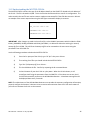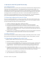
1
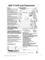
AES 7170 IP Link Receiver (Remote & Local) Supplemental Information 40-7170-SUP Revision 5 July 16, 2015 1 1 Table of Contents 2 Product Description: AES 7170 IP Link System .............................................................................................. 4 2.1 7170 IP Link Transceiver ........................................................................................................................ 5 2.2 ASM Antenna Supervision Module (7170SWR) ..................................................................................... 5 2.3 Antenna ................................................................................................................................................. 6 2.4 Cables and Connectors .......................................................................................................................... 6 2.5 AES 52-0054 Surge Suppressor.............................................................................................................. 6 2.6 Internal Modem..................................................................................................................................... 6 2.7 Typical Unique Installation Tool Requirements .................................................................................... 6 3 Safety Considerations..................................................................................................................................... 7 4 Environmental Considerations ....................................................................................................................... 7 5 Technical Specifications ................................................................................................................................. 7 6 Installation...................................................................................................................................................... 9 7 6.1 7170 IP Link Transceiver Enclosure Mounting ...................................................................................... 9 6.2 Antenna ................................................................................................................................................. 9 6.3 Coaxial Cabling and Connections......................................................................................................... 10 6.4 Surge Suppressor ................................................................................................................................. 10 6.5 Grounding ............................................................................................................................................ 10 Wiring (Electrical Inputs and Outputs) ......................................................................................................... 11 7.1 8 9 10 Terminal Block Connection Details ...................................................................................................... 13 Communications Requirements ................................................................................................................... 14 8.1.1 TCP/IP enabled network ................................................................................................................. 14 8.1.2 Static Intranet/Internet Address (TCP/IP network information) .................................................... 14 8.1.3 Quality of network service .............................................................................................................. 15 8.1.4 Analog phone line (modem capable) .............................................................................................. 15 8.1.5 Console Port access over TCP/IP (for remote locations) ................................................................ 15 Indicators...................................................................................................................................................... 16 9.1 Interface Board LEDs and Speaker ...................................................................................................... 16 9.2 RF / Radio Control Board LEDs ............................................................................................................ 16 Programming and Setup of the 7170 IP Link Transceiver ............................................................................ 18 10.1 Communicating with the 7170 IP Link Transceiver ............................................................................. 19 10.1.1 Connect the PC to the IP Link ..................................................................................................... 19 40-7170-SUP Revision 5 July 16, 2015 2 11 10.1.2 Configure Hyper Terminal to communicate with the 7170 ........................................................ 19 10.1.3 Getting to the IP Link’s Command Prompt ................................................................................. 21 IP Link Configuration Parameters................................................................................................................. 22 11.1 11.1.1 Example of CONF.TXT ................................................................................................................. 23 11.1.2 Lines starting with # .................................................................................................................... 24 11.1.3 IP Link ID ..................................................................................................................................... 24 11.1.4 Cypher code ................................................................................................................................ 24 11.1.5 Security and Encrypt settings ..................................................................................................... 24 11.1.6 Link layer and Ack Mode ............................................................................................................. 24 11.1.7 Receiver TCP/IP Settings ............................................................................................................. 24 11.1.8 Heartbeat Rate............................................................................................................................ 25 11.1.9 Receiver Phone Numbers ........................................................................................................... 25 11.1.10 IP Link TCP/IP Settings ................................................................................................................ 25 11.1.11 Antenna Supervision Module Settings ....................................................................................... 25 11.2 12 13 Understanding the Conf.txt File .......................................................................................................... 22 Understanding the WATTCP.CFG file .................................................................................................. 26 Edit the file CONF.TXT and WATTCP.CFG files ............................................................................................. 27 12.1 Configuration Files ............................................................................................................................... 27 12.2 Retrieving Configuration files from the IP Link.................................................................................... 27 12.3 Edit the CONF.TXT ............................................................................................................................... 27 12.4 Uploading the Configuration files to the IP Link.................................................................................. 27 12.5 Testing the new configuration............................................................................................................. 28 12.6 Set Up Menu and Commands .............................................................................................................. 29 Testing the 7170 IP Link Transceiver ............................................................................................................ 30 13.1 Test Basic Board Functionality............................................................................................................. 30 13.2 Test Local Board Functionality with terminal ...................................................................................... 30 13.3 Testing the Ethernet Network Connection.......................................................................................... 30 13.4 Test RF Signal ....................................................................................................................................... 31 13.5 Test RF Communication Functionality ................................................................................................. 32 AES Service Procedure .......................................................................................................................................... 32 40-7170-SUP Revision 5 July 16, 2015 3 2 Product Description: AES 7170 IP Link System IP Link is an AES-IntelliNet product that uses the Internet to forward received radio signals to a central location. At the central location, an AES-MultiNet receiver is the central controller. IP Link Transceivers are deployed in local and or remote locations to collect AES-IntelliNet radio signals from Subscribers that are then forwarded using the Internet, local network or backup modem, to the central AES-MultiNet Receiver for processing and distribution. The figure below illustrates a typical IP Link system deployment. Figure A Typical AES-IntelliNet Network Configuration The AES 7170 IP Link System is available in a single or dual configuration. In a dual configuration, the second IP Link Transceiver acts as the backup. Each IP Link Transceiver will be configured to monitor and be monitored by a AES-MultiNet receiver. Detection of troubles and switching between primary and secondary is automatic. This product shall be installed in accordance with NFPA 72, NEC, UL 827 and all applicable local codes. 40-7170-SUP Revision 5 July 16, 2015 4 Figure B Typical 7170 IP Link Transceiver Installation All wiring and installation must comply with relevant UL installation standards and local buildings codes. Transformer and its wiring must be protected in conduit and in an AES 1640-ENCL enclosure. Unit must be bonded to Earth Ground via the ground lug on PCB. Customer shall be responsible for design of site-specific conduit detail, including but not limited to the usage of enclosures to house the IP Link and Surge Suppressor for the purpose of protecting transformer wiring in conduit. 2.1 7170 IP Link Transceiver The 7170 IP Link Transceiver acts as a remotely installed hub or receiver that forwards all the signals received from a cluster of AES Subscriber Units to an AES-MultiNet Receiver via a LAN, WAN, the Internet or a backup modem. The AES-MultiNet receiver then forwards the signals to the appropriate system. This allows the customer to expand their geographical market reach without direct radio connectivity to the Central Station Receiver. For AES customers with busy networks, the AES-MultiNet system provides significantly increased capacity for their AES-IntelliNet system without adding a new frequency. It also allows adding a new frequency to a RF congested area. It is housed in a rugged NEMA style enclosure for positioning near the antenna. This assures minimal RF loss from longer coaxial cables. A battery for backup is located in the same enclosure. The battery powers the IP Link Transceiver in event of a power failure. It also, more efficiently provides extra current the transceiver needs when transmitting. As with any AES central station receiver, a Surge Suppressor is required. Flanges are provided for wall mounting. Approximate enclosure size is 14”H x 11.5”W x 6”D. 2.2 ASM Antenna Supervision Module (7170SWR) This module is placed in series with the RF connection between the transceiver and the antenna connector and allows the detection of antenna cut by measuring the SWR. It is powered from the board stack. When the antenna is cut, it issues a signal to the board stack that process it and issues a message to the AES-MultiNet 40-7170-SUP Revision 5 July 16, 2015 5 Receiver. Upon antenna reconnection, a restoral is issued after a pre-defined time has elapsed without any detection of antenna cut. 2.3 Antenna Rugged large antenna to maximize the range of the Base station IP Link Transceiver. Size and gain vary according the installation requirements and radio frequency. Typical size for a UHF antenna is approximately 8 feet in height, with 9db gain. The use of High Gain Antennas is approved for use in a UL installation or for NFPA 72 compliance. 2.4 Cables and Connectors Low-Loss RG-8 (Belden 9913 type) coax cable is supplied with appropriate “N- Type” connectors for maximum performance. 2.5 AES 52-0054 Surge Suppressor A device installed in the coaxial transmission line to help protect components and structure against surges like those produced by lightning. The device dissipates surges to an earth ground that is connected to the device’s mounting bracket. Use only AES part. 2.6 Internal Modem IP Links are equipped with an internal Modem for backup communication when TCP/IP communication is delayed or unavailable. After the IP Link’s initialization process, the modem is tested at a later time using all programmed phone numbers. The time delay to the initial modem test is 12 hours with a 30 minute delay between tests of the individual telephone numbers. During those tests, the Modem LED will be on and the Console Port unavailable. If either number fails to connect to an assigned AES-MultiNet Receiver, it will be retested randomly every 5 to 10 minutes until it passes or the maximum number of 5 attempts is reached. If during normal operation TCP/IP heartbeat fails, the IP Link’s RF goes offline transmitting a “Receiver Not in Service” message. That message will notify other AES-IntelliNet devices to select a secondary IP Link for communicating. The modem is again tested, and if it passes any stored messages are passed to the AES-MultiNet receiver and RF goes back online by transmitting a “Receiver Ready” message. Until the TCP/IP connection returns satisfactorily, communication to the AES-MultiNet receiver will occur using the modem. Sending of Alarm messages via modem are attempted immediately after reception. All other less significant messages may be discarded. The modem, using all phone numbers is tested daily. Interval between daily test attempts is 24 hours plus a random number of minutes up to 30, after the preceding tests pass. This means that the time of day that the daily modem tests occur, randomly advance. This helps to spread out multiple IP Link testing. 2.7 Typical Unique Installation Tool Requirements The primary tools required to install an IP Link Transceiver are as follows. Power or SWR Meter Large Wire Cutters Weatherproof Tape Coax Connector 40-7170-SUP Revision 5 July 16, 2015 6 Crimping Tool RG-8U Coax Strippers Serial Terminal or PC running a terminal program Silicon Sealant 3 Safety Considerations The following items are safety related precautions that you should take into consideration when installing your AES-IntelliNet system. They are for your safety as well as others and the safety of your equipment. Use caution when installing antennas to keep them away from electrical wires which could cause serious injury or death if antenna makes contact with live wires. All equipment must be installed in accordance with National Electric Code, applicable UL Standards and local building codes. Be certain to properly ground the antenna and surge suppressor to help dissipate surges away from equipment and personnel. The grounding of the antenna and surge suppressor is for your safety and the safety of your equipment and should not be neglected. 4 Environmental Considerations The following environmental related suggestions are to help insure an installation that will provide you with a system that will operate at its optimum long into the future. The provided AES 52-0054 surge suppressor should be installed in a weather tight enclosure, such as a UL Listed NEMA4 enclosure. 5 Technical Specifications Listed below are the technical specifications for the 7170 IP Link Transceiver. Transformer Input rating is 16.5 Volts AC at 40/45VA Use only approved transformer Models: AES 1640 Amseco XF-1640 ELK P/N ELK-TRG1640 TDC Power P/N DA-40-16.5 MG Electronics P/N MGT1640 DC Current Draw: 370mA standby, 900mA transmit 7170 DC operating voltage is 12 Volts nominal. Onboard Fuse; Self Resetting / Not User Serviceable Rechargeable Gel Type Batteries Required: 12 Volt, 10 Ampere Hour Low Battery Condition, AC Fail and Charger Trouble are reported to Central Station. Operating Ttempurature Range: 0° to 49° C (32° to 120°F) Storage Temperature Range: -10° to 60° C (14° to 140°F) Relative Humidity Range: 0 to 85% RHC, Non Condensing Transceiver: Standard UHF Frequency Ranges (410-440MHz, 440-470MHz, 470-512MHz) Standard Transceiver RF Output Power: 2 Watts Location : Indoor - Dry Locations 40-7170-SUP Revision 5 July 16, 2015 7 Figure C Enclosure Dimensions 40-7170-SUP Revision 5 July 16, 2015 8 6 Installation The IP Link Transceiver installation site is a critical element of the AES-IntelliNet network. Every installation is unique, taking into account structure, geography and other factors. This section covers elements of the system installation and operation. Read the entire document before proceeding with your installation. Read the Manual and any other provided documents. Study each component to understand its mounting and installation characteristics. Decide how each component be will be installed in your facility. Proceed with the installation in a manner that serves your needs best. Test your installation as outlined in this manual. 6.1 7170 IP Link Transceiver Enclosure Mounting Mount the enclosure on a permanent surface such as a plywood backboard attached to a wall. Locate it so that the coax runs to the antenna without tight bending, kinking or producing strain on the coax and its connectors. Use mounting hardware of appropriate size to support the weight of the enclosure. 6.2 Antenna It is a requirement in a commercial operation when growing a network to cover a large area. For a professional installation, you can install the major components, run the required cables, and then retain a qualified radio technician to perform the RF portion of the installation: 1- Antenna, Mounts and connectors 2- All RF Connectors /Terminations 3- RF Lightning Suppressor / Grounding 4- Final check to assure that your installation is getting maximum performance. Contact the radio technician BEFORE you begin any part of the installation, which is a mix of science and art. Radio signal distance is in part related to the height of the antenna. Select an antenna height that clears all or as many obstructions as possible. If mounting on the side of a metal tower, you should try to place the antenna at least 5 feet off the tower if possible with 2-½ feet off the tower as the absolute minimum. The AES Technical Support team maintains a Knowledgebase with information useful in the installation of antenna, coax IP Links and other AES products. If you don’t have an ‘www.aes-corp.com’ website home page Dealer Login already, it is recommended that you submit a request for portal access and take advantage of this informational tool. Please contact AES Technical Support for details and connection options at (800) 2376387, Option 4 or support@aes-intellinet.com. 40-7170-SUP Revision 5 July 16, 2015 9 6.3 Coaxial Cabling and Connections The length of the coaxial cable is important. Coax causes loss of signal, the longer the coax the greater the loss. You do not want to sacrifice signal loss for antenna height that is not necessary. Ideally, select an antenna height and the 7170 IP Link Transceiver location that will use less than 50 feet of coax. If you must exceed 50 feet absolutely do not exceed 75 to 100 feet unless you use a lower loss cable than provided with the standard system. AES provides a Belden 9913 or equivalent which is a lower loss cable than standard RG-8/U. 9913 is specified as about 3 dB per 100 feet at 400 MHz, which means a loss of 50% of power in 100 feet of coax. 1- Terminate the 9913 N-Type connectors at the coax ends that connect to the antenna, and the surge suppressor, (if applicable, make sure it faces the right direction) and to the 7170 IP Link Transceiver. AES pre-installs one connector on the provided spool of coax. Route or pull your coax such that this connector connects to the base of the antenna if possible. 2- Run the ground cable from surge suppressor to a suitable earth ground in accordance with the local building codes. 6.4 Surge Suppressor Install the Surge Suppressor in the coaxial transmission line outside to help keep surges from entering the building. We recommend installing it in a user provided weather tight enclosure or seal it from moisture with user provided sealant or weather sealing tape such as self-fusing tape. 6.5 Grounding Attach a good earth ground to the surge suppressor and the antenna mounting bracket(s). The grounding of the antenna and surge suppressor is for your safety and the safety of your equipment and should not be neglected. 40-7170-SUP Revision 5 July 16, 2015 10 7 Wiring (Electrical Inputs and Outputs) Listed below are the terminals and connectors in the IP Link Transceiver. Each connection is described in detail. All connections need to be completed before the IP Link Transceiver will be fully functional. Connections on the Interface Board. This is the 2nd board up from the bottom. J2 (16.5VAC) – AC Input. Attach the provided 16.5 VAC 40/45 VA source to this terminal. Use min. 18 Ga., wiring between transformer and J2 AC Input. Telephone – Attach to the phone system for proper line seizure functionality via an RJ-31X jack, using minimum 26 AWG wire. This is used for modem backup communication to IP Link Server. This line must be protected with a UL Listed 497A Secondary Protector. The modem feature has not been evaluated by UL. Ethernet Jack – Attach to the LAN or WAN that connects to the IP Link Server. Use standard CAT-5 Ethernet cable. This line must be protected with a UL Listed 497B Secondary Protector. Console Port – dB-9 Serial port used to program and configure the IP Link’s parameters. Use standard serial cable appropriate for terminal being used. Connections on Radio Control Board. This is the bottom Board. It is an AES 7001 PCB. Radio Transceiver Cable – Connect the dB-9 male connector on the end of this cable to the dB-9 female connector on the radio transceiver. Figure D Illustration of IP Link Transceiver PCB Stack NOTE: Do Not Power Up The IP Link Transceiver Until An AES-MultiNet Receiver Is On-line And Ready For This Unit To Attempt To Connect. 40-7170-SUP Revision 5 July 16, 2015 11 Figure E Enclosure Inside Door Label 40-7170-SUP Revision 5 July 16, 2015 12 7.1 Terminal Block Connection Details The Power Connector terminal block is shown in the figure below. Connect your 16.5 VAC transformer to the designated terminals. DO NOT apply power to these until the AES-MultiNet Receiver is set up and you are ready to proceed with configuration of this Unit. Figure F Power Connector The Telephone (TELCO) Connector terminal block is shown in figure below. These terminals should be properly connected to an RJ-31X phone jack to allow for proper line seizer functions. Refer to telephone company documentation. T and R are to Tip and Ring of phone line. T1 and R1 are for Tip and Ring to premise telephones, if any. Figure G Telephone Connections UL Installation Note: When connecting the 7170 IP Link Transceiver’s modem to a telephone line, a UL Listed 497A Secondary Protector is required to be installed on the incoming lines. Installation shall be in accordance with the NEC Article 800, the manufactures installation instructions and in accordance with all local codes. 40-7170-SUP Revision 5 July 16, 2015 13 Figure H RF Control Board, Input Terminal Block The factory installed Enclosure Tamper Switch is connected to terminals (-) and Z4 on the RF Control Board as illustrated above. The factory installed Antenna Supervision Module (ASM) is connected to terminals +12, (-), and Z2 on the RF Control Board as illustrated above. DO NOT USE Z1, Z3, Z5, Z6, Z7, and Z8. Use UL listed 26AWG minimum wire. 8 Communications Requirements This section covers some important topics related to the communication and network systems needed by the IP Links. Reminder: Check out our Knowledgebase available through the ‘aes-corp.com’ website. There are a number of Solutions with network and phone related information. 8.1.1 TCP/IP enabled network The IP Link’s TCP/IP or Ethernet connection must connect to a network that is capable of communicating with the AES-MultiNet receiver. It is beyond the scope of this document to define how to achieve TCP/IP connectivity. Consult an IT specialist and if necessary consult AES Technical Support for details and connection options at (800) 237-6387, Option 4 or support@aes-intellinet.com. This document assumes that this installation is being made at a site that has a TCP/IP connection to the AES-MultiNet Receiver network. 8.1.2 Static Intranet/Internet Address (TCP/IP network information) Your IP Link will need a dedicated or static IP address for the network where it will be connected. By intended design, the IP Link cannot be configured to use dhcp to acquire its addresses. An IP address, network Gateway and Netmask will be needed. The IP address MUST be static, is to say that the dhcp server on the network must not be allowed to give out this specific IP address to any other device dynamically. The Static IP address DOES NOT NEED TO BE A STATIC IP ADDRESS ON THE PUBLIC INTERNET. It is acceptable and preferred that the IP address be an address on the firewall protected local network that allows access to the Internet if the IP Link needs Internet connectivity to access the Receivers. The gateway providing Internet access can be static or dynamic on the Internet. 40-7170-SUP Revision 5 July 16, 2015 14 8.1.3 Quality of network service Speed is not as important as quality or up time. For this reason, we suggest Business Class or Business Grade service. Also, be advised that Residential DSL service frequently does not provide the quality of service required by an IP Link to meet its 24/7/365 required up time. The preferred network design is to have all the AES-MultiNet devices connected to a dedicated unmanaged switch with no workstations included on the dedicated switch that will be used for any other corporate network access. That dedicated switch is then connected to the corporate switch allowing workstations access to the Receivers. Figure I 8.1.4 Analog phone line (modem capable) A phone line will also be used in the event that the TCP/IP connection of a receiver is down to deliver non Check-In and Alarm messages. An RJ31X is required to seize phone line if line is not dedicated. NOTE: A dedicated phone line is not required although the IP Link will call out at least twice a day to do modem tests. If the IP Links and AES-MultiNet receivers are located in close proximity, you may want to consider using a small office or home office PBX or phone simulator. This removes the need to have POTS lines available or dedicated to the devices. Contact AES Support or search our knowledgebase for additional information. 8.1.5 Console Port access over TCP/IP (for remote locations) For remote locations, where access to the IP Link’s serial console port is not convenient, you may want to consider the installation of a Serial to TCP/IP converter to allow remote access to the IP Link configuration console port across the Internet. For details, please contact AES Technical Support at (800) 237-6387, Option 4 or support@aes-intellinet.com. 40-7170-SUP Revision 5 July 16, 2015 15 9 Indicators There are several LED indicators and one speaker in the IP Link transceiver. Below are descriptions of their functions. 9.1 Interface Board LEDs and Speaker SVC (Red LED) – This LED is to indicate the status of the connection to the AES-MultiNet receiver it is configured to communicate with. If the LED is on then the heartbeat signal that is sent to AES-MultiNet Receiver is receiving the proper response in return. If the LED is off, then the IP Link Transceiver is not receiving the proper acknowledge message back in return to it’s heartbeat signal and the IP Link is offline. LNK + ACT (Green & Yellow LEDs) – These LEDs are for indicating the status of the Ethernet link. The LNK LED indicates the status of the Ethernet. When illuminated, the Ethernet port is receiving the Ethernet ‘heartbeat’ and is connected to a live network. If this LED is not illuminated, there is a problem with the Ethernet wiring or the network. The ACT LED indicates activity on the network. The LED will flash when a data packet is received or transmitted. Modem (Red LED) – This LED indicates which serial device is switched to the available serial port. There is one serial port that is shared between the Console Port and the Modem. Only one device can be attached at a time. When the program wants to use the modem it switches the serial port from the Console Port connector to the on-board modem. When this LED is on the modem can be used. When it is off the Console port is active. For this reason, if the port is switched to the Modem in order for the processor to perform communication or modem test functions, commands sent to the serial port through the Console Port Connector, may not get received or cause a response. Modem Testing and availability of Console Port: During the IP Link’s initialization process the modem is tested using both programmed phone numbers. During those tests the Modem LED will be on and the Console Port is unavailable. If there is no active phone line attached, testing may take a prolonged period of time during which the Console Port will be unavailable. Speaker (SP1) – The speaker is controlled by the modem and is used to monitor / troubleshoot the telephone connection. Dial tone, dialing and connection tones can be heard while the IP Link attempts to connect with the designated AES-MultiNet receiver. 9.2 RF / Radio Control Board LEDs These LEDs are the status indicators for the various states and functions of the Controller board. TX (Yellow LED) – This LED indicates that the radio is transmitting. RX (Green LED) – This LED indicates that the radio is detecting an RF transmission. If the IP Link’s radio receiver is subject to RF Interference, this LED will illuminate steady on and remain on for more than 20 seconds. WA (Yellow LED) – A steady on indicates that a radio packet transmission has been attempted and the controller is waiting for an acknowledgement. Blinking indicates the RF communication is off the network. Off is a normal indication. AL (Red LED) – This LED is a status / Troubleshooting indicator. It is currently not in use and is usually on. This LED can be ignored. 40-7170-SUP Revision 5 July 16, 2015 16 NOTE: If the IP Link’s radio receiver is subject to RF Interference, the “RX” LED will stay on continuously (for more than 20 seconds). The IP Link should not be installed in this location until the source of the interference is located and resolved. Intermittent on and off of the RX LED is normal operation. 40-7170-SUP Revision 5 July 16, 2015 17 IF THE 7005I AES-MultiNet Receiver IS NOT CONFIGURED AND ONLINE READY TO ACCEPT SIGNALS FROM THIS UNIT, 10 Programming and Setup of the 7170 IP Link Transceiver THEN STOP! NOTICE TO USERS, INSTALLERS, AUTHORITIES HAVING JURISDICTION, AND OTHER Install and configure the AES-MultiNet receiver First! INVOLVED PARTIES Then Continue Here This product incorporates field-programmable software. In order for the product to comply with the requirements in the Standard for Control Units and Accessories for Fire Alarm Systems, UL 864, certain programming features or options must be limited to specific values or not used at all as indicated below. Program Feature or Option Permitted in UL 864 (Y/N) Possible functional settings Settings permitted in UL 864 TCP/IP Socket timeout Y 12-30 30 Link Layer Y 0-254 Primary IP Link= 0 Secondary IP Link = 0 Others IP Links = 1 not higher than 4 ACK Mode Y PinG Y 0/Normal – 1/Quick Yes / No Set to 1/Quick Yes To configure the IP Link Transceiver, you communicate with it via the Console Serial Port. Use a serial terminal program (Hyper Terminal) to configure the IP Link Transceiver. Using this software allows you to send ASCII character instructions and view the response on the terminal’s display. The IP Link Transceiver has a built in 10BASE-T Ethernet Port incorporated into the system. Part of configuring the IP Link Transceiver includes editing data files that contain ASCII text strings of parameters. Once you have connected to the Console port with a terminal program, you can reset the unit and be presented with an Option to go to a terminal mode that display the DOS command prompt. Commands can be entered at this prompt. 40-7170-SUP Revision 5 July 16, 2015 18 10.1 Communicating with the 7170 IP Link Transceiver These are instructions for configuring the HyperTerminal emulation program. This program be used to directly communicate with the IP Link Transceiver via the Console port to edit essential configuration files. Other Terminal Emulator software can be used. 10.1.1 Connect the PC to the IP Link The Serial cable needed to connect the PC’s Serial port to the Console Port on the IP Link is an RS 232 straight through (not null modem) cable. It is connected between the 7170 “Console” port and the COM port of your PC running a terminal program. 10.1.2 Configure Hyper Terminal to communicate with the 7170 1. Open Hyper Terminal application. 2. Enter a name and choose an icon for this connection. IP Link would be a good choice for a name that you would recognize in the future when needed. Select an icon for the connection and then select OK. Figure J HyperTerminal - Connection Description 40-7170-SUP Revision 5 July 16, 2015 19 3. Do Not enter any Details for the Country/region, Area code or Phone number. Instead, just pull down the “Connect using” and choose your available free Com Port and select OK. 4. Under the Connect using select the Com port that you will be using. Figure K HyperTerminal - Connect To 5. Under Port Settings change: “Bits per second” to 19200. “Data bits:” 8, “Parity:” None “Stop bits:” 1 “Flow control:” NONE. Press OK. 40-7170-SUP Revision 5 July 16, 2015 20 Figure L HyperTerminal - COM Properties 6. HyperTerminal is now configured for use with the 7170 IP Link. Figure M HyperTerminal after configuration 10.1.3 Getting to the IP Link’s Command Prompt Once your terminal program configured , the 7705i AES-MultiNet Receiver is on-line and your 7170 IP Link Transceiver is installed and wired, you are ready to power up the 7170 IP Link Transceiver and begin the configuration. 40-7170-SUP Revision 5 July 16, 2015 21 1. Confirm that an RS 232 Cable is connected between the serial input of the 7170 “Console” and the COM port of your PC running a terminal program. 2. Confirm that the RJ45 Ethernet Cable is connected between your LAN or WAN Network and the Ethernet jack on the IP Link Transceiver. 3. Confirm that the Phone line is connected to the Phone Line jack on the 7170. 4. Connect the backup Battery in the IP Link Transceiver. 5. Connect the AC Power connected to the IP Link Transceiver at J2. 6. Once powered up, startup messages should be displayed on your terminal program screen. 7. During the startup process and when you see the text “AES UIPLink UCMD Version 0.03” press the "X" key to Halt the startup process and access the Terminal prompt. If you miss this window simply press the reset button on the IP Link Interface board (Middle board) and it will restart again. 8. You should get the “B:\>” prompt. 11 IP Link Configuration Parameters 11.1 Understanding the Conf.txt File It is important to understand which fields need to be modified for your specific installation needs. Use any text editor and then save the configuration file. You can use any file name on the PC. When you upload the file, use the target name as conf.txt. NOTE: Do not add spaces or any other comments unless preceded by #. On lines with data, do not add any comments. Comments work only for the whole line, mixed lines with configuration data and comments ARE NOT ALLOWED. Do not change the order of data. Preserve the original CONF.TXT by saving changes using the Save As function, using a new name. 40-7170-SUP Revision 5 July 16, 2015 22 11.1.1 Example of CONF.TXT The IP Link configuration settings are saved in the CONF.TXT file which is stored on the B drive of an IP Link B:\. An explanation of each parameter can be found on the following pages. Some of the parameters will require the consultation of the Network Administrator or IT specialist familiar with your network. IPLINKID:0xAAAA CYPHER:0x1985 SECURITY:1 ENCRYPT:1 LINK_LAYER:0 ACK_MODE:0x83 # Server configuration RECEIVER1:"10.0.6.243" RECEIVER2:"10.0.9.3" RECEIVER3:"10.0.6.61" RECEIVER4:"10.0.9.4" RECEIVER5:"NO RECEIVER" RECEIVER6:"NO RECEIVER" RECEIVER7:"NO RECEIVER" RECEIVER8:"NO RECEIVER" PORT_AT_1:7070 PORT_AT_2:7070 PORT_AT_3:7070 PORT_AT_4:7070 PORT_AT_5:7070 PORT_AT_6:7070 PORT_AT_7:7070 PORT_AT_8:7070 HEARTRATE:5 # If no phone is available, set as "NO MODEM" PHONE1:"NO MODEM" PHONE2:"NO MODEM" PHONE3:"NO MODEM" PHONE4:"NO MODEM" PHONE5:"NO MODEM" PHONE6:"NO MODEM" PHONE7:"NO MODEM" PHONE8:"NO MODEM" MODEMINIT:"ATM2S0=0S91=11S7=50S9=6&Q6&W0" # IPlink TCP/IP settings IPLINK_IPADDRESS:"10.0.6.134" IPLINK_NETMASK:"255.255.0.0" IPLINK_GATEWAY:"10.0.1.7" TCPTIMEOUT:30 ASM_MODULE_PRESENT:0 ASM_ALARM_TO_TAMPER:0 LEDBOARD_PRESENT:0 $CONFCS:1234 40-7170-SUP Revision 5 July 16, 2015 23 11.1.2 Lines starting with # These are comment lines. Any line beginning with the # symbol is a comment line and will not be read as a parameter of the IP Link’s configuration. 11.1.3 IP Link ID This is a unique AES-IntelliNet 4 digit ID or account hexadecimal values between 0001 and FFFF that identifies this IP Link on the AES-IntelliNet RF Network and in the AES-MultiNet Receivers. AES suggests selecting your IP Link ID’s to be easily picked out of a list of Subscriber ID’s. An example is using Hexadecimal characters such as FF01, FF02, AAAA and BBBB or repeating numbers such as 1111 and 2222. This makes recognizing the IP Link ID easier. ID 0000 is not allowed. 11.1.4 Cypher code This is your AES-IntelliNet RF network’s 4 digit Cypher code between 0000 and FFFF. This unique code ties the IP Link to the Subscribers, on the transceiver assigned frequency. Valid numbers are 0 to 9, and A-F (hexadecimal value). Contact Technical Support if this feature is desired. Do not use 0000 as all AES-IntelliNet Subscribers are shipped with this code. 11.1.5 Security and Encrypt settings Do not change these settings, unless instructed by AES. These two parameters should both have a value of 1. 11.1.6 Link layer and Ack Mode These are settings related to the RF network topology. Do not change unless instructed by an AES Technical Support.. Link Layer should be 0 Options for Ack Mode: 0x83 = FAST (default) 0x82 = NORMAL 11.1.7 Receiver TCP/IP Settings These are the IP addresses and Ports of the AES-MultiNet Receivers. These IP addresses would be either a local IP address of the Receiver for local IP Links or a public IP address for remote IP Links to connect to the designated Receiver across the Internet. Depending on your network configuration, the IP address may need to be port forwarded at a firewall to the inside address of the Receiver. Consult with your IT specialist for advice on the best configuration to meet your needs. Parameters are available for each Receiver to have a different TCP/IP Port value in the case that port forwarding is used when one public IP address is used on the firewall for both the Primary and Secondary Receivers. Port forwarding allows you to distinguish Primary or Secondary Receiver traffic by port being accessed, allowing the traffic to be internally routed to the correct Receiver. There should be little danger of these ports being open on the Firewall as the Receiver will only respond to properly encrypted data. 40-7170-SUP Revision 5 July 16, 2015 24 11.1.8 Heartbeat Rate This is the TCP/IP heartbeat rate. Do not change this value. It should be left at 5. This controls how often the IP Link connects to the Receiver to pass and receive messages. 11.1.9 Receiver Phone Numbers These are the phone numbers used by the IP Link to connect to the Receivers when the Ethernet is nonfunctional. When Ethernet is not available and modems are in use for passing messages to the receivers, Check-Ins are discarded and will most likely result in fail to test messages having not received them at the Receiver and Automation. 11.1.10 IP Link TCP/IP Settings IP settings of the IP Link’s IP address, Netmask, and Gateway. Consult with the administrator of your network to determine the correct values. TCP/IP time-out is the number of seconds before a TCP/IP connection attempt is declared a problem and attempts a roll to the other IP address. Depending on the nature of the problem, the roll may be immediate, which is the case with a disconnected cable. It may take up to 30 seconds depending on the stage where the failure occurred. Do not change the TCP/IP time-out unless instructed by AES. 30 is the default. 11.1.11 Antenna Supervision Module Settings This setting instructs the IP Link to the presence of an Antenna Supervision Module (ASM), and that the signals from it should be interpreted and generate messages to the Receiver. It is standard on the IP Link, and should not be changed unless instructed by AES. The ASM is a black metal enclosure about 3x3x1.25 connected inline between the Transceiver and bulkhead coaxial connector. Its purpose is to detect high SWR readings during transmit and activate an internal relay if above the assigned value. ASM alarm to Tamper is a value that instructs the system to translate the detection of a problem by the ASM as a Tamper. If set to 1, the system uses the same Contact ID message as the Enclosure Tamper (E145 C906). Or if set to 0, uses a new contact ID message (E357 C916). The AES-MultiNet Receiver must be capable of processing the new tamper message if set to 0, otherwise no fault messages is generated on ASM activation. If the value of the ASM to Tamper is set to 1 and an ASM activation results in both an E145 and an E357, the value can safely be set to 0. IP Link Tamper message: E145 C906 Antenna Cut message: E357 C916 8.5.11 LED Board (not used on the 7170) The LED board receives commands from the IP Link when the CONF.TXT file has the line [LEDBOARD_PRESENT:1]. When enabled, it will display the status of the IP Link via the LEDs on the LED board. 40-7170-SUP Revision 5 July 16, 2015 25 11.2 Understanding the WATTCP.CFG file The WATTCP.CFG file contains the copy of the IP address data from the CONF.TXT related to the IP address of the IP Link. The file is located in B:\BIN. This is the file that the Ethernet driver uses for its configuration. The values saved in the conf file are used to create or update a new wattcp file if that file does not exist. Below is an example of the screen output when using the DOS Type command to display its contents. B:\BIN\type wattcp.cfg MY_IP=192.168.0.100 GATEWAY=192.168.0.1 NETMASK=255.255.255.0 IMPORTANT: After changes are made in the conf.txt file, to the IPLINK IP parameters which include the fields IPLINK_IPADDRESS, IPLINK_NETMASK and IPLINK_GATEWAY, it is advised to delete the existing (or rename) wattcp.cfg file in B:\BIN. This will force the wattcp.cfg file to be recreated on the next restart using the parameters from the CONF file. Use the following procedure to delete the WATTCP.CFG file: 1) From the B:> prompt of the IP Link, type “dir \bin” then press <Enter>. 2) The resulting list of files you should include the WATTCP.CFG file. 3) Type “del \bin\wattcp.cfg” then <Enter>. 4) This should delete the file. Confirm by repeating the dir command above. 5) Link and is aware of your the IP Link or cycle power. When the IP Link reboots, it will reconfigure itself using the parameters from the CONF file. If the values are correct, the IP Link should successfully connect to the AES-MultiNet Receiver. A heartbeat message should be displayed about every 5 seconds. NOTE: The administrator of the AES-MultiNet Receivers must provide the necessary configuration information, properly configure the Receiver’s Business Units to receive communication from this IP Link and is aware of your intent to activate the IP Link on the network. 40-7170-SUP Revision 5 July 16, 2015 26 12 Edit the file CONF.TXT and WATTCP.CFG files 12.1 Configuration Files With the command mode active, you will be able to upload (send) or download (receive) configuration files to or from the IP Link’s solid-state disk drives. The configuration files were covered in earlier sections. The configuration files to be edited can be from several sources. These include but are not limited to previous IP Link configuration sessions, the Support Web site, direct from AES Technical Support by email or file transfer, manually generated or retrieved from the IP Link’s drives. The files include CONF.TXT and WATTCP.CFG. If these files are ready to be uploaded to the IP Link, you can skip the next step. If you need a template file, you can retrieve/download/receive the files from the IP Link as outlined in the next steps. 12.2 Retrieving Configuration files from the IP Link The IP Link’s integrated single board PC is running a version of DOS. Many common DOS commands can be issued from the command prompt to perform standard DOS functions or run the various programs available. To retrieve the CONF.TXT file from the IP Link follow these steps: 1) At the B:\> prompt type down conf.txt and then press <Enter>. 2) The IP Link is awaiting the XMODEM file transfer request to from the terminal program. 3) Using HyperTerminal; select from the menu in the menu bar; Transfer then Receive File… Select Xmodem for “Use receiving protocol” and Browse… to the location where you want to save the file. Click Receive, enter a filename and click OK. You will be returned to the command prompt, when the Xmodem transfer is complete. 4) Change directory to the B:\BIN directory (CD \BIN<Enter>) and use the same procedure to retrieve the WATTCP.CFG file if you choose to edit that file in the same manner as the CONF file 12.3 Edit the CONF.TXT Use a text editor like Notepad to carefully modify the parameters as described in previous sections. Save the file on your PC with a file name that is descriptive of the changes for instance “IPLink_AAAA_11_23_15.txt”. 12.4 Uploading the Configuration files to the IP Link To upload or send the CONF.TXT file from the PC to the IP Link; follow these steps: 1) At the B:\> prompt type up conf.txt and then press <Enter>. 2) The IP Link is awaiting the XMODEM file transfer request from the terminal program. Be advised: this is a timed function. If the Xmodem transfer is not initiated from the PC within 30 seconds, the UP program will abort. The letter C advances across the screen indicating the progress of the timer. 3) Using HyperTerminal; select from the menu in the menu bar; Transfer then Send File… Select Xmodem for "Protocol" and Browse… to the location where you saved the file. Select the file and click Send. You will be returned to the command prompt, when the Xmodem transfer is complete. 4) Change directory to the B:\BIN directory (CD \BIN<Enter>). 5) Type “del WATTCP.CFG” to delete the old WATTCP.CFG file. 40-7170-SUP Revision 5 July 16, 2015 27 12.5 Testing the new configuration 1) First, connect the Ethernet and phone wires. 2) The new configuration, can be tested by resetting the IP Link, thereby forcing it to reinitialize using the new files. Cycling power is a better method, as all boards will restart. If you are accessing the IP Link by some remote method, configuration that is beyond the scope of this document, and you do not have access the hardware, you can start the IP Link by issuing the command “UCMD” on the command prompt. The start up screen should look something similar to the text below. UCMD UIPLINK -I00001111 -S192.168.0.11 -P7070 –N101 AES UIPLink UCMD Version 0.02 Running UIPLink -v Setting Watchdog 70 Sec Calculating UIPLINK.exe Checksum Please Wait... Bytes Read 512Bytes Read 1024By Done We are UIPLINK.exe with a Chksum of 0xF091, File Size 135040 Press Enter for Menu UIPLink S0.4.4 Startup ChkSum:F091, Size:135040. Heart Rate = 5 Seconds IPlinkID = 00000002 Queued[0], Software Version For Server Initializing TCP/IP Sockets My IP Address is 192.168.0.11 sendRequest(TT) Opening 192.168.0.101 on Port 7070 ServerTime&Date Sync. Thu Jan 06 18:10:46 2005 Radio Node Sent Me:↓ sendQueue sendRequest(TT) ServerTime&Date Sync. Thu Jan 06 18:10:46 2005 40-7170-SUP Revision 5 July 16, 2015 sendRequest(QQC) sendRequest(QQF) 28 12.6 Set Up Menu and Commands During normal operation, when the Modem is not selected for testing or backup communication, press “S” plus <Enter> to access the Setup Menu. Once the Set Up Menu is displayed press a selected highlighted letter and then press <Enter> to access a function. Figure N IP Link Setup Menu The table below lists all the a functions that can be accessed from the Setup Menu. Key Description R Resets the IP Link. There is up to a 70 second delay as the unit waits for the watchdog program to initiate the reset. M Forces a test of the modem. Same as is automatically run at program start and daily. D Displays a scrollable log with the results of the last modem test. W Runs tests on the power supply. Follow prompts on display. C This allows you to check the Cypher (Cipher) Code. You can enter a value and it will tell you if the entered value matched the programmed cypher. Q To Quit menu and return to normal operation. H Presents a menu to select which receiver to connect to. F Initiates a RF transmission for 10 Seconds. 40-7170-SUP Revision 5 July 16, 2015 29 13 Testing the 7170 IP Link Transceiver There are several functions of the IP Link Transceiver that can be tested to confirm that it is operating properly. 13.1 Test Basic Board Functionality The tests in this part are intended to check that there is power to the boards and that they have at least basic functionality. Testing RF Board Local operation. 1. After performing a power up or Radio Reset the RX, WA, and AL LEDs will come on for about one second during the self-test process. 2. Once self-test is complete, the AL LED will come on steady. Testing Interface Board Local operation. The board has two LEDs that indicate the status of the Ethernet link. The LNK LED indicates the status of the Ethernet. When illuminated, the Ethernet Port is receiving the Ethernet ‘heartbeat’ and is connected to a live network. If this LED is not illuminated, there is a problem with the Ethernet wiring or the network. The ACT LED indicates activity on the network. The LED will flash when a data packet is received or transmitted. 1. If the Ethernet port your IP Link Transceiver is correctly attached to another functioning Ethernet port there should be activity on the LNK and/or ACT LEDs as indicated above. 13.2 Test Local Board Functionality with terminal The tests in this part check the interaction between each board and the attached terminal emulator program. A terminal emulator program like HyperTerminal connected to the “Serial Input” Port is required to perform testing of the IP Link Transceiver at the local installed location. Instructions for connecting and configuring a terminal to the IP Link transceiver can be found in Section 10, Programming and Setup of the 7170 IP Link Transceiver. Receiving the output on your terminal’s display confirms most of the basic functionality of the IP Link Transceiver and interaction with all the boards. 13.3 Testing the Ethernet Network Connection If the IP Link is unable to connect to a AES-MultiNet receiver, you may want to perform some basic tests to determine what level if any your network adapter has. The first test is a visual test. There are two Ethernet status LED indicators located in the lower left corner of the IP Link Control board. There may be no physical connection to an active Ethernet port on a switch, if the LNK or Link LED is not on. Use the PING command to test another IP device connection. The ping command is issued from a command prompt, accessed by pressing "X" during boot up, when prompted with "AES UIPLink UCMD Version 0.03", after a reset is initiated. 40-7170-SUP Revision 5 July 16, 2015 30 Ping the Gateway address assigned to this IP Link. If it can't ping the Gateway, the IP Link may not be configured properly. If the AES-MultiNet receiver is on the same LAN, you should be able to get a successful ping response from its IP address AES-MultiNet Receivers accessed across the Internet may not be able to respond to a ping, depending on firewall configurations. Attempt to ping any known IP address on the Internet to test the Internet access. There are many possible. 8.8.8.8 and 8.8.4.4 are two possibilities. These are Google's public DNS servers. Ping other known IP addresses. Be advised, an IP Link is not supposed to respond to a ping request. If it does, there is usually a much longer delay than you would normally expect and many or several failures. Some Examples of using ping: ping 10.0.6.243<Enter> This is the IP address of your 7705i in the network ping 10.0.1.1<Enter> Ping typical gateway in a 10.0.1.xxx network ping 8.8.8.8<Enter> Pings a public Google DNS server 13.4 Test RF Signal Tests in this part are intended to check the transmission line and components for proper operation and problems. This is a very important test and should be performed as soon after power up as feasible. Operating the unit with a faulty transmission line or component could cause damage to electronics in the unit. As a precaution, you could disconnect the dB9 connector from the transceiver inside the IP Link until this test can be performed. To test your IP Link’s RF signal you need to connect a power meter or SWR meter in the coax line to read power. As with other tests you need a terminal connected to the “Serial Input” of the IP Link. 1. While on the normal Heartbeat screen enter the Setup Menu by pressing <S>. 2. Press <F>. 3. When prompted, press <Y>. 4. When prompted for Tone or Pattern, press <T>. 5. During the 10-second transmission record your meter’s reading. 6. An SWR reading of less than 3 to 1 is acceptable. 7. If the reading is greater than 3 to 1, then replace the antenna, coax and or coaxial connectors until the reading falls below the acceptable level. 8. To exit, press <Q> on the Setup Menu. 40-7170-SUP Revision 5 July 16, 2015 31 13.5 Test RF Communication Functionality The easiest method to locally test RF functionality is to have a programmed AES Subscriber unit with 7041 Hand Held Programmer available. Use the “Display Status” function (<Shft> + <F4>) to determine if your subscriber is connected to the network and most importantly that “RT1: #### contains the ID of the IP Link Transceiver and that the Link Layer (Level) and NETCON are as expected. Level should be 1 higher than the Link Layer setting in the IP Link Transceiver. Contact an operator at the location of the AES Supervising IP Link Transceiver Station to confirm that signals are coming in from this IP Link Transceiver. This test of course is also confirming TCP/IP communication or complete end-to-end testing as well. AES Service Procedure Contact AES Corporation at (800) 237-6387 or (978) 535-7310 to receive a Return Authorization Number. Have the AES part number and serial number ready beforehand. Repack equipment in original or equivalent packaging. Inside the box, include contact information (contact name, telephone number, address) and a brief description of the reason for return. Ship authorized RA items freight-prepaid to: Repair Services, RA# AES Corporation 285 Newbury Street Peabody, MA 01960 USA 40-7170-SUP Revision 5 July 16, 2015 (Contact AES for Return Authorization number) 32