1
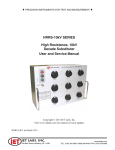
♦ PRECISION INSTRUMENTS FOR TEST AND MEASUREMENT ♦
RTD Series
Precision Resistance
Temperature Detector (RTD)
Simulator
User and Service Manual
Copyright © 2014 IET Labs, Inc.
Visit www.ietlabs.com for manual revision updates
RTD Series-im November 2014
IET LABS, INC.
www.ietlabs.com
Email: info@ietlabs.com
TEL: (516) 334-5959 • FAX: (516) 334-5988
♦ PRECISION INSTRUMENTS FOR TEST AND MEASUREMENT ♦
IET LABS, INC.
www.ietlabs.com
Email: info@ietlabs.com
TEL: (516) 334-5959 • FAX: (516) 334-5988
WARRANTY
We warrant that this product is free from defects in material and workmanship and, when properly used,
will perform in accordance with applicable IET specifications. If within one year after original shipment,
it is found not to meet this standard, it will be repaired or, at the option of IET, replaced at no charge when
returned to IET. Changes in this product not approved by IET or application of voltages or currents greater
than those allowed by the specifications shall void this warranty. IET shall not be liable for any indirect,
special, or consequential damages, even if notice has been given to the possibility of such damages.
THIS WARRANTY IS IN LIEU OF ALL OTHER WARRANTIES, EXPRESSED OR IMPLIED,
INCLUDING BUT NOT LIMITED TO, ANY IMPLIED WARRANTY OF MERCHANTABILITY OR
FITNESS FOR ANY PARTICULAR PURPOSE.
i
WARNING
OBSERVE ALL SAFETY RULES
WHEN WORKING WITH HIGH VOLTAGES OR LINE VOLTAGES.
Dangerous voltages may be present inside this instrument. Do not open the case
Refer servicing to qualified personnel
HIGH VOLTAGES MAY BE PRESENT AT THE TERMINALS OF THIS INSTRUMENT
WHENEVER HAZARDOUS VOLTAGES (> 45 V) ARE USED, TAKE ALL MEASURES TO
AVOID ACCIDENTAL CONTACT WITH ANY LIVE COMPONENTS.
USE MAXIMUM INSULATION AND MINIMIZE THE USE OF BARE
CONDUCTORS WHEN USING THIS INSTRUMENT.
Use extreme caution when working with bare conductors or bus bars.
WHEN WORKING WITH HIGH VOLTAGES, POST WARNING SIGNS AND
KEEP UNREQUIRED PERSONNEL SAFELY AWAY.
CAUTION
DO NOT APPLY ANY VOLTAGES OR CURRENTS TO THE TERMINALS OF THIS
INSTRUMENT IN EXCESS OF THE MAXIMUM LIMITS INDICATED ON
THE FRONT PANEL OR THE OPERATING GUIDE LABEL.
ii
Contents
Chapter 1 Introduction ..............................................................................1
1.1
Introduction ........................................................................................................... 1
Chapter 2 Specifications ...........................................................................2
Specifications ................................................................................................................ 2
Chapter 3 Installation ................................................................................6
3.1
Initial Inspection ................................................................................................... 6
3.2
Installation............................................................................................................. 6
3.3
Repackaging for Shipment .................................................................................... 6
3.4
Storage .................................................................................................................. 6
Chapter 4 Operation ..................................................................................7
4.1
Initial Inspection and Setup .................................................................................. 7
4.2
Connection ............................................................................................................ 7
4.2.1
4.3
General Considerations ............................................................................... 7
Electrical Considerations ...................................................................................... 7
4.3.1 Thermal emf Considerations....................................................................... 7
4.4
Dial Setting ........................................................................................................... 8
4.5
Power Considerations ........................................................................................... 8
4.6
Environmental Conditions .................................................................................... 8
4.7
Switch Conditioning ............................................................................................. 8
4.8
Meter Shunt Applications ..................................................................................... 9
4.9
Kelvin Bridge Applications................................................................................... 9
Chapter 5 Maintenance..............................................................................11
5.1
Maintainability and Reliability ............................................................................. 11
5.2
Preventive Maintenance ........................................................................................ 11
5.3
Calibration............................................................................................................. 11
5.3.1
Calibration Interval ..................................................................................... 11
5.3.2
General Considerations ............................................................................... 12
5.3.3
Required Equipment ................................................................................... 12
5.3.4
Calibration Procedure ................................................................................. 12
5.4 Adjustments........................................................................................................... 13
5.4.1 Adjustment Considerations ......................................................................... 13
5.4.2 Adjustment/Trimming Procedure ............................................................... 14
5.5
Replaceable Parts List ........................................................................................... 15
iii
Figures and Tables
Figure 1-1: RTD Series Resistance Substituter ..........................................1
Figure 2-1: Typical Operating Guide Affixed to Unit.....................................4
Figure 4-1: Kelvin Bridge Connections ........................................................9
Table 5-1: Trimming Potentiometers ............................................................16
Figure 5-1: Typical Trimmer Board ...............................................................16
Table 5-2: Replaceable Parts List ................................................................17
Figure 5-2: RTD Series Replaceable Parts .................................................17
iv
RTD Series
Chapter 1
INTRODUCTION
1.1
Introduction
The RTD Series Precision RTD (Resistance
Temperature Detector) Simulator provides a very
broad-range of absolute resistance values that replace
RTD’s,thermocouples. Thermocouples present a resistance that depends on the temperature. The RTD
simulator effectively replaces an RTD to test, analyze,
and calibrate RTD measuring systems.
The RTD Series simulator is a precision resistance
source with excellent characteristics of accuracy,
stability, temperature coefficient, and power coefficient. All these features serve to make it a laboratory
resistance standard, exceeded in performance only by
stand-alone standard resistors. The special design of
the RTD Series provides absolute accuracy, and requires no zero resistance subtraction from any setting.
within the instrument, as well as the solder employed,
contain no metals or junctions that contribute to thermal emf problems.
The RTD Series is designed to allow very convenient
maintenance of calibration over time. The decades
for the 0.001 Ω through 0.1 Ω steps are adjusted with
convenient potentiometers. Trimming of the higher
decades is also possible.
With a resolution as low as 1 mΩ and a maximum
available resistance of over 1111.11 Ω, the RTD
Series may be employed for exacting precision measurement applications requiring high accuracy and
stability. They can be used as components of dc and
low frequency ac bridges, for calibration, and as well
as RTD simulators.
Wirewound resistors are used for 1 Ω steps and over.
The wirewound resistors exhibit stability of better
than 10 ppm/year, improving as they age. The lowresistance resistors are constructed with resistance
wire. There is a minimum of copper resistance in
series to limit temperature coefficient effects.
The RTD Series employs completely enclosed dusttight very low contact resistance switches. They
feature solid silver alloy contacts and quadruple-leaf
silver alloy wipers which keep switch contact resistance to under 1 mΩ per decade, and more importantly, keep switch contact resistance reproducible,
insuring repeatable instrument performance.
Figure 1-1: RTD Series Precision RTD
Simulator
High-quality, low resistance, heavy duty gold-plated
tellurium-copper binding posts minimize the thermal
emf effects which would artificially reflect a change
in dc resistance measurements. All other conductors
Introduction
1
RTD Series
Chapter 2
SPECIFICATIONS
For convenience to the user, the pertinent specifications are given in a typical OPERATING GUIDE, like the
one shown in Figure 2.1, affixed to the case of the instrument.
SPECIFICATIONS
Model
RTD-Z-6-.001
RTD-X-6-.001
RTD-Z-6-.01
RTD-X-6-.01
Minimum resistance (Ω)
10.000
10.000
10.00
10.00
Maximum resistance (Ω)
1,111.110
1,111.110
11,111.10
11,111.10
Resolution (mΩ)
1
1
10
10
Number of decades
6
6
6
6
Absolute accuracy (ppm)
50
100
50
100
Tempco max. (ppm/°C)
5
5
5
5
Tempco typical (ppm/°C)
3
3
3
3
Stability (ppm/24hrs)
2
2
2
2
Stability (ppm/year)
10
10
10
10
W cm (in)
43.9(17.3)
43.9(17.3)
43.9(17.3)
43.9(17.3)
H cm (in)
8.9(3.5)
8.9(3.5)
8.9(3.5)
8.9(3.5)
D cm (in)
10.2(4)
10.2(4)
10.2(4)
10.2(4)
Dimensions
*At 23°C “true ohm” measurement, 30-70% RH, absolute reading, SI traceable; no zero subtraction required
Switch Setting:
The 10 Ω switch has two stops at positions 1 and
10. Absolute accuracy, without zero subtraction,
is accomplished by having a minimum settable
resistance, which includes all contact and wiring
resistances. Absolute accuracy applies for every
setting. See table above for the minimum settable
resistance for any model. Minimum settable
resistance is implemented by a mechanical stop in
one of the decades.
Maximum Power for rated accuracy:
100 mW or 100 mA for 10.000 to 10.999 Ω;
100 mW per step for the highest decade in use for
11 Ω and over.
Maximum Current: 200 mA.
Breakdown Voltage: 1000 V.
2
Connection to Terminals:
2 terminal devices: use H and L CURRENT terminals
3 terminal devices: use H CURRENT - L CURRENT
and G terminals;
4 terminal devices: use all CURRENT and SENSE
terminals. (Note: Ground Strap is the only connection
between CURRENT and SENSE terminals.)
Environmental conditions:
Operating temperature: 0ºC to 55ºC.
Storage temperature: -40ºC to 70ºC.
Humidity: <80% RH.
Switch type:
Multiple solid silver contacts; dust-tight
diallyl-phthalate body.
To allow continuous rotation, a blank position is added on
all decades except the 10 Ω decade.
Specifications
RTD Series
SPECIFICATIONS CONTINUED
Resistor type:
Wirewound, hermetically sealed, low-inductance
Terminals:
Four, 5-way, gold-plated, tellutium-copper binding
posts with low thermal emf and low resistance, for
four-terminal Kelvin measurements, plus one binding
post connected to case for shielding.
Options:
-RH Rear output is available as an option.
Specifications
3
4
SN: G2-1444653
WARNING
• Long Island, NY • Email: info@ietlabs.com • Tel: (516) 334-5959 • Fax: (516) 334-5988
www.ietlabs.com
Figure 2-2: Typical Operating Guide Affixed to Unit (See label on your specific unit for actual specifications)
CAGE CODE: 62015
IET LABS, INC.
Observe all safety rules when working with high voltages or line voltages. Connect the (G) terminal to earth ground in order to maintain the case at a safe voltage. Whenever hazardous voltages (>45 V)
are used, take all measures to avoid accidental contact with any live components: a) Use maximum insulation and minimize the use of bare conductors. b) Remove power when adjusting switches. c) Post
warning signs and keep personnel safely away.
MODEL: RTD-Z-6-0.001
RTD lbls/RTD-Z-6-.001/p1/cat09/04-13;55%
Switch Setting: The 10 Ω switch has two stops at positions 1 and 10. Use caution so as not
to damage the switch.
To set values requiring a 0 in the 10 Ω position, follow this example: for a 205 Ω setting,
set the dials to 1-10-5-0-0-0.
Connection to Terminals:
2 terminal devices: use H and L CURRENT terminals;
3 terminal devices: use H CURRENT - L CURRENT and G terminals;
4 terminal devices: use all CURRENT and SENSE terminals.
Switch Break-in: Whenever the unit has been idle, turn each switch 7-10 times both ways
before using. This switch "break-in" procedure is standard metrology procedure required
for best accuracy to remove any silver oxide film on the contact surfaces, typically <1 mΩ.
RTD-Z SERIES RESISTANCE TEMPERATURE DETECTOR (RTD) SIMULATOR
Resistor Type: Wirewound, hermetically sealed, low inductance.
Accuracy: 50 ppm absolute accuracy without "zero" setting subtraction; true-ohm measurement at CURRENT terminals at 23°C; NIST traceable.
Resistance Range: 10.000 Ω to 1,111.110 Ω., with 1 mΩ resolution.
Minimum Setting: 10 Ω.
Temperature Coefficient: <±5 ppm/°C, 3 ppm/°C typical.
Stability: 10 ppm/year.
Maximum Power for rated accuracy:
100 mW or 100 mA for 10.000 to 10.999 Ω;
100 mW per step for the highest decade in use for 11 Ω and over.
Maximum Current: 200 mA.
Breakdown Voltage: 1000 V.
RTD Series
Specifications
RTD Series
Chapter 3
Installation
3.1
Initial Inspection
3.3
Repackaging for Shipment
IET instruments receive a careful mechanical and
electrical inspection before shipment. Upon receipt,
verify that the contents are intact and as ordered.
The instrument should then be given a visual and
operational inspection.
If the instrument is to be returned to IET Labs, contact
the Service Department at the number or address,
shown on the front cover of this manual, to obtain a
“Returned Material Authorization” (RMA) number
and any special shipping instructions or assistance.
Proceed as follows:
If any shipping damage is found, contact the carrier
and IET Labs. If any operational problems are encountered, contact IET Labs and refer to the warranty
at the beginning of this manual.
1. Attach a tag to the instrument identifying the
owner and indicate the service or repair to be
accomplished. Include the model number,
the full serial number of the instrument, the
RMA number, and shipping address.
2. Wrap the instrument in heavy paper or
plastic.
3. Protect the front panel and any other protrusions with cardboard or foam padding.
4. Place instrument in original container or
equally substantial heavy carton.
5. Use packing material around all sides of
instrument.
6. Seal with strong tape or bands.
7. Mark shipping container “DELICATE
INSTRUMENT,” “FRAGILE,” etc.
Save all original packing material for convenience
in case shipping of the instrument should become
necessary.
3.2
Installation
For a rack mounted model, installation in a 19 inch
rack may be made using the slots in the rack mounting ears. A mounting location that does not expose
the unit to excessive heat is recommended. For bench
models there is no required installation.
Since this is a high accuracy instrument, it is recommended that a space be provided that would not
expose it to mechanical abuse and keep it maintained
at laboratory standard temperatures near 23ºC.
Installation
3.4
Storage
If this instrument is to be stored for any lengthy period
of time, it should be sealed in plastic and stored in a
dry location. It should not be subjected to temperature
extremes beyond the specifications. Extended exposure to such temperatures can result in an irreversible
change in resistance, and require recalibration.
5
RTD Series
Chapter 4
OPERATION
4.1
Initial Inspection and Setup
This instrument was carefully inspected before shipment. It should be in proper electrical and mechanical
order upon receipt.
An OPERATING GUIDE is attached to the case
of the instrument to provide ready reference to
specifications.
4.2
Connection
Four high performance, low resistance, heavy duty
gold-plated tellurium-copper binding posts minimize
the thermal emf effects which would artificially
reflect a change in dc resistance measurements. All
other conductors within the instrument, as well as the
solder employed, contain no metals or junctions that
contribute to thermal emf problems.
4.2.1
The highest quality low emf components are used in
the RTD Series series. In particular, the terminals are
made of gold plated tellurium copper, which exhibits
low emf and low resistance. There nevertheless may
be some minute thermal emf generated at the user’s
test leads where they contact the RTD Series binding posts. This will depend on the test lead material.
Whenever this is critical, brass and iron materials
should be avoided.
This emf will be virtually eliminated if a meter with
so called “True Ohm” capability is used. Otherwise it
may appear as a false component of the dc resistance
measurement, and can be the order of milliohms.
4.3
These terminals are labeled CURRENT H,
CURRENT L, SENSE H, and SENSE L provide two
current and two potential terminals, respectively. In
accordance with industry standards, the two SENSE
terminals are internally connected to the RTD circuit,
and the external shorting links must be connected for
4-terminal measurement, as this is the only connection between CURRENT and SENSE terminals. A
fifth metal binding post labeled GND (Ground) is
connected to the case and may be used as a guard or
shield terminal.
When 4-terminal measurements are used, it is best to
use banana plugs rather than lugs, because the center
conductor of a banana plug is closer to the center of
the banana jack. Lugs may result is small differences
from the calibrated values - of the order of 5 ppm.
6
Thermal emf Considerations
Dial Setting
The l0 Ω decade does not go below the “1” position
in order to maintain a precise and constant minimum
resistance of 10 Ω, so that no subtraction of zero resistance is required. Excise caution so as not force 10 Ω
decade dial below 1 position. To set values requiring
a 0 in the 10 Ω position, follow this example: for a
205 Ω setting, set the dials to 1-10-5-0-0-0.
Whenever the dials are used in positions 0-9, the
resulting resistance is read directly. Both the decimal
point and the steps are clearly marked on the panel.
For additional flexibility and range, each decade
provides a “10” position setting. This “10” position
on any one decade equals the “1” position on the next
higher decade. It adds about 11% to the nominal total
decade resistance.
Operation
RTD Series
To determine the resistance obtained when one or
more “10” settings are used, simply add “1” to the
next higher decade. For example, and a setting of
10-10-l0-10.10-10 Ω becomes:
10
1 0 0 0 0.0
10
1 0 0 0.0
10
1 0 0.0
10
1 0.0
.10
1.0
.01
0.1
____________________________
TOT
Power Considerations
To maintain the maximum possible accuracy and
precision, power applied to the RTD Series should
be kept as low as possible, preferably below 0.1 W.
For best protection of the instrument, it is advisable
to limit the input power to 0.5 W. This may be implemented with a series resistor or fuse.
4.5
Switch Conditioning
The switch wipers employed in this unit are self
cleaning. They have solid silver alloy contacts.
After being left idle, the wipers and contacts must
be conditioned or “broken in” again to remove the
film of silver oxide that develops over time. This is
standard metrology practice when high accuracy is
required. This effect is of the order of less than 1 mΩ,
So it may be ignored whenever measurements of that
magnitude are not important.
1 1 1 1 1.1
Use caution so as not to damage the switch.
To set values requiring a 0 in the 10 Ω position,
follow this example: for a 205 Ω setting, set the
dials to 1-10-5-0-0-0.
4.4
4.6
To perform this “breaking in,” simply rotate each
switch seven to ten times in each direction with the
exception of the 10 Ω decade switch which should
not be rotated beyond the stops.
4.7
PT 100 Temperature Charts
One of the primary applications of the RTD Series
is as calibration of temperature equipment that uses
PT-100 Thermocouples. Temperature conversion
charts are show on the next two pages.
Environmental Conditions
For optimal accuracy, the decade box should be used
in an environment of 23ºC. It should be allowed to
stabilize at that temperature for at least four hours
after any significant temperature variation.
Humidity should be maintained at laboratory conditions of <80% RH.
Operation
7
RTD Series
8
Operation
RTD Series
Operation
9
RTD Series
Chapter 5
MAINTENANCE
5.1
Maintainability and Reliability
It is possible to maintain Model RTD Series indefinitely. It is reliable due to its closed design and sealed
switches and resistors. It is possible to adjust the unit,
if necessary, because it has adjustable decades for 1
Ω decades and above and resistance wire for lower
decades which can be trimmed. The unit is resistant
to electromagnetic interference (EMI) because of its
metal enclosure.
5.2
Preventive Maintenance
Keep the unit in a clean environment. This will help
prevent possible contamination.
The Model RTD Series is packaged in a closed case
and uses completely sealed switches. This limits the
entry of contaminants and dust to the inside of the
switches. If it is maintained in a clean or air-conditioned environment, cleaning will seldom be required.
Should cleaning be needed:
1. Remove the 4 housing screws from the side
of the instrument, and remove the housing.
2. Remove any dust or debris using optical
grade dry compressed air or a clean brush.
3. Replace the housing and reattach the 4 housing screws.
Wipe the front panel clean using alcohol and a
lint-free cloth.
5.3
Calibration
The Model RTD Series may be employed as a standalone instrument or as an integral component of a
system. If used as part of a system, it should be
calibrated as part of the overall system to provide an
optimum system calibration.
If the RTD Series is employed as a stand alone device,
the following should be observed:
• Calibration Interval
• General Considerations
• Required Equipment
• Calibration Procedure
5.3.1
Calibration Interval
The recommended RTD Series calibration interval is
twelve (12) months.
If the instrument is used to transfer resistance values
only, recalibration is not required, assuming that there
has been no drastic change in the deviations of any
individual resistors.
The front panel should be periodically cleaned to
eliminate any leakage paths from near or around the
binding posts. To clean the front panel:
10
Maintenance
RTD Series
5.3.2
Before starting the calibration procedure, you need
to consider the following:
• Calibration environment should be 23°C and
less than 50% relative humidity.
• Test instruments should be sufficiently more
accurate than the RTD Series unit, and/or the
uncertainty of the measurement instrumentation has to be considered in the calibration
Test Uncertainty Ratio (TUR).
• The testing equipment and the RTD Series
unit should stabilize at laboratory conditions
for at least 24 hours.
• Kelvin type 4-wire test leads should be
used to obtain accurate low resistance
measurements.
• Steps should be taken to minimize thermal
emf effects, such as using a meter with “True
Ohm” capacity.
• Accepted metrology practices should be
followed.
5.3.3
Required Equipment
Many combinations of standards, transfer standards,
meters, and bridges may be used to calibrate this instrument. The following are some possible choices:
•
•
•
General Considerations
•
5.3.4
IET/ESI model 242, 242A, 242C,
or 242D
A high-precision, high-stability digital multimeter (e.g. Fluke 8508A)
along with a set of resistance standards for ratio mode.
Calibration Procedure
To calibrate the RTD Series unit, proceed as follows:
1. Set up the calibration equipment in the resistance measurement mode and exercise the
switches 10 times in each direction.
2. Allow the switches to cool for 15 minutes.
3. Confirm the minimum resistance of the unit.
Allow a confidence band for the uncertainty of the measuring instrument and
setup.
4. Determine the allowable upper and lower
limits for each resistance setting of each
decade based on the specified accuracy and
the confidence band for the RTD being tested.
5. Confirm that the resistances fall within these
limits.
6. If any resistances fall outside these limits,
the associated switch assembly may require
adjustment or replacement.
Resistance Standards or Transfer Standards
for 1 Ω, 10 Ω, 100 Ω, 1 kΩ, 10 kΩ, 100 kΩ,
1 MΩ, and 10 MΩ per step, calibrated to
±10 ppm. IET options include the following models:
• HATS-LR
• HATS-Y
• SRL Series
The 1 Ω, and 10 Ω transfer standards are
optional, and are only used to take advantage, if desired, of the adjustability of these
two decades
Precision resistance measurement bridge
or multimeter, with a transfer accuracy
of ±l ppm. Options include:
• Guildline Model 9975
• Measurements International Model
6000A
Maintenance
11
RTD Series
5.4
Adjustments
If one or more resistances fall outside the limits, the
associated resistor should be adjusted. There is a
trimming network provided for each resistance in
these ranges. These may be accessed by removing the
housing and accessing the particular decade PC board.
Adjust the resistors from lowest to highest. The order
of decades does not matter.
Whereas it is possible to adjust any one resistance
step, note that the nth step of a decade is the sum of
resistances 1 through n, so that errors are cumulative. It is therefore recommended that whenever any
resistance of a particular decade is adjusted, that all
the resistances of that decade be tested and adjusted
as required.
To adjust any of the resistances, the following should
be observed:
• Adjustment considerations
• Adjustment procedure
5.4.1
Adjustment Considerations
Before adjusting or trimming any resistances, observe
the following:
CAUTION
The RTD Series front panel GND
binding post should be connected to
the test instrument’s ground point.
The equipment measuring the unit should conform to
the guidelines provided in Section 5.3.
12
5.4.2
Adjustment/Trimming
Procedure
To trim or adjust any resistances, proceed as follows:
1. Stabilize RTD Series at laboratory temperature of 23 °C for at least 8 hours.
2. Remove the 4 housing screws from the sides
of the instrument and remove the housing.
3. Using the binding posts in the 4-terminal
connection, connect RTD Series to a resistance meter.
4. Rotate all knobs approximately 10 times and
be careful not to rotate the minimum setting
decade beyond the stops.
Breaking in the switches helps eliminate any residual contact corrosion
resistance.
5. Set all dials to zero, except the 10 ohm decade
which has a minimum stop at position 1.
6. Measure the 10 Ω setting. It should be a 10 Ω
± 2 ppm; if an adjustment is needed, proceed
as follows:
7. Turn the potentiometer T0 on the lowest decade board either 0.001 Ω or 0.01 Ω board
fully clockwise and record the reading.
8. Turn the potentiometer T0 on the lowest
decade board either 0.001 Ω or 0.01 Ω fully
counter-clockwise and record the reading.
9. Set the potentiometer to obtain the midpoint
resistance reading between maximum and
minimum.
10. Repeat the same process for the 0.01 ohms
and 0.1 ohms decades as applicable.
11. Setting these T0 potentiometers to their midpoints will bring the fixed 10 ohms very close
to its nominal.
12. Re-measure 10 Ω minimum. The number
should be very close to its nominal. If any
adjustments are necessary, Locate a piece
of manganin resistance wire l T-11, on the
lowest decade 0.001 Ω or 0.01 Ω board.
13. Trim the wire as follows. If the 10 Ω resistance is high, reduce it by adding a small bit
of solder to an exposed portion of the wire.
If the 10 Ω resistance is low, gently file the
wire in one spot. Make these steps carefully
and slowly, allowing the wire to cool down
and re-measuring.
Maintenance
RTD Series
14. Once the 10 Ω adjustment is completed, follow
the Table 5-1 below for each decade less than
0.1 Ω.
15. Use Fig 5-1 to locate the potentiometers on the
decades, 0.001 Ω, 0.01 Ω, and 0.1 Ω
16. Replace the housing and reinstall the 4 housing screws.
Setting on the RTD-Z
1
2
3
4
5
6
7
8
9
10
Potentiometer on RTD-Z PCBoard
T1
T2
T3
T4
T5
T6
T7
T8
T9
T10
Table 5-1: Trimming Potentiometers
Trim
Potentiometers
Figure 5-1: Typical Trimmer Board
Maintenance
13
RTD Series
5.5
Replaceable Parts List
Model Ref
1
2
3
4
Not Shown
Not Shown
Not Shown
Not Shown
Not Shown
Not Shown
Not Shown
IET Pt No
Description
BP-1000-RD
Binding Post, Red
BP-1000-BK
Binding Post, Black
BP-1000-GN
Binding Post, Green
RTD Series-4300-KNB
Knob Assembly
RTD Series-3100
RTD-4000-.001
RTD-4000-0.01
Foot
1 mΩ/step Decade Switch Assembly
10 mΩ/step Decade Switch Assembly
RTD-4000-LX-0.1
100 mΩ/step Decade Switch Assembly
RTD-4000-1
1 Ω/step Decade Switch Assembly
RTD-4000-10
10 Ω/step Decade Switch Assembly
RTD-4000-100
100 Ω/step Decade Switch Assembly
Table 5-2: Replaceable Parts List
1
4
2
3
14
Figure 5-2: RTD Series Replaceable Parts
Maintenance