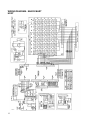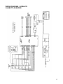
1
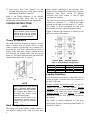
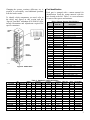
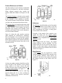
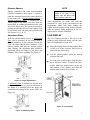
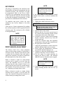
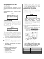
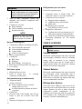
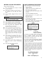
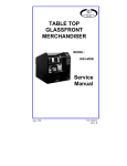
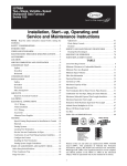
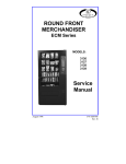
SATELLITE CAN/BOTTLE
VENDOR
BV 1
Covers Model:
3099
Service
Manual
A10067
January, 1999
P/N 4208379
Rev. D
TABLE OF CONTENTS
INTRODUCTION ................................................................................. 1
SPECIFICATIONS .............................................................................. 1
UNPACKING....................................................................................... 1
INSTALLATION .................................................................................. 2
LOADING INSTRUCTIONS ................................................................ 4
LIVE DISPLAY .................................................................................... 7
SET PRICES ....................................................................................... 8
DROP SENSOR ADJUSTMENT ........................................................ 8
REFRIGERATION SYSTEM ............................................................... 9
CARE & CLEANING ......................................................................... 10
BEFORE CALLING FOR SERVICE ................................................. 11
PARTS ORDERING PROCEDURE .................................................. 11
WIRING DIAGRAM - SNACK MART HOST ..................................... 12
WIRING DIAGRAM - SATELLITE CAN/BOTTLE VENDOR ............ 13
Record the Model Number and Serial Number of your machine below.
The Model and Serial numbers will be needed for you to obtain quick service and parts information for
your machine. The numbers are available on the identification plate located on the backside of the cabinet
of the vendor.
MODEL NUMBER: __________________________________________________
SERIAL NUMBER: __________________________________________________
ii
INTRODUCTION
This manual contains service and installation
guidelines, and instructions for the Model 3099
Satellite Can/Bottle Vendor.
The Satellite Can/Bottle Vendor is a refrigerated
can/bottle vendor with six (6) motor-driven vend
mechanisms capable of vending eight (8) different
selections or items. The vend compartments are
capable of vending containers of various sizes and
shapes including 20-ounce products.
The Satellite Can/Bottle Vendor must be connected
to a Snack Mart III or Snack Mart IIIA Glass Front
merchandiser or similar “host” machine. All
programming of the vend functions, pricing and
features are done at the host controller. Changes
and/or information can be retrieved without the
need of any additional accessories or remote parts.
When connected to the host vendor the electronics
within the host control system allows all selections
to be priced separately at various vend prices
ranging from $.05 to $99.95 in five cent increments.
Money must be inserted into the host vendor and
the selection made from the host to make a vend
from the satellite unit.
Electronic failures and service diagnostics are
recorded and “error code” messages will be
displayed to the service personnel when the
controller is placed in the Service Mode. Refer to
the host service manual for details.
SPECIFICATIONS
General
Height:
Width:
Depth:
Weight:
72 Inches
29 3/8 Inches
32 3/8 Inches, W/O Hopper
35 3/4 Inches, W/Hopper
652 Pounds
Electrical
Power:
Transformer:
Starting Amps:
Running Amps:
120 Volt AC, 60 Cycle, 15 Amp,
24 VAC, 75 VA
28 Amps
7.5 Amps
Capacity
Selections:
Total Capacity:
8 Select
144 Containers
Pricing
$0.05 to $99.95 (Controlled at host vendor)
Coinage
Shared with host vendor
Refrigeration
Type:
1/3 HP Hermetically Sealed High
Efficiency
Refrigerant: R134a
Charge:
7.25 Ounces
UNPACKING
This machine has been thoroughly inspected prior
to shipment and has been packaged in a manner to
prevent damage during transit.
The delivering carrier has accepted this vendor as
their responsibility. Any damage or irregularities
should be noted at the time of delivery and reported
to the carrier. Request a written inspection report
from the claims inspector to file any claim for
damage. File the claim with the CARRIER (NOT
THE MANUFACTURER) within 15 days after
receipt of the machine.
To unpack the vendor:
1. Cut and remove the straps that secure the
packaging material to the vendor.
2. Carefully remove all external packing material
from the vendor taking care not to mar or
damage the vendor’s finish.
3. Remove the protective plastic bag.
4. Inspect the machine for concealed shipping
damage. Report any damage hidden by the
packing material directly to the delivering
carrier.
5. Remove the “Knock-A-Way” Skid Boards by
placing a 2 X 4 under the vendor, inserting a
large screwdriver or prying tool into the groove
of the Knock-A-Way and splitting it in two.
1
Turn the leveling screws in as far as possible.
See Figure 1.
being “banked”. The vendor must be level to obtain
proper operation. When the vendor is level, the door
can be opened to any position and not move by
itself. Try the door half closed, straight out and in
the wide-open position before deciding the vendor
is level.
Grounding & Electrical
A10488
Figure 1. Removing the Skid Boards
6. Locate the key, taped inside the delivery
opening, and unlock the outer door. The Thandle latch will require several full turns
counter clockwise to open the main door.
7. Pull the power cord of the Satellite Vendor to its
full extension away from the back of the
cabinet. The cord will be approximately 6 ft.
(1.82 meters) long.
8. Remove all packing material, shipping brackets,
product kits, and tape from inside the vendor.
Adhesive residue can be removed with
denatured alcohol or common household
vinegar.
9. A model number, serial number and inspection
number appears on the final inspection form and
the serial plate of each vendor. Refer to these
numbers on all correspondence and inquiries
pertaining to this vendor.
INSTALLATION
Position the vendor in its place of operation to the
right of the host machine no further than 6 feet
(1.82 meters) from the power outlet or receptacle.
Check that the door will open fully without
interference. Leave at least 6 inches (15
centimeters) of space between the back of the
machine and any wall or obstruction for proper air
circulation and exhaust.
Level the vendor, making sure all levelers are
touching the floor. The rear leg levelers should be
adjusted first, especially when the equipment is
2
Prior to connecting the equipment, the integrity of
the main electrical supply must be checked for
correct polarity, presence of ground and correct
voltage. It is recommended that these checks be
repeated at 6-month intervals with the routine safety
electrical testing of the equipment itself.
To correct negative voltage, amperage, polarity, or
ground checks, consult a licensed electrician.
A noise suppressor has been installed in this
machine to compensate for any mains signal noise
that could interfere with the normal operation of the
controller.
For 120 Volt Vendors, the power source must be a
minimum 15 Amp, 120 Volt AC (±10%) 60 Cycle.
Voltage Check: When the AC voltmeter probes
are connected to the hot and neutral terminals,
the voltmeter should indicate 108 - 132 volts
AC.
Polarity and Ground Check: When the AC
voltmeter probes are connected to the hot and
ground terminals. the voltmeter should indicate
108 to 132 volts AC.
Amperage Check: At the fuse box or circuit
breaker panel, locate the proper circuit, and
ensure that the fuse or breaker protecting that
circuit is rated at 15 amps or greater.
NOTE
The hot side of the outlet should
always be counter-clockwise from
the ground. The neutral terminal
will be clockwise from the ground
terminal.
Shown in Figure 2 and 3 are two (2) properly
grounded and polarized wall outlets. Figure 2 is a
three-wire grounding type wall outlet. Figure 3 is a
two-wire outlet with a three-plug adapter in place.
4. Connect the umbilical cord from the Satellite
Vendor to the “H” (lower) connector of the host
machine. See Figure 5.
Verify that all harnessing and cables have been
properly routed to clear all moving parts and
will not interfere with the delivery of the
product.
A10489
Figure 2. Wire Outlet
A10492
Figure 5. H Connector on the Host
5. The Delivery Hopper is taped inside the bottom
area of the door. Remove and assemble as
shown in Figure 6. Secure with the four (4) bolts
and wing nuts provided.
A10490
Figure 3. Wire Outlet
Connecting to the Host
To connect the Satellite Vendor to the host
machine:
1. Remove power from both the host machine and
the Satellite Vendor.
2. Remove the hole plug from the back of the host
machine’s cabinet.
3. Insert the umbilical cord from the Satellite
Vendor through the hole in the back of the host
machine and secure the plate attached to the
umbilical cord. See Figure 4.
A10491
Figure 4. Umbilical Cord
A10493
Figure 6. Delivery Hopper Installation
6. Plug both the host machine and the Satellite
Vendor into the building power source.
7. Set vend prices for the Satellite Vendor. (Refer
to the “Set Prices” section.)
8. Load vending compartments and Live Display.
(Refer to the “Loading Instructions” section.)
9. Display items in the live display are visible to
the buying customer and agree with the products
loaded in the specific columns. (Refer to “Live
Display” section.)
10. Test vend both machines for proper operation.
11. Delivery Hopper is installed.
3
12. Vend prices have been properly set and
selection labels and price scrolls agree with the
programming in the host controller.
Refer to the Wiring Diagrams of the Satellite
Vendor and the host Snack Mart for proper
identification of the connections and components.
LOADING INSTRUCTIONS
NOTE
When loading the vendor verify
that the product in each selection
matches that in the live display
and that the price agrees with the
programming in the controller.
bottle modules consisting of two columns. Each
module can be configured to vend a single selection
alternately from either column or different
selections from each column. A total of eight
selections are available.
The bottle racks are factory-configured to use dual
columns for selections 1, 2, 3 and 4 and single
columns for the other four selections (5, 6, 7 and 8).
The vendor is factory-configured to vend most
major-brand 20 ounce-carbonated plastic bottles.
Figure 8 indicates the selections in relation to the
physical location of the motors.
Theory of Operation
The bottle racks are designed to support a vertical
stack of bottles with an ejector cam as a shelf.
When a product is vended the cam is rotated 110 ,
removing the shelf from underneath the stack of
bottles. At the same time a finger is rotated in to the
area between the bottom bottle and the second
bottle up. This finger holds the stack and allows the
bottom bottle only to fall. See Figure 7.
A10495
Figure 8. Motor – Selection Diagram
Table 1. Selection/Motor Configuration
MOTOR #
SELECTION
MOTOR #
SELECTION
1
2
3
H1
H2
H3
4
5
6
H4
H5 & H6
H7 & H8
Loading Guidelines
A10494
Figure 7. Ejector Cam and Finger
NOTE
When a selection is empty and a
vend is attempted, select other
item displays. The host controller
will configure that selection as
inoperative and prevent future
vends from being made.
Press the Service Button in the
host vendor to reset the “sold-out”
condition each time the machine
is filled.
Rack Configuration
The storage area of the Satellite Vendor consists of
two separate sliding racks. Each rack has three
4
Load the product from the top of the bottle rack as
shown in Figure 9 with the base of the container to
the back of the rack.
Product retainers and product guides are used to
confine the product in the column. Product
deflectors create a resting place for the mouth of the
container in the vend area of the column. Small
diameter spacers and back spacers are used to
position the container in the proper vend position in
the column.
The vendor is factory-configured to vend most
major-brand 20-ounce carbonated plastic bottles, as
described in Table 2.
Changing the spacers, retainers, deflectors, etc. is
required to successfully vend additional products
from the bottle vendor.
To identify which components you need, refer to
the tables and figures in this section and the
“Special Vend Kits” addendum (P/N 4209143). Kits
include illustrations and adjustments required for
specific containers.
A10496
Figure 9. Bottle Rack
Part Identification
Each part is stamped with a roman numeral for
identification. Read the roman numeral with the
hole located to the left. Table 3 is a cross-reference
for most of the spacers and retainers.
Table 3. Roman Numeral Part Numbers
Roman
No.
I
II
III
IV
V
VI
VII
VIII
IX
X
XI
XII
XIII
XIV
XV
XVI
XVII
XVIII
XIX
XX
XXI
XXII
XXIII
XXIV
XXV
XXVI
XXVII
XXVIII
XXIX
Part No.
4207178-001
4207226-001
4207226-003
4208219-001
4208222-001
4208222-003
4208223-001
4208310
4208316-001
4208316-002
4208320
4208332-001
4208348
4208349-001
4208349-003
4208381
4208383
4208936-001
4208935-001
4208934
4208936-003
4209141
4209142-003
4209142-001
4209574-001
4209574-003
4209575
4210368-003
4210368-001
Description
Retainer
2” Back Spacer – Right
2” Back Spacer – Left
Guide/Retainer – Tapered
1” Back Spacer – Right
1” Back Spacer – Left
Small Diameter Spacer
Deflector – Angled
3/8” Spacer – Left
3/8” Spacer – Right
Deflector – Flat
Guide
Retainer – Can
1” Back Spacer – Can –Right
1” Back Spacer – Can – Left
Deflector – Flat 12 oz. Can
Flexible Dia. Spacer
9/16” Back Spacer – Right
Very Small Diameter Spacer
Deflector – Wide Flat
9/16” Back Spacer – Left
Deflector – Angled 16 Oz. Can
¼” Back Spacer – Left
¼” Back Spacer – Right
1” Back Spacer – 250ml –Right
1” Back Spacer – 250ml –Left
Guide/Retainer – 250 ml
1.281” Back Spacer – Left
1.281” Back Spacer – Right
Table 2. Standard Loading Guidelines
CONTAINER
VOL
OZ.
MATERIAL
All Sport
20 Plastic
Coke
20 Plastic
Crystal Clear
16.9 Plastic
Dr. Pepper
20 Plastic
Evian
16.9 Plastic
Fruitopia
16 Glass
Generic Sodas 20 Plastic
Minute Maid
16 Glass
Mt. Dew
20 Plastic
Mystic
20 Glass
Nestea
16 Glass
Pepsi
20 Plastic
Power Ade
20 Plastic
Snapple
16 Glass
Sprite
20 Plastic
HEIGHT
(IN.)
DIA
PRODUCT
RETAINER
SLOT
8 1/2
9
8
8 7/8
8 1/2
6 7/8
8
6 7/8
8 9/16
7 1/2
6 7/8
8 9/16
7 1/2
6 7/8
9
2.87
2.85
2.56
2.89
2.60
2.88
2.91
2.88
2.85
2.96
2.88
2.85
2.93
2.88
2.85
I
I
I
I
I
I
I
I
I
I
I
I
I
I
I
B-4
B-4
A-4
B-4
A-4
B-3
B-4
B-3
B-4
B-3
B-3
B-4
B-4
B-3
B-4
PRODUCT
GUIDE
SLOT
XII
XII
XII
XII
XII
XII
XII
XII
XII
XII
XII
XII
XII
XII
XII
B-5
B-5
B-5
B-4
B-5
B-4
B-5
B-4
B-5
B-5
B-4
B-5
B-5
B-4
B-5
PRODUCT
DEFL.
VIII
VIII
VIII
VIII
VIII
XI
VIII
XI
VIII
XI
XI
VIII
VIII
XI
VIII
SMALL DIA
SPACER
BACK
SPACER
ADJUSTMENT
PLATE
IX/X
VII
4208382
VII
4208382
IX/X
4208382
5
Product Retainers and Guides
The side members in each column are adjustable
forward or backwards in one-inch increments.
When adjusted properly they confine the
product within the column. See Figures 10 and
11.
The Product Retainer is located on the outside
of the column and should be positioned as close
to the “shoulder” of the container as possible.
The Product Retainer should hold the container
yet allow some movement from front to back.
The Product Guide is located on the motor shaft
or inside of the column and should be positioned
one space forward. If the retainer can not be
positioned close enough to the shoulder of the
container, the Product Guide can be adjusted to
act as the Product Retainer.
Figure 10 shows the side member positions
when adjusted for different-size containers.
Place the shoulder rivets in the proper keyhole
slots and pull down to secure the side member.
When adjusted properly the container should be
free, with minimal movement from side to side
and front to back.
A10497
Figure 10. Product Retainers, Guides, and
Spacers
A10498
Figure 11. Product Retainers, Guides, and
Spacers
Deflectors
The Deflector should hold the neck of the bottle
and allow the bottom of the bottle to fall first
during a vend. It is mounted at the bottom of
each compartment and creates a resting place
for the mouth of the container.
Generally, if the mouth of the container rests
outside the bottle rack the angled product
deflector is used. If the mouth of the container
rests within the compartment the flat product
deflector is used.
When shipped from the factory, the angled
product deflector will be installed. The flat
product deflector will be located in the service
packet. 12 ounce cans require a special product
deflector which will be included in the kit when
ordered. See Figure 9.
Back Spacers
A Back Spacer may be required for a short
container so that the mouth of the container rests
on the product deflector. Back spacers are
mounted to the back of the column to position
the product forward in the bottle rack. See
Figure 12.
At least one product retainer should be used for
each selection. If the diameter of the product
being vended is too large, remove the side
member from the center or motor shaft side. Do
not remove both retainers. See Figure 11.
Special side retainers are used to vend long
tapered bottles and 12 oz. cans as shown in
Figure 11. Refer to the “Special Vend Kits”
addendum (P/N 4209143).
6
A10499
Figure 12. Back Spacer
Diameter Spacers
Narrow containers and some non-carbonated
(flexible) containers may require a spacer to
push the container towards the motor shaft area
of the bottle rack. A Small Diameter Spacer or
Flexible Diameter Spacer is mounted on the
outside panel of the bottle rack away from the
motor shaft, to confine the container in the vend
area of the bottle rack. The spacer is secured by
placing the Shoulder Rivets in the keyhole slots
on the bottle rack side and pulling downward.
See Figures 10, 11, & 13.
Adjustment Plates
With the small diameter spacer, an Adjustment
Plate can be mounted on the motor shaft to
prevent puncturing of the container. During the
vend, the finger should allow clearance of the
bottom product and stop the second product
from vending. The adjustment plate should be
positioned where the finger is just above the
diameter of the lower container. See Figure 13.
NOTE
Installation and/or
adjustments of the plate on the
motor shaft will affect both
columns in the bottle rack.
After adjustments are made, test vend the
selections to verify proper positioning of the
components. Make sure when loading the
vendor that the product being loaded coincides
with the product being displayed in the live
display and is properly identified.
LIVE DISPLAY
The Live Display provides a full view of the
products being dispensed along with the price
and selection number of each item.
Place the display item with the product label
in full view of the customer and secure in
place with the elastic strap.
Use the special product spacer for narrow
products and cans.
Set each price scroll to agree with the price
set at the host vendor. To access the price
scrolls, loosen the thumb screws at the top
and bottom of the display and slide the
display panel to the left. See Figure 15.
A10500
Figure 13. Finger Adjustments
A Stationary Plate is available for flexible noncarbonated containers to prevent movement of
the finger. It is installed below the finger and
underneath the spring on the motor shaft. See
Figure 14.
A10502
Figure 15. Live Display
A10501
Figure 14. Stationary Plate
7
NOTE
SET PRICES
All pricing is controlled by the controller in the
host machine and must be programmed into the
controller's memory. The vend prices can only
be programmed while in the Service Mode.
Vend prices are programmed into the memory
of the controller by using the selection keypad
to input the commands or requirements. A vend
price must be established for each selection.
To establish vend prices, follow the steps
outlined in the Service Manual of the host
machine.
Check prices of items programmed by pushing
the selection numbers on the keypad on the host
selection panel. The vend price will be flashed
in the digital display.
NOTE
When
establishing
vend
prices, make sure the price
scrolls and the selection
labels located in the live
display area agree with the
vend prices programmed into
the controller.
DROP SENSOR ADJUSTMENT
The delivery chute uses a drop (vibration)
sensor to detect when a product is vended after a
selection is made. The drop sensor detects when
a product hits the delivery chute and sends a
signal to the controller. The sensor is attached to
the underneath side of the delivery chute.
When a selection is made on a dual-column
selection and no signal is received from the
sensor, the controller will try to vend that
selection from the other column. If there is no
signal from the sensor after the second attempt,
the controller will put that selection in a “soldout” condition, preventing future vends.
When a selection is made on a single column
selection and no signal is received from the
sensor the controller will put that selection in a
sold-out status preventing future vends.
8
To reset the sold-out status in
the Satellite Vendor, the host
machine must enter and exit
the Service Mode.
If the drop sensor is not sensitive enough
multiple vends and/or a sold-out condition can
occur.
To adjust the sensitivity of the sensor:
1. Unplug the vendor at the power source.
WARNING
The power switch on the control board
mounting bracket shuts off the power to
the lights and control board only.
2. Open the door to the vendor.
3. Remove the two (2) screws on the front of
the control board mounting bracket located
in the bottom left corner of the cabinet.
4. Carefully work the control board mounting
bracket assembly forward away from the
refrigeration unit.
5. Locate the indicator light and adjustable
potentiometer at the top of the control board.
6. Re-apply power to the vendor.
7. Adjust the potentiometer counter-clockwise
until the indicator light comes on steady.
8. Slowly adjust the potentiometer clockwise
just until the indicator light goes out.
9. Continue to adjust the potentiometer in the
clockwise direction 3/4 of a revolution.
10. Test the sensor for proper operation by
tapping the delivery chute. The indicator
light will come on when the chute is tapped.
NOTE
Adjust
the
potentiometer
clockwise to make the sensor
more sensitive.
11. Unplug the vendor and re-install the control
board mounting bracket with the two (2)
screws.
REFRIGERATION SYSTEM
Cold Control
For the recommended temperature for soft
drinks of approximately 38 , set the cold control
to 2.
Minor adjustment may be necessary at higher
altitudes.
Unplug the power supply, remove screws
from thermostat. Use a jumper wire, or place
a screw through terminals; then restore
power and check if the unit runs.
Compressor trips on Overload
1. Improper voltage: 5-10% above, 5% below.
Using the voltage section of the MultiMeter, check the power source.
2. Overload defective:
NOTE
Setting the cold control to a
larger number will not cause
drinks to cool faster; it could
cause soft drinks to freeze.
Troubleshooting
Know and understand how to service the unit
and how it operates. Units may vary, but the
operation is basically the same. Never guess at
the problem, find the symptom before
attempting any repair.
NOTE
Most refrigeration problems
are electrical.
NOTE
Power must be off and fan
circuit open.
Using the resistance section of the MultiMeter, check terminals 1 and 3 for
continuity. If no continuity is measured
(infinity), overload may be tripped. Wait 10
minutes and try again. If still no continuity,
overload is defective.
3. Relay defective: Test with Multi-Meter. See
Figure 16.
Unscrew lead terminals and remove relay
from compressor. (Keep relay upright)
Check terminals 1 and S, or L and S.
Replace relay if there is continuity.
This system should not be worked on outside
the Factory Service Center. Three things that
can go wrong with a sealed system and should
be repaired at the Factory Service Center are:
Low Charge - usually caused by leaks; look
for oil around seals and welds. Unit will not
seal properly.
Restriction in Systems (unit frost, then
melts) - not cooling properly, low side in
vacuum
Bad valves - unit does not cool properly;
noisy compressor
Compressor will not start
Check to see if compressor has power:
1. Tripped breaker or blown fuse
2. Wall outlet faulty
3. Short or tear in power cord
4. Improper wiring
5. Faulty cold control
A10503
Figure 16. Schematic
4. Check compressor. See Figure 16.
Check winding resistance with the MultiMeter. If readings are not within 2 Ohms,
the compressor is faulty. Use RXI scale.
Table 4. Winding Resistance
APPROXIMATE RESISTANCE
READING ACROSS TERMINALS
COMMON to START:
COMMON to RUN:
RUN to START:
COMMON to SHELL:
12 Ohms
2 Ohms
14 Ohms
No Continuity
9
WARNING:
Wiring diagrams must be followed as
shown. Any deviation can cause serious
electrical hazard and potential damage or
rupture component electrical parts
5. Short in other component: Isolate and
eliminate each electrical component until
short is found.
6. Compressor is too hot
Dirty condenser
Faulty condenser motor or blade
Restricted air flow
NOTE
Condenser must be kept
clean of dirt and debris to
allow for proper air circulation
Noisy or vibrating unit
1. Components rubbing or touching each other
Check fan blades and motor
Loose shrouds and harness
Copper tubing
Loose or unsecured parts
2. Worn or aged grommets
3. Compressor
Bad Valves
Slugging
Bad windings. See Figure 16.
4. Relay frozen in start position. See Figure 16.
5. Low voltage
Unit short cycles
1. Differential set too close
2. Probe in wrong area – i.e., touching
evaporator or other metal.
Unit operates long or continuously
1. Thermostat faulty
2. Air flow restricted
Faulty evaporator motor or blades
causing coils to ice over
Air flow blocked by product in front of
evaporator
3. Gasket leak
4. Excessive load: After loading, unit will run
longer to pull out excessive heat from
product.
5. Shortage of refrigerant or restriction
10
Refrigerated space too warm
Restricted evaporator space
1. Evaporator motor or blades faulty. This
causes the coils to ice over the evaporator.
2. Condenser air flow restricted
Plugged or dirty condenser
Condenser motor or blades bad
Blade stuck
3. Condensing space restricted
Unit placed too close to a wall
4. Compressor - bad valves
Capillary tube will start frosting 8 to 10
inches past evaporator connection tube
Check for oil around brazed connections
5. Thermostat improperly set. The normal
setting is 2.
CARE & CLEANING
CAUTION:
Always
disconnect
BEFORE cleaning.
power
source
Cabinet Interior
Wash with a mild detergent and water, rinse and
dry thoroughly. Eliminate odors by including
baking soda or ammonia in the cleaning
solution. Plastic parts may be cleaned with a
quality plastic cleaner. Do not get the cleaning
solution on electrical components.
Cabinet Exterior
Wash with a mild detergent and water, rinse and
dry thoroughly. Clean occasionally with a
quality car wax. Remove and clean Condensate
Drain Hose to eliminate any deposits that may
restrict condensation water flow.
Refrigeration System
Clean dust from condenser and screen in the
front door with a soft bristle brush or a vacuum
cleaner. Remove any dirt or debris from the
refrigeration system compartment. If the
condenser coil is not kept clean, the compressor
will overheat or fail, voiding the sealed system
warranty. Clean the condensation pan.
BEFORE CALLING FOR SERVICE
Please check the following:
Does your machine have at least 6” of clear
air space behind it?
If the power is turned on at the fuse box, is
the machine the only thing that doesn’t
work?
Is the machine plugged directly into the
outlet?
WARNING:
Extension cords cause problems.
DO NOT USE EXTENSION CORDS.
Is the evaporator coil free of dust and dirt?
Is the condenser coil free of dust and dirt?
Is the compressor free of dust? (A blanket of
dust can prevent the compressor from
cooling off between workouts)
Is the circuit breaker at the fuse box reset?
Are evaporator fans running? Fold a sheet of
8 1/2” x 11” paper in half from top to
bottom so it is now 8 1/2” x 5 1/2”. Place the
paper in front of the evaporator coil and see
if the evaporator fans will blow the paper
away.
Is the condenser fan running? Fold a sheet of
8 1/2” x 11” paper in half. Place the paper in
front of the condenser coils and see if it
draws the paper to it.
Is the shelf in front of the evaporator coil
clear? (No tools or other air-restricting
items)
Is the cold control set as specified?
NOTE:
Setting
the
temperature
colder does not accelerate
cooling of product.
PARTS ORDERING PROCEDURE
When ordering parts, include the following:
1. Shipping address.
2. Address where the invoice should be sent.
3. The number of parts required.
4. The model number and serial number of the
machines.
5. Any special shipping instructions.
6. Carrier desired: air or air special, truck,
parcel post, or rail.
7. Signature and date.
8. If a purchase order number is used, be sure
that it is legible and visible.
9. Correct part number and description from
the pertinent part and/or parts manual.
NOTE
When “Right” and “Left” are
used with a part name, it is
taken to mean that the person
is facing the machine with the
door closed.
10. Mail your order to
VendNet™
P. O. Box 488
165 North 10th Street
Waukee, IA 50263-0488
All orders are carefully packed and inspected
prior to shipment. Damage incurred during
shipment should be reported at once and a claim
filed with the terminating carrier.
If you do not have the right parts manual,
contact the above address. They will provide a
copy for you, if available.
Do not wait until you receive the parts manual
to order; instead use the most accurate part
description you can. Include the model number
and serial number of the machine, the name of
the assembly in which the part is used, and if
practical, a sample part. Furnish any information
to enable our Parts Department to pinpoint the
exact part needed.
For additional information
Phone: 1-800-833-4411
Or
E-Mail: VendNet@Ecity.net
11
WIRING DIAGRAM - SNACK MART
HOST
A10504
12
WIRING DIAGRAM - SATELLITE
CAN/BOTTLE VENDOR
A10505
13