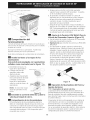
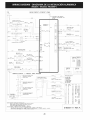
1
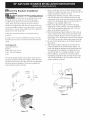
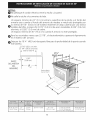
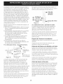
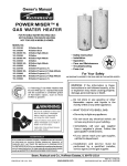
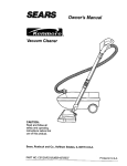
iNSTALLATiON AND SERVICE MUST BE PERFORMED BY A QUALiFiED iNSTALLER.
iMPORTANT: SAVE FOR LOCAL ELECTRICAL iNSPECTOR'S USE.
READ AND SAVE THESE iNSTRUCTiONS FOR FUTURE REFERENCE.
If the information in this manual is not followed exactly, a
fire or explosion may result causing property damage, personal injury
or death.
FOR YOUR SAFETY:
--•
•
•
•
--
Do not store or use gasoline or other flammable
in the vicinity of this or any other appliance.
WHAT TO DO IF YOU SMELL GAS:
vapors and liquids
Do not try to light any appliance.
Do not touch any electrical switch; do not use any phone in your
building.
Immediately call your gas supplier from a neighbor's phone. Follow
the gas supplier's instructions.
If you cannot reach your gas supplier, call the fire department.
Installation and service must be performed by a qualified installer,
service agency or the gas supplier.
Appliances
Installed
in the state
of Massachusetts:
This Appliance can only be installed
in the state of Massachusetts by a
Massachusetts licensed plumber or
gasfitter.
This appliance must be installed with a
three (3) foot / 36 in. long flexible gas
connector.
A"T" handle type manual gas valve
must be installed in the gas supply line
to this appliance.
IMPORTANT: Cabinet and
countertop width should match
the cutout width.
Locate Cabinet Doors
1" (2.5 cm) Min.
Cutout Opening.
" Min.
(61 cm Min.)
Grounded Junction Box or Wall Outlet Should Be Located 8" to 17" (20.3 cm
to 43.2 cm) From Right Cabinet and 2" to 4" (5.1 cm to 10.2 cm) From Floor.
Do not install the unit in the cabinet
35 7/8" (91.1cm) 36 5/8" (93cm)
31 5/16"
(79.5cm)
28 5/16" (71.9cm)
before
reading
next page.
30_+1/16" (76.2_+0.15cm)
21 3/4" (55.2cm) Min.
22 1/8" (56.2cm) Max
24" (61cm) Min. with
36 5/8" (93cm) Max.
35 7/8" (91.1cm)
backguard
NOTE: Wiring
diagram
Printed in United States
for
these
appliances
are enclosed
in this
booklet.
P/N 318201681
(0906) Rev. A
English - pages 1-11
Espahol - p_iginas 12-22
Wiring Diagrams - pages 23-24
NOTES:
_!
Do not pinch the power supply cord between the range and the wall.
Do not seal the range to the side cabinets.
24" (6! cm) minimum clearance between the cooktop and the bottom of the cabinet when
the bottom of wood or metal cabinet is protected by not less than 1/4" (0.64 cm) flame
Ot
retardant millboard covered with not less than No. 28 MSG sheet metal, 0.015"
stainless steel, 0.024" (0.6 mm) aluminum, or 0.020" (0.5 mm) copper.
30" (76.2 cm) minimum clearance when the cabinet is unprotected.
For cutouts below 22 7/8"(58.1
(0.4 mm)
cm), appliance will slightly show out of the cabinet.
Allow at least 19 ¼" (48.9 cm) clearance for door depth when it is open.
22 7/8" (58.1 cm) min.
23 1/4" (59.05 cm) max.
(see Note 4)
______
i
FRONT
OF
_F
CABINET
S
1 1/8"
(2.86 cm)
-_
Ref.
Door Open
(see note 5)
A
Side Panel
35 7/8" (91.1cm) 36 5/8" (93cm)
31 5/16"
(79.5cm)
28 5/16" (71.9cm)
30_+1/16" (76.2_+0.15cm)
21 3/4" (55.2cm) Min.
22 1/8" (56.2cm) Max
24" (61cm) Min. with
backguard
36 5/8" (93cm) Max.
35 7/8" (91.1cm)
withstand
important
Notes to the Installer
1. Read all instructions contained in these installation
instructions before installing range.
2. Remove all packing material from the oven
compartments before connecting the gas and
electrical supply to the range.
3. Observe all governing codes and ordinances.
4. Be sure to leave these instructions with the consumer.
5. Note: For operation at 2000 ft. elevations above see
level, appliance rating shall be reduced by 4 percent
for each additional 1000 ft.
heat at least 90°F above room
temperature
without shrinking, warping or
discoloring. Do not install the range over carpeting
unless you place an insulating pad or sheet of 1/4"
(10,16 cm) thick plywood between the range and
carpeting.
Make sure the wall coverings around the range
can withstand
the heat generated by the range.
Do not obstruct the flow of combustion air at the
oven vent nor around the base or beneath the
lower front panel of the range. Avoid touching the
vent openings or nearby surfaces as they may become
hot while the oven is in operation. This range requires
fresh air for proper burner combustion.
important
Note to the Consumer
Keep these instructions with your Use & Care Guide for
future reference.
Never leave children
alone or
unattended
in the area where an appliance is in
use. As children grow, teach them the proper, safe use
of all appliances. Never leave the oven door open when
the range is unattended.
IMPORTANT SAFETY
INSTRUCTIONS
Installation of this range must conform with local codes
or, in the absence of local codes, with the National Fuel
Gas Code ANSI Z223.1/NFPA .54-latest edition.
Stepping,
leaning
or sitting
on the
doors or drawers of this range can result in serious
injuries and can also cause damage to the range.
This range has been design certified by CSA
International. As with any appliance using gas and
generating heat, there are certain safety precautions you
should follow. You will find them in the Use and Care
Do not store items of interest to children in
the cabinets above the range. Children could be
seriously burned climbing on the range to reach items.
To eliminate the need to reach over the surface
burners, cabinet storage space above the burners
should be avoided.
Adjust surface burner flame size so it does not
extend beyond the edge of the cooking utensil.
Excessive flame is hazardous.
Do not use the oven as a storage space. This
creates a potentially hazardous situation.
Never use your range for warming or heating the
room. Prolonged use of the range without adequate
ventilation can be dangerous.
Do not store or use gasoline or other flammable
vapors and liquids near this or any other
appliance. Explosions or fires could result.
In the event of an electrical power outage, the surface
burners can be lit manually. To light a surface burner,
hold a lit match to the burner head and slowly turn
the Surface Control knob to LITE. Use caution when
lighting surface burners manually.
Reset all controls to the "off" position after using
a programmable
timing operation.
Guide, read it carefully.
• Be sure your range is installed and grounded
properly by a qualified installer or service
technician.
• This range must be electrically grounded in
accordance with local codes or, in their absence,
with the National Electrical Code ANSI/NFPA No.
70--latest edition. See Grounding Instructions.
Before installing the range in an area covered
with linoleum or any other synthetic floor
covering, make sure the floor covering can
@
All appliance can tip.
• Injury to persons could result.
• Install anti-tip bracket packed with
your appliance.
See installation Instructions.
To reduce the risk of tipping of the
range, the range must be secured by
properly installed anti-tip bracket(s)
provided with the range. To check if
the bracket(s) is installed properly,
grasp the top rear edge of the range and
carefully tilt it foward to make sure the range is
anchored.
FOR MODELS WITH SELF-CLEAN FEATURE:
Remove broiler pan, food and other utensils
before self-cleaning
the oven. Wipe up excess
spillage. Follow the predeaning instructions in the Use
and Care Guide.
Unlike the standard gas range, THIS COOKTOP
IS NOT REMOVABLE. Do not attempt to remove the
cooktop.
3
|
Cabinet
of water column pressure (3.5 kPa). The inlet pressure
to the regulator must be at least 1 " (.25 kPa) greater
than the regulator manifold pressure setting. Examples:
If regulator is set for natural gas 4" (10,16 cm) manifold
pressure, inlet pressure must be at least 5"(12.60 cm);
if regulator has been converted for LP/Propane gas
10"(25,4 cm) manifold pressure, inlet pressure must be
at least 11 "(27,9 cm).
Construction
_
To eliminate the risk of cabinet burns
and fire, do not have cabinet storage space above the
range. If there is cabinet storage space above range,
reduce risk by installing a range hood that projects
horizontally a minimum of 5" (12.7cm) beyond the
bottom of the cabinet.
Leak testing of the appliance shall be conducted
according to the instructions in step 4.
|
Countertop
Preparation
• The cooktop sides of the range fit over the cutout
edge of your countertop.
• If you have a square finish (flat) countertop, no
countertop preparation is required. Cooktop sides lay
directly on edge of countertop.
Formed front-edged countertops must have molded
edge shaved flat 3/4" (1.9 cm) from each front corner
of opening (Figure 1).
Tile countertops may need trim cut back 3/4"(1.9 cm)
from each front corner and/or rounded edge flattened
(Figure 1).
The gas supply line should be 1/2" or 3A" I.D. (Interior
Diameter)
|
Seal the openings
Seal any openings in the wall behind the range and
in the floor under the range after gas supply line is
installed.
Connect
supply
the range
to the gas
Important:
Remove all packing material and literature
from range before connecting gas and electrical supply.
To prevent leaks, put pipe joint sealant on all external
pipe threads.
Your regulator is in
location as shown.
(1.9 cm)
I
Formed
or tile countertop
trimmed
_A" (1.9 cm) back
front corners
of countertop
Figure I
Do not
at
allow regulator to
rotate on pipe when
tightening
fittings.
opening.
If the existing cutout width is greater than
30-1/16" (76,4 cm), reduce the 3A" (1.9 cm)
dimension.
• Countertop must be level. Place a level on the
countertop, first side to side, then front to back. If the
countertop is not level, the range will not be level.
The oven must be level for satisfactory baking results.
Cooktop sides of range fit over edges of countertop
opening.
|
Provide
an adequate
PressureRegulator Location
Figure 2
Connection
to Pressure
Regulator
The regulator is already installed on the appliance.
Do not make the connection too tight.
The regulator is die cast. Overtightening may crack the
regulator resulting in a gas leak and possible fire or
explosion.
Gas Supply
When shipped from the factory, this unit is designed
to operate on 4"(10,16 cm) water column (1.0 kPa)
Natural gas manifold pressure. A convertible pressure
regulator is connected to the range manifold and MUST
be connected in series with the gas supply line. If LP/
Propane conversion kit has been used, follow instructions
provided with the kit for converting the pressure
regulator to LP/Propane use.
Manual
Shutoff
Valve
Care must be taken during installation of range not to
obstruct the flow of combustion and ventilation air.
Off
Flare
Union
GAS FLOW
__
Connector
Flare
Union
Pressure
Regulator
Access
Cap
All connections must be wrench-tightened
Figure 3
For proper operation, the maximum inlet pressure to
the regulator should be no more than 14"(35,56 cm)
4
Assemble
the flexibleconnectorfromthe gassupplypipe
to the pressure
regulatorinthefollowingorder:
1. manualshutoffvalve(notincluded)
2. 1/2" nipple(notincluded)
3. 1/2"flareunionadapter(notincluded)
4. flexibleconnector(notincluded)
5. 1/2"flareunionadapter(notincluded)
6. 1/2" nipple(notincluded)
7. pressure
regulator(included)
Usepipe-jointcompound
madefor usewith Naturaland
LP/Propane
gasto sealallgasconnections.
If flexible
connectors
areused,becertainconnectors
arenot
kinked.
Thesupplylinemustbeequipped
with anapproved
manualshutoffvalve.Thisvalveshouldbelocatedin
thesameroomasthe rangeandshouldbein a location
thatallowseaseof openingandclosing.Donot block
access
to the shutoffvalve.Thevalveisfor turningon or
shuttingoff gasto the appliance.
t_
|
LP/Propane
Gas Conversion
This appliance can be used with Natural gas or LP/
Propane gas. It is shipped from the factory for use with
natural gas.
If you wish to convert your range for use with LP/
Propane gas, use the supplied fixed orifices located in a
bag containing the literature marked "FOR LP/PROPANE
GAS CONVERSION." Follow the instructions packaged
with the orifices for surface, oven and broil burners
conversion.
The conversion must be performed by a qualified service
technician in accordance with the manufacturer's
instructions and all local codes and requirements. Failure
to follow these instructions could result in serious injury
or property damage. The qualified agency performing
this work assumes responsibility for the conversion.
Failure to make the appropriate
conversion can result in serious personal injury and
property damage.
|
Electrical
Requirements
120 volt, 60 Hertz, properly grounded dedicated circuit
protected by a 15 amp circuit breaker or time delay fuse.
Note: Not recommended to be installed with a Ground
Fault Interrupt (GFI).
Do not use an extension
Shutoff Valve Open position
Grounding
Figure 4
Once regulator is in place, open the shutoff valve in the
gas supply line. Wait a few minutes for gas to move
through the gas line.
Check for leaks, After connecting the range to the gas
supply, check the system for leaks with a manometer. If
a manometer is not available, turn on the gas supply and
use a liquid leak detector (or soap and water) at all joints
and connections to check for leaks.
Do not use a flame to check for leaks
from gas connections. Checking for leaks with a flame
may result in a fire or explosion.
Tighten all connections as necessary to prevent gas
leakage in the range or supply line.
Disconnect this range and its individual manual
shutoff valve from the gas supply piping system during
any pressure testing of that system at test pressures
greater than 1/2 psig (3.5 kPa or 14" water column).
Isolate the range from the gas supply piping system
by closing its individual manual shutoff valve during any
pressure testing of the gas supply piping system at test
pressures equal to or less than 1/2 psig (3.5 kPa or 14"
water column).
cord with this range.
Instructions
IMPORTANT Please read carefully.
For personal
grounded,
safety, this appliance
must be properly
The power cord of this appliance is equipped with a
3-prong (grounding) plug which mates with a standard
3-prong grounding wall receptacle (see Figure 5) to
minimize the possibility of electric shock hazard from the
appliance.
The wall receptacle and circuit should be checked by
a qualified electrician to make sure the receptacle is
properly grounded.
Preferred Method
Grounding type
wall receptacl
Do not, under any
circumstances, cut,
remove, or bypass
the grounding
prong.
Power supply cord with
3-prong grounding plug.
Figure 5
Wherea standard2-prongwallreceptacle
is installed,
it isthe personal
responsibility
andobligationof the
consumer
to haveit replaced
bya properlygrounded
3-prongwallreceptacle.
Do not, underany circumstances,
cut or removethe
third (ground)prongfrom the power cord,
_:_[ Ir_j__
Install the anti-tip bracket at this
point before placing the range at its final
position. Follow the installation instructions on
page 11 or 12 or on the anti-tip bracket template
supplied with the range.
_To
provide an optimum installation, the top surface
of the countertop must be level and flat (lie on the
same plane) around the 3 sides that are adjacent
to range cooktop. Proper adjustments to make
the top flat should be made or gaps between the
countertop and the range cooktop may occur.
__
To reduce the risk of damaging your
appliance, do not handle or manipulate it by the
ceramic glass. Manipulate with care.
Disconnect
electrical
supplycordfrom
wallreceptacle
beforeservicing
cooktop.
|
Moving the Appliance
Servicing and Cleaning
for
Turn off the range line fuse or circuit breakers at the
main power source, and turn off the manual gas shut-off
valve. Make sure the range is cold. Remove the service
drawer (warmer drawer on some models) and open the
oven door. Lift the range at the front and slide it out
of the cut-out opening without creating undue strain
on the flexible gas conduit. Make sure not to pinch
the flexible gas conduit at the back of the range when
replacing the unit into the cut-out opening. Replace
the drawer, close the door and switch on the electrical
power and gas to the range.
Range Installation
Important
Note: Door removal is not a requirement for
installation of the range, but is an added convenience.
Refer to the Use
and Care Guide for
oven door removal
instructions,
Standard
Installation
Figure 6 cl-
_lnstall
base cabinets 30" (76.2 cm) apart. Make sure
they are plumb and level before attaching cooktop.
Shave raised countertop edge to clear 31 1/2" (81
cm) wide range top rim.
_lnstall
cabinet doors 31 " (78.7 cm) min. apart so it
will not interfere with range door opening.
For models
countertop exactly as shown on page 1.
equipped
with
Leveling
range in front of the cabinet opening.
_Make
sure that the cooktop glass which overhangs
the countertop clears the countertop. If necessary,
raise the unit by lowering the leveling legs.
_Slide
the range into the cutout opening and center
it before leveling it.
_Level
the range (see section 9). The floor where
the range is to be installed must be level. Follow
the instructions under "Leveling the Range- Models
Equipped with Leveling Device".
_,l_l="J
Adjust leveling legs so that the underside of the
cooktop is sitting on the countertop. Carefully
screw in (refer to Leveling the range: Models
equipped with Leveling Device") the back leveling
leg until the cooktop glass overhang touches slightly
the countertop. Then carefully screw in the front
two leveling legs until the cooktop glass overhang
touches slightly the countertop.
For models equipped
with
only (no leveling
device):
OThe
range cooktop overlaps the countertop at the
sides and the range rests on the floor. The cooktop
is 31 1/2" (81 cm) wide.
_Cutout
|Position
Device:
|Make
sure the front leveling legs and the rear
leveling device are setup higher than the height of
the cabinet.
Levelin Lg_L=eg
_Make
sure the four leveling legs (front and rear) are
setup higher than the height of the cabinet (shown
on page 3).
|_
Install the anti-tip
bracket
at
this point before placing the range at its final
position. Follow the installation instructions on
page 11 or 12 or on the anti-tip bracket template
supplied with the range.
_To
provide an optimum installation, the top surface
of the countertop must be level and flat (lie on the
same plane) around the 3 sides that are adjacent
to range cooktop. Proper adjustments to make
the top flat should be made or gaps between the
countertop and the range cooktop may occur.
_
|
_J__
To reduce the risk of damaging your
appliance, do not handle or manipulate it by the
ceramic glass. Manipulate with care.
_Position
range in front of the cabinet opening.
2.
_Make
sure that the glass which overhangs the
countertop clears the countertop. If necessary, raise
the unit by lowering the leveling legs.
_Eevel
the range (see section 9). The floor where
the range is to be installed must be level. Follow
the instructions under "Leveling the Range-Models
Equipped with Leveling Legs".
_Slide
Models
Equipped
with
3.
Needed
Installation
With Backguard
A backguard kit can be ordered through a Sears
Service Center. The cutout depth (213A" (5B,2cm) Min.,
221/s'' (56,2cm) Max.) needs to be increased to 24"
(61cm) when installing a backguard
Installation
With End Panel
An end panel kit can be ordered through a Sears
Service Center.
ust Rear Levelin¢
Installation
With Side Panel
A side panels kit can be ordered through a Sears
Service Center. Install cabinet doors 31 " (78,7cm) min.
apart so as not to interfere with range door opening.
Levelin
Leveling the Range
Models
Equipped
with
Leveling
Device
Font
Leveling
Leg
Level the range after installation in the cutout opening.
1. Open the range drawer. The leveling screws control
the height of the rear leg.
2. Adjust the appliance legs as follows until the
underside of the cooktop (or cooktop glass) surface
is sitting level on the countertop (Figure 7).
a.To adjust the front legs, use a wrench on the
leg base and turn counterclockwise to lower or
clockwise to raise the range.
b.To adjust the rear legs, use a ratchet or
a nutdriver and turn the leveling screws
counterclockwise to lower or clockwise to raise
3.
4.
5.
Legs
Place a level on the rack (see Figure 8). Take 2
readings with the level placed diagonally in one
direction and then the other. Level the range, if
necessary, by adjusting the 4 leg levelers with a
wrench (see Figure 17).
Taking care to not damage the countertop, slide
range into cutout opening and double check for
levelness.
the range into the cutout opening.
lf Accessories
Leveling
Level the range and set cooktop height before
installation in the cut-out opening.
1. Install an oven rack in the center of the oven.
Figure 7
the range.
Check if the range is level by installing an oven rack
in the center of the oven and placing a level on the
rack (Figure 8).
Take 2 readings with the level placed diagonally in
one direction and then the other. Level the range, if
necessary, by adjusting the leveling legs.
If the range cannot be level, contact a carpenter to
correct sagging or sloping floor.
Figure 8
7
Decorative
Rear Trim Installation
Main
(if required)
1.
2.
3.
4.
Disconnect the power from the range.
Make sure the range is leveled.
Pull range toward you.
Measure the distance between the floor and the
surface underneath the cooktop frame.
Mark that distance on the wall where the decorative
trim will be installed.
Draw a line.
Place the top of the decorative trim under that line.
Using the screws provided fix the decorative trim into
the wall.
Slide the range back into position as far as it will go
and reconnect the power source.
5.
6.
7.
8.
9.
Turn
between the
floor and
the
"'-..
"<_ame,
Figure 9
Gas Valve
position. You will hear the igniter sparking.
b. The surface burner should light when gas is available
to the top burner. Each burner should light within
four (4) seconds after air has been purged from supply
lines. Visually check that burner has lit.
c. Once the burner lights, the control knob should be
rotated out of the LITE position.
There are separate ignition devices for each burner. Try
each knob separately until all burner valves have been
checked.
Adjust
the
"LOW"
Setting
Check Operation
Refer to the Use and Care Guide packaged with the
range for operating instructions and for care and
cleaning of your range.
Remove all packaging from the oven before testing.
Install
This
range
as shown
Burner
Bases
is equipped
(see
Open
of
Surface
ignites.
b. Quickly turn knob to LOWEST POSITION.
c. If burner goes out, readjust valve as follows:
Reset control to OFF. Remove the surface burner
control knob, insert a thin-bladed screw driver into the
hollow valve stem and engage the slotted screw inside.
Flame size can be increased or decreased with the
turn of the screw. Adjust flame until you can quickly
turn knob from LITEto LOWEST POSITION without
extinguishing the flame. Flame should be as small as
possible without going out.
surface
underneath
the cooktop
\..
and
Burner
Valves
(see Figure 11)
a. Push in and turn each control to LITE until burner
"¸
zz_stance
J
Shutoff
Power
Check the Igniters
Operation of electric igniters should be checked after
range and supply line connectors have been carefully
checked for leaks, and range has been connected to
electric power. To check for proper lighting:
a. Push in and turn a surface burner knob to the LITE
|
ii
on Electrical
Figure
and
with
Burner
Caps
sealed
burners
10).
a. Unpack burner bases and
burner caps.
b. Place burner bases over
each gas opening.
c. Make sure the burner
is properly aligned and
leveled. Place burner caps
over appropriate burner
bases.
NOTE: There are no burner
adjustments necessary on this
range.
Figure 11
i
i
Figure 10
|
front of oven bottom from oven front frame, and pull the
oven bottom out of the oven. Remove burner baffle so that
burner flame can be observed.
Operation of Oven Burners and Oven
Adjustments
11.5.1 Electric Ignition Burners
Operation of electric igniters should be checked after
range and supply line connectors have been carefully
checked for leaks, and range has been connected to
electric power.
If the flame is yellow, increase air shutter opening size (see
"2" in Figure 13). If the entire flame is blue, reduce the air
shutter opening size.
To adjust frame loosen lock screw (see "3" in Figure 13),
reposition air shutter, and tighten lock screw. Replace oven
bottom.
Burner Tube
The oven burner is equipped with an electric control system
as well as an electric oven burner igniter. If your model is
equipped with a waist-high broil burner igniter, it will also
have an electric burner igniter. These control systems require
no adjustment. When the oven is set to operate, current
will flow to the igniter. It will "glow" similar to a light bulb.
When the igniter has reached a temperature sufficient to
ignite gas, the electrically controlled oven valve will open
and flame will appear at the oven burner. There is a time
lapse from 30 to 60 seconds after thermostat is turned ON
before the flame appears at the oven burner. When the oven
reaches the display setting, the glowing igniter will go off.
The burner flame will go "out" in 20 to 30 seconds after
igniter goes "OFF". To maintain any given oven temperature,
this cycle will continue as long as the display is set to operate.
After removing all packing materials and literature from
the oven:
a) Set the oven to BAKE at 300% See Use & Care Guide
for operating instructions.
b) Within 60 seconds the oven burner should ignite.
Check for proper flame, and allow the burner to cycle
once. Reset controls to off.
c) If your model is equipped with a high-waist broiler,
set oven to broil. See Use & Care Guide for operating
instructions.
d) Within 60 seconds the broil burner should ignite. Check
for proper flame. Reset controls to off.
11.5.2 Air Shutter-Oven
L wer
Oven Baffle
(
Figure 12
Lock Screw
Air
Shutter _
11.5.3 Air Shutter-Broil
)Orifice Hood
Figure 13
Burner
The approximate flame length of the burner is 1 inch
(distinct inner cone of blue flame). To determine if the broil
burner flame is proper, set the oven to broil. If flame is
yellow, increase air shutter opening size (see "2" in Figure
13 ). If the entire flame is blue, reduce the air shutter
opening size. To adjust, loosen lock screw (see "3" in
Figure 13), reposition air shutter, and tighten lock screw.
When All Hookups
are Complete
Make sure all controls are left in the OFF position.
Make sure the flow of combustion and ventilation air to
the range is unobstructed.
Model
and Serial Number
Location
The serial plate is located on the oven front frame behind
the oven door (some models) or on the drawer side
frame (some models).
Burner
When ordering parts for or making inquiries about your
range, always be sure to include the model and serial
numbers and a lot number or letter from the serial plate
on your range.
Waist-High
Shutter Burler
/
Your serial plate also tells you the rating of the burners,
the type of fuel and the pressure the range was adjusted
for when it left the factory.
Lower Oven Bottom
_=-Air Shutter
(removable)
Before
The approximate oven burner flame length is 1 inch
(distinct inner cone of blue flame).
You Call for Service
Read the Before You Call Checklist and operating
instructions in your Use and Care Guide. It may save you
time and expense. The list includes common occurrences
that are not the result of defective workmanship or
materials in this appliance.
To determine if the oven burner flame is proper, remove the
oven bottom and burner baffle and set the oven to bake at
300%
To remove the oven bottom, remove oven hold down
screws at rear of oven bottom. Pull up at rear, disengage
Refer to your Use & Care Guide for Sears service phone
numbers or call 1-800-4-MY-HOME®.
9
|
Anti-Tip
Brackets
1. Draw a center line (CL) on the floor where the range
should be installed. Also draw a line on the floor at the
Installation
instructions
|
Models
Equipped
with
Leveling
range back position if there is no wall.
2. Unfold paper template and place it flat on the floor
with the right rear corner positioned exactly on the
intersection of the center and back lines you just drew
before. (Use the diagram below to locate brackets if
template is not available (Figure 14)).
3. Mark on the floor the location of the 4 mounting
holes shown on the template. For easier installation,
3/16"(0,48 cm) diameter pilot holes 1/2"(1,27 cm)
deep can be drilled into the floor.
4. Remove template and place bracket on floor. Line up
holes in bracket with marks on floor and attach with
Device
To reduce the risk of tipping of the range,
the range must be secured to the floor by properly
installed anti-tip bracket and screws packed with the
range. These parts are located in the oven. Failure to
install the anti-tip bracket will allow the range to tip over
if excessive weight is placed on an open door or if a child
climbs upon it. Serious injury might result from spilled hot
liquids or from the range itself.
Follow the instructions below to install the anti-tip
brackets.
4 screws provided. Bracket must be secured to solid
floor (Figure 15). If attaching to concrete floor, first drill
3/16"(0,48 cm) dia. pilot holes using masonry drill bit.
5. Be sure the 4 leveling legs are at the highest position
they can be.
6. Slide range into place making sure structure of the
range is trapped by the anti-tip bracket (Figure 14).
Lower the range by adjusting the 4 leveling legs until
the underside of the cooktop is sitting level on the
countertop. Refer to "Leveling the Range" section.
7. After installation, verify that the anti-tip bracket is
engaged by grasping the top rear edge of the range
and carefully attempt to tilt it forward to make sure
range is properly anchored.
If range is ever moved to a different location, the antitip brackets must also be moved and installed with the
range.
Tools Required:
Adjustable Wrench
Ratchet
Drill & 1/8"(0,32 cm) bit
5/16" (0,8 cm) Nutdriver
Level
The anti-tip bracket attaches to the floor at the back of
the range to prevent range from tipping. When fastening
bracket to the floor, be sure that screws do not penetrate
electrical wiring or plumbing. The screws provided will
work in either wood or concrete.
i}
i}
i}
i}
i}
Floor
Mount_
Screws
Figure 15
BACK
Figure 14
10
|
1.
Models Equipped with Levelin
To reduce the risk of tipping of the range,
the range must be secured to the floor by properly
installed anti-tip brackets and screws packed with the
range. These parts are located in a plastic bag in the
oven. Failure to install the anti-tip brackets will allow the
range to tip over if excessive weight is placed on an open
door or if a child climbs upon it. Serious injury might
result from spilled hot liquids or from the range itself.
2.
3.
Follow the instructions below to install the anti-tip
brackets.
If range is ever moved to a different location, the antitip brackets must also be moved and installed with the
range. To check for proper installation, see step 5.
4.
Tools Required:
5/16" (0,79 cm) Nutdriver or Flat Head Screwdriver
Adjustable Wrench
Electric Drill
5.
3/1 6"(0,5 cm) Diameter Drill Bit
3/1 6"(0,5 cm) Diameter Masonry Drill Bit (if installing in
concrete)
Brackets attach to the floor at the back of the range to
hold both rear leg levelers. When fastening to the floor,
be sure that screws do not penetrate electrical wiring or
plumbing. The screws provided will work in either wood
or concrete.
Unfold paper template and place it flat on the floor
with the back and side edges positioned exactly
where the back and sides of range will be located
when installed. (Use the diagram below to locate
brackets if template is not available. (Figure 16))
Mark on the floor the location of the 4 mounting
holes shown on the template. For easier installation,
3/16" (0.5 cm) diameter pilot holes 1/2" (1.3 cm)
deep can be drilled into the floor.
Remove template and place brackets on floor
with turned up flange to the front. Line up holes
in brackets with marks on floor and attach with 4
screws provided. Brackets must be secured to solid
floor. If attaching to concrete floor, first drill 3/16"
(0.5 cm) dia. pilot holes using a masonry drill bit.
Level range if necessary, by adjusting 4 leg levelers
with wrench (Figure 17). A minimum clearance of
1/8" (0.8 cm) is required between the bottom of the
range and the rear leg levelers to allow room for the
anti-tip brackets.
Slide range into place making sure rear legs are
trapped by ends of brackets. Range may need to
be shifted slightly to one side as it is being pushed
back to allow rear legs to slide under brackets. You
may also grasp the top rear edge of the range and
carefully attempt to tilt it forward to make sure
range is properly anchored.
i Anti-tip Bracket
Back Edgeof Range
or RearWall
_ -
CL.,-"
=
.9
<'4_'
1/8" _.
(23.2 cm) "
/"..
Anti-tip Bracket
18'4 '''_"
.(46.4 cm)
/.._r" -
28 1/8"
'-,
_,j(71.4 cm)
(Rearwidth of range
with body sides)
(eL = Center line
Figure 17
Slide Back
Figure 16
11
LA INSTALACION Y EL SERVICIO DEBEN SER EFECTUADOS POR UN INSTALADOR CALIFICADO
IMPORTANTE: GUARDE ESTAS INSTRUCCIONES PARA USO DEL iNSPECTOR LOCAL DE
,//7"
__
ELECTRiCiDAD. LEA Y GUARDE ESTAS 'NSTRUCC'ONES
PARA...
REFERENC'A FUTURA.
A -':'\, "\,
(,
)
IF_
Si Jainformaci6n contenida en este manual no es seguida
exactamente, puede ocurrir un incendio o expJosi6n causando daEos
materiaJes, Jesionpersonal o Jamuerte.
"L._
PARASU SEGURIDAD:
-- No aJmaceneni utiJice gasoJina u otros vapores y JiquidosinflamabJesen Ja
proximidad de _ste o de cuaJquier otro artefacto.
-- QUE DEBEHACERSJPERCIBE
OLORA GAS:
• No trate de encender ningun artefacto.
• No toque ningun interruptor eJ_ctrico; no use ningun teJ_fono en su edificio.
• LJamea su proveedor de gas desde eJteJ_fono de un vedno. Siga Jas
instruccionesdel proveedor de gas.
• Si no Jogracomunicarsecon su proveedor de gas, JJameaJdepartamento de
bomberos.
-- La instaJaciony el servido de mantenimiento deben ser efectuados por un
instaJadorcaJificado, Jaagenda de servido o el proveedor de gas.
Aparatos
InstaJados en el estado
de Massachusetts;
Este Aparato sOlo puede set instalado
en el estado de Massachusetts por un
plomero o ajustador de gas licenciado
de Massachusett.
Este aparato se debe instalar con un
largo conector flexible de gas de tres (3)
pies/36 pulgadas.
Una wqlvulamanual de gas de tipo manija
de forma de "T" sedebe instalar en la
linea del suministro de gas de este aparato.
E
30" Min.
J_(76.2
La superfide debe
estar plana y niveJada
IMPORTANTE: El ancho de la
cubierta y el armario debe de set
igual al ancho deJ corte.
M[n. 5 '
1 1/2"M_ix
_"
•
(3.8 cm M_ix.)
Acepille el borde _
subido a que
/
J
X II
dejeespacio
_
para,un borde
_ IJ_/A
31 Y2 (81 cm) de _
7_
anchura de estufa
_
I
\
(
(12.7cm)de la pared
ambos lados...
._,_
- ..---I--_
_-1¢
_
__
L
_
1/2"
,'_
)
J
(81
ExactoI
I
(33 cm)
(45.7cm)Min.
I
- __
/
,_._
.
18" Min.
_
1/_ _1 I
Localice las puertas del
---"L.
30" Mrn.
_
J:_--31
I
I
(area sombreada)m_x_
,..,....
cm Min.)
'_1
I _
_/4" rain.
_l(2"_nirl.
L_.___
_"_--,
_
Approx.17/8"
_-'L::_
.....
(4.8 cm)
:
........
::j
![
armario 1 (2.5 cm)min
del hueco de la abertura. _
JC]
#>""
/
__tf
r_/_...-.......
-/
.............
_
/
/
",./
La caja de empalmes o el enchufe con puesta a tierr'a deberia situarse de 8" a 17" (20.3
cm a 43.2 cm) del armario derecho y de 2" a 4" (5.1 cm a 10.2 cm) del suelo.
No instale la unidad en el gabinete si no ha leido esta p_qgina.
35 7/8" (91.1cm) 36 5/8" (93cm)
30"
(76.2cm)
31 5/16"
(79.5cm)
28 5/16" (71.9cm)
30 _+ 1/16"
(76.2 _+0.15 cm)
21 3/4" (55.2cm) Min.
22 1/8" (56.2cm) Max
36 5/8" (93cm) Max.
35 7/8" (91 .lcm)
24" (61cm) Min. with backguard
NOTA: Se adjunta
el diagrama
Impreso en los Estados Unidos
de cables
de esta
cocina
al final
de este
libreta.
P/N 318201681
(0906) Rev. A
English - pages 1-11
Espahol - p_qginas 12-22
Diagrama de la instalaci6n alambica - p_iginas 23-24
NOTAS:
No pellizque el cordon electrico entre la estufa y la pared.
_) No selle la estufa a los armados de lado.
Un espacio minimo de 24" (61 cm) entre la superficie de la estufa y el fondo del
armario esto cuando el fondo del armado de madera o metal est,1 protegido pot
no menos de 1/4" (0.64 cm) de madera resistente al fuego cubierta pot una I_imina
_) met_ilica de MSG, n0mero 28, 0.015" (0.4 mm) de acero inoxidable, 0.024" (0.6 mm)
aluminio, 6 0.020" (0.5 ram) de cobre.
Un espado minimo de 30" (76.2 cm) cuando el armado no este protegido.
_lb Para los recortados menos que 22 7/8", el electrodomestico
en el exterior del armado.
apareceria ligeramente
Deje pot los 19 ¼" (48.9 cm) de espado libre para la profundidad
este abierta.
de la puerta cuando
22 7/8" (58.1 cm) min.
23 1/4" (59.05 cm) max.
÷
(yea la nota 4) ÷
r"
r
m
PARTE
DELANTERA
DEL
ARMARIO
1 1/8"
_(2.86
cm)
Ref.
Puerta abierta
(vea la nota 5)
A
lateral
35 7/8" (91.1cm) 36 5/8" (93cm)
30"
(76.2cm)
31 5/16"
(79.5cm)
28 5/16" (71.9cm)
30 _+ 1/16"
(76.2 _+0.15 cm)
21 3/4" (55.2cm) Min.
22 1/8" (56.2cm) Max
24" (61cm) Min. with backguard
13
36 5/8" (93cm) Max.
35 7/8" (91 .lcm)
Notas
importantes
para
Lea todas las instrucciones contenidas en este manual antes
de instalar la estufa.
2.
Saque todo el material usado en el embalaje del
compartimiento del homo antes de conectar el suministro
electrico o de gas a la estufa.
Observe todos los cOdigos y reglamentos pertinentes.
Deje estas instrucciones con el comprador.
Nota: Para la utilizaciOn a m_s de 2 000 pies de altura, la
potencia del aparato deber_ ser reducida de 4 por ciento a
cada 1 000 pies adicionales.
3.
4.
5.
Nota
Importante
menos que coloque una plancha de material aislante de por
Io menos 1/4 pulgada, entre la estufa y la alfombra.
, Asegurese de que el material que recubre las paredes
alrededor de la estufa, pueda resistir el calor generado
por la estufa.
, No obstruya el flujo del aire de combustion
en la
ventilaci6n
del homo ni tampoco alrededor de la base
o debajo del panel inferior delantero de la estufa. Evite
tocar las aberturas o _ireas cercanas de la ventilaciOn, ya
que pueden estar muy calientes durante el funcionamiento
del homo. La estufa requiere aire fresco para la combusti6n
apropiada de los quemadores.
el Instalador
1.
para el Consumidor
Conserve estas instrucciones y el Manual del Usuario para
referencia futura.
en un area donde
Nunca deje ni_os solos o desatendldos
un artefacto esta siendo usado. A
medida que los niflos crecen, ensefleles el uso apropiado y de
seguridad para todos los artefactos. Nunca deje la puerta del
homo abierta cuando la estufa est,1desatendida.
IMPORTANTES
INSTRUCCIONES DE
SEGURIDAD
No se pare, apoye o siente en las
puertas o cajones de esta estufa pues puede resultar en
serias lesiones y puede tambien causar daEo a la estufa.
o No almacene articulos que puedan interesar a los
niBos en los gabinetes sobre la estufa. Los niflos pueden
quemarse seriamente tratando de trepar a la estufa para
alcanzar estos articulos.
Instalaci6n de esta estufa debe cumplir con todos los c6digos
locales, o en ausencia de c6digos locales con el C6digo
Nacional de Gas Combustible ANSI Z223.1/NFPA .54--01tima
edici6n.
, Los gabinetes de almacenamiento
sobre la estufa
deben set evitados, para eliminar la necesidad de tenet
que pasar sobre los quemadores superiores de la estufa
para Ilegar a ellos.
Ajuste el tama_o de la llama de los quemadores
superiores de tal manera que esta no sobrepase el
borde de los utensilios de cocinar. La llama excesiva es
peligrosa.
, No use el horno como espacio de almacenaje. Esto
crear_i una situaciOn potencialmente peligrosa.
Nunca use la estufa para calentar el cuarto. El uso
prolongado de la estufa sin la adecuada ventilaciOn puede
resultar peligroso.
o No almacene ni utilice gasolina u otros vapores y
liquidos inflamables en la proximidad de este o de
cualquier otto artefacto electrico. Puede provocar
incendio o explosi6n.
En caso de una interrupti6n del servicio electrico, es posible
de encender los quemadores de superficie a mano. Para
encender un quemador de superficie, acerque un f6sforo
encendido del cabezal del quemador, y gire delicadamente
el bot6n de control de superficie a LITE(encendido). Tener
cuidado al encender los quemadores a mano.
Ajuste todos los controles a la posici6n "OFF" (apagada)
despues de haber hecho una operacion con tiempo
programado.
El diseflo de esta estufa ha sido certificado por la CSA
Internacional. En _ste como en cualquier otro artefacto que use
gas y genere calor, hay ciertas precauciones de seguridad que
usted debe seguir. Estas ser_in encontradas en el Manual del
Usuario, I_alo cuidadosamente.
, Asegurese de que la estufa sea instalada y conectada a
tierra en forma apropiada por un instalador calificado o
pot un tecnico.
, Esta estufa debe set electricamente
puesta a tierra de
acuerdo con los c6digos locales, o en su ausencia, con
el C6digo Electrico Nacional ANSI/NFPA No. 70, ultima
edici6n. Yea las instrucciones para la puesta a tierra en la
p_igina 4.
o Antes de instalar la estufa en un area cuyo piso
este recubierto con lin6leo u otro tipo de piso
sintetico, asegurese de que estos puedan resistir una
temperatura
de pot Io menos 90°F sobre la temperatura
ambiental sin provocar encogimiento,
deformaci6n
o
decoloraci6n.
No instale la estufa sobre una alfombra al
• Todas las estufas pueden volcarse.
• Esto podria resultar en lesiones
personales.
• Instale el dispositivo anti vuelcos que se
ha empacado junto con esta estufa.
PARA MODELOS AUTOLIMPIANTES:
Saque la asadera, alimentos o cualquier otto utensilio
antes de usar el cido de autolimpieza
del homo. Limpie
todo exceso de derrame de alimentos. Siga las instrucciones
de prelimpiado en el Manual del Usuario.
• A diferencia de la gama estandar cocinas de gas, ESTA
PLANCHA DE COCINA NO ES MOVIBLE. No intente quitar
la plancha de cocina.
vuelque la estufa, hay que asegurarla
adecuadamente
colo candole los soportes
Para reducirque
el riesgo
de que se Para
antivuelco
se proporcionan.
comprobar si estos estan instalados y
apretados en su lugar como se debe, ase el borde
trasero superior de la estufa y cuidado samente incline
la hacia adelante para asegurar que la estufa se ancle.
14
roll Construcci6n
Para la operaci6n apropriada, la m_ixima presi6n de
entrada al regulador no debe execeder la presi6n de una
columna de agua de 14"(35,56 cm) (3.5 kPa). La presi6n
de entrada al regulador debe set por Io menos 1" (.25
kPa) m_is grande que la wilvula distribuidora.Ejemplos:
Si regulador se pone para el gas natural con una presi6n
de 4"(10,16 cm), la presi6n de entrada al regulador debe
set por Io menos 5"(12.60 cm); si el regulador se ha
convertido para gas LP/Propane 10"(25,4 cm)la presi6n
de entrada al regulador debe set pot Io menos 11"(27,9
del armario
F_
Para eliminar el riesgo de
quemaduras o de fuego tratando de alcanzar algo pot
encima de las zonas calientes, evite de colocar articulos
sobre la cocina. Si cree necesitar este espacio, el riesgo
puede disminuir si instala un sombrerete que proteja
horizontalmente un minimo de 5" (12.7cm) sobre la
base del armario.
|
Preparacion
del mostrador
• Las extremidades de la cocina sobrepasan el horde de
su mostrador.
Si tiene un mostrador
con las extremidades
cuadradas
(planas),
no se necesita
ninguna
preparaci6n del mostrador.
El reborde de frente de mostradores moldeados
deben tenet hordes moldeados a 3/4" (1 .gcm) a partir
de cada extremidad de la apertura (Figura 2).
Los mostradores enazulejos deber_in necesitar un
recorte de 3/4" (1.9 cm) a partir de cada extremidad
y/o un horde redondeado aplanado (Figura 2).
cm).
Un examen de detection de fugas del aparato debe set
realizado segOn las instrucciones en el paso 4.
La linea de fuente de gas debe set de 1/2" o de 3A".
|
Selle
las aperturas
sella todas las aperturas en la pared detr_is de la estufa y
en el suelo debajo de la estufa despu@sque la linea del
suministro de gas sea instalada.
Conecte la estufa al suministro de gas
Importante:
Quite todo el material de embalaje y
literatura de la estufa antes de conectar el gas y la fuente
el@ctrica.
31_/,,_
(81 cm)
recortado
/
Para evitar fugas, aplique
sellador de tuberias en
_
en las esquinas
(1.9 cm)
I
• Si el ancho
abertura
Figura 1
de la abertura
todas las partes roscadas
machos (exterior) de la
tuberia. El regulador se
encuentra en el lugar
que se muestra en la
ilustraci6n. (Figura 4)
moldeado o enazulejo
3/4" (1.9 cm) hada atr&s
del
de frente
de la
del mostrador.
mostrador
es
mas grande que 30 1/16" (76,4 cm), ajuste a las
dimensiones como para el 3/4" (1.9).
El mostrador
deber ser nivelado.
Coloque un
nivelador sobre el mostrador, primero de lado a lado
y luego del frente hacia atr_is. Si el mostrador no est,1
nivelado, la cocina no estate1 nivelada. El homo debe
ser nivelado para tenet resultados satisfactorios
al
hornear. Las extremidades de la plancha de la cocinar
sobrepasan los hordes de la abertura del mostrador.
Proporcione
adecuado
un suministro
F .__
No
permita que el
regulador gire sobre la
tuberia al apretar las
uniones.
UbicaciOn del
regu _dor de presiOn
Figura 2
Conecte
el Regulador
de Presion
El regulador de presi0n esta ya instalada para la estufa.
No haga la conexi6n demasiado
apretada. El regulador es de die cast. El apretar
demasiado puede agrietar el regulador dando pot
resultado una fuga de gas y un fuego o una explosi6n.
Valvula de
FLUJO DEL GAS
Regulador
_
cierre
Uni6n
Uni6n de presi6n
manual
,_
de gas
Cu_indo se envia de la f_ibrica, esta unidad ha sido
ajustada para operar con un mOltiple de admisi6n para
gas natural de 4" (10.16 cm)(1.0 kPa). Un regulador
de presi6n convertible esta conectado a la wilvula
distribuidora y DEBEset conectado con la tuberia del
suministro de gas. Si el juego de conversi6n del propano
LP/Propano se ha utilizado, sigue las instrucciones
proporcionadas el juego para convertir el regulador de
presi6n al uso de LP/Propano.
(On) _
Boquilla
Apagado
(Off)
se debe de tenet cuidado durante la instalaci6n de la
Conector
flexible
Boquill_
Tapa de
entrada
Todas las conexiones deben set apretadas con
una Ilave inglesa- Figura 3
estufa para no obstruir el flujo de aire de combusti6n y
ventilaci6n
15
Re0nael conectorflexibledeltubodelsuministro
degas
al regulador
de lapresiOn
en laordensiguiente:
1. V_ilvula
decierremanual(noincluido)
2. Boquillade 1/2"(noincluido)
3. 1/2"Adaptadordeunion (noincluido)
4. Conectorflexible(noincluido)
5. 1/2"Adaptadordeunion (noincluido)
6. Boquillade 1/2" (noincluido)
7. reguladordepresiOn(incluido)
Useselladorparaunionesdetuberiashechoparael
usodegasnaturaly LP/Propane
parasellartodaslas
conectiones
degas.Siseutilizanlosconectadores
flexibles,asegures_
dequelosconectadores
noest_in
enroscados.
Lalineadelsuministro
sedebedesetequipadadeuna
wilvuladecierremanualaprobada.
Estawilvulasedebe
Iocalizarenel mismocuartoquelaestufay debeestaren
unaIocalizaci6n
quepermitalafacilidaddelaaberturay
delcierre.Nobloqueeelacceso
a la wilvula.Lawilvulaes
paraencender
o apagarelgasdelaparato.
Aisle la estufa del sistema de tuberia
del suministro
de gas cerrando su wilvula de cierre manual durante
cualquier prueba de presiOn del sistema de tuberia del
suministro de gas prueba de presiOn iguala a o a menos
de 1/2 psig (3,5 kPa o 14" columna de agua).
|
Conversion
para uso de Propano
Liquido
Este aparato puede set usado con gas natural o propano
liquido. Ha sido ajustado en la f_ibrica para operar con
gas natural solamente.
Si desea convertir su estufa para uso con propano
liquido, use los orificios provistos ubicados en el bolso
que contiene la literatura titulada "FOR LP/PROPANEGAS
CONVERSION." Siga las instrucciones que vienen con los
orificios.
La conversion debe set efectuado pot un t_cnico de
servicio capacitado, de acuerdo con las instrucciones
del fabricante y con todos los cOdigos y requisitos
de las autoridades correspondiente. El no seguir las
instrucciones podria dar como resultado lesiones graves
o da_os a la propiedad. El organismo autorizado para
Ilevar a cabo este trabajo asume la responsabilidad de la
conversion.
La falta de una conversion apropiada
puede resultar en lesiones graves y dahos a la propiedad.
Valvula de cierre
|
=
Requisitos
electricos
120 voltio, 60 Hertzio, circuito dedicado apropiadamente
puestos a tierra protegido pot un circuito de amperio
o fusible de demora de tiempo de 15 amp. Nota: no
es recomendado instalarlo con un Interruptor (GFI) de
puesta a tierra.
No utilice una extension con esta estufa.
Abierta
Figura 6
Una vez que regulador est,1 en su lugar, abra la wilvula
en la linea del suministro de gas. Espere algunos minutos
para que el gas pueda moverse a trav_s de la linea de gas.
Compruebe para saber si hay fugas de gas. Despu_s
de conectar la estufa con la fuente de gas, compruebe
el electrodom_stico para saber si hay fugas con un
manOmetro. Si un manOmetro no est,1 disponible, gire
la fuente de gas y utilice un detector liquido de fugas (o
jabOn y agua) en todos los empalmes y conexiones has la
comprobaciOn para fugas.
Instrucdones
de puesta
a tierra
IMPORTANTE Por favor lea con cuidado.
Para la seguridad personal, este aparato debe set
puesto a tierra apropiadamente.
El cable del suministro el_ctrico de esta estufa est,1
equipado con un enchufe de tres patillas (para puesta a
tierra) que coincida con un enchufe de pared est_indar
con puesta a tierra de tres patillas para minimizar la
posibilidad que se produzcan descargas el_ctricas.
El cliente deber_i encargar a un t_cnico para asegurarse
de que el enchufe se encuentra debidamente conectado
a tierra y polarizado.
En lugares en los que aya un enchufe de pared est_indar
de dos patillas, el cliente tendr_i responsabilidad directa
y la obligaciOn de reemplazarlo pot un enchufe de pared
de tres patillas debidamente cableado a tierra.
No utilice una llama para verificar
fugas en las conexiones de gas. Verificar para fugas con
una llama puede tenet como resultado un fuego o la
explosion.
Apriete todas las conexiones como necesario para
prevenir fugas de gas en la superficie de la estufa o en la
linea de suministro.
Desconecte la estufa y su valvula de cierre manual
del sistema de tuberia del suministro de gas durante
cualquier prueba de presiOn de ese sistema a presiones
mayores de 1/2 psig (3,5 kPa o 14" columna de agua).
Bajo ninguna circunstanda,
corte, retire o derribe
la tercera patilla (de toma de tierra) del cable del
suministro de energia electrica.
16
Desenchufa
elcabledelsuministro
deenergiael@ctrica
delenchufedeparedantesde
mantenerla planchadecocina.
Metodopreferido
Nocorte,retireo
Enchufe
depared
derribe,bajoninguna
con toma de
tierra
Para los modelos equipado con un sistema
de dispositivo
de nivelacion:
|
mas altos que la altura del gabinete (vea p_igina 3).
circunstancia, la
patilla de la toma de
tierra del enchufe
_:_
Figura 7
para
Apague la corriente electrica a la estufa a la fuente de poder
principal, y apague la wilvula de cierre manual de gas. Aseg0rese de que la estufa este fresca. Quite el cajon de servicio
(el cajon calentador en algunos modelos) y abre la puerta del
homo. Levante la frente de la estufa y deslicela fuera de la
abertura sin crear tension desmedida sobre el conducto flexible de gas. Aseg0rese de no pellizque el conducto flexible de
gas detr_is de la estufa al reemplazar la unidad en la abertura.
Reemplaceel cajon, cierre la puerta y enciende el gas y la
|
_
Para reducir el riesgo de da_ar su
artefacto, no Io manipule cerca del vidrio cer_imico.
Manip01elo con cuidado.
|
Coloque la cocina enfrente de la abertura del armario.
Aseg0rese de que el vidrio que est_qcolgado sobre la
cubierta deje despejada la cubierta. Si es necesario,
levante la unidad bajando las patas de nivelaciOn.
Deslice la unidad hacia el gabinete y c_ntrela antes de
nivelarla.
Nivele la cocina (vea Nivelaci0n de la estufa). El piso
donde se instala la cocina debe estar nivelado. Siga las
instrucciones "nivelaci0n de la estufa- modelos equipado con un sistema de dispositivo de nivelaci0n").
corriente electrica a la estufa.
|
Instaladon
de la estufa
Nota importante: No es necesario, pero si es
conveniente, quitar la
puerta para instalar el
horno. Consulte las
instrucciones para retirar la
puerta en la Guia de Uso y
Cuidado.
Ajuste alas patas de nivelaciOn de manera que la
parte de abajo de la plancha de cocinar est_qapoyada contra el mostrador. Atornille con cuidado en
la pata de nivelaciOn trasera hasta que el vidrio que
est_qcolgado toque levemente la cubierta. El vidrio
debe soportar el peso de la unidad. Luego, atornille
con cuidado en las dos patas de nivelaciOn anteriores (igual a 15) hasta que el vidrio que est_qcolgado
toque levemente la cubierta.
Figura 6 C(_
InstaladOn
|
|
sin panel(es) lateral(es).
Para los modelos
niveladoras:
La plancha de cocinar se sobrepone por encima del
mostrador con sus extremidades y la cocina reposa
sobre el suelo. La plancha de cocinar es 311/2" (81
cm) de ancho.
|
Instale la base de los armarios a 30" (76.2 cm) de espacio entre elias. Aseg0rese que estos esten verticales
y alineados antes de instalar la plancha de cocinar.
Lije el horde del mostrador para obtener las 31 1/2
(81 cm)" en la parte superior del mostrador.
equipado
con
las patas
Aseg0rese que e] frente de ]as patas niveladoras y el
dispositivo de nivelaciOn posterior est_n ajustados
mas altos que la altura del gabinete (vea p_igina 3).
_
Instale el soporte anti-inclinacion
de acuerdo a las instrucdones del patron antiinclinaci0n ( si no Io tiene vea la p_qgina23).
Para una instalaci0n Optima, la superficie superior
de la cubierta debe estar nivelada y ser plana (sobre
el mismo piano) en los 3 lados adyacentes a la c. Se
deben hacer los ajustes correspondientes para hacer
que la parte superior quede plana, de Io contrario
podr_in quedar espacios entre la cubierta y la cocina.
Instale las puertas del armario a 31 " (78,7 cm) de
espacio entre elias para que no interfieran con la
abertura de la puerta de la cocina.
|
F_
Instale el soporte anti-inclinacion
de acuerdo alas instrucdones del patron antiinclinaci0n ( si no Io tiene vea la p_qgina23).
Para una instalaciOn Optima, la superficie superior de
la cubierta debe estar nivelada y ser plana (sobre el
mismo piano) en los 3 lados adyacentes a la cocina.
Se deben hacer los ajustes correspondientes para hacer que la parte superior quede plana, de Io contrario
podr_in quedar espacios entre la cubierta y la cocina.
Cable de suministro
el_ctrico con enchufe con
toma de tierra
La mudanza del aparato
reparaciones
o limpieza
Aseg0rese que e] frente de ]as patas niveladoras y el
dispositivo de nivelaciOn posterior est_n ajustados
Corte el mostrador exactamente como en la p_qgina
1.
17
|
_
Para reducir el riesgo de daflar su
artefacto, no Io manipule cerca del vidrio cer_imico.
Manip01elo con cuidado.
|
Coloque la cocina enfrente de la abertura del armario.
2.
3.
Aseg0rese de que el vidrio que est_qcolgado sobre la
cubierta deje despejada la cubierta. Si es necesario,
levante la unidad bajando las patas de nivelaci6n.
Ponga un nivel sobre la parrilla (Figura 9). Tome dos
lecturas con el nivel puesto diagonalmente en una
direcci6n y despu_s en la otra. Nivele la estufa, si es
necesario, ajustando las 4 patas niveladoras con una
Ilave de tuercas (Figura 18).
Aseg0rese de no daflar al mostrador, deslice la estufa
dentro de la abertura del
hueco y vuelva a verificar
a la nivelaciOn.
Nivele la cocina (vea NivelaciOn de la estufa). El piso
donde se instala la cocina debe estar nivelado. Siga
las instrucciones "nivelaci6n de la estufa- modelos
equipado con las patas niveladoras".
Deslice la estufa en la abertura.
Si se necesitan
los accesorio
Instalaci6n con el repuesto
La profundidad del corte de (21 3/4" (55.2 cm) Min., 22
1/8" (56.2cm) Max.) necesita ser aumentada a 24" (61
cm) cuando instala el repuesto.
Instalacion de una moldura trasero.
La moldura trasera puede ser pedida con su
representante Sears.
Tornillos
de
nivelaci6n
Instaladon con Paneles Laterales Llenos
Los Paneles Laterales puede ser pedidos con su
representante Sears.
Instale las puertas de los armarios a 31 " (78.7 cm)
de espacio entre elias para que no interfieran con la
abertura de la puerta de la cocina.
|
Nivelacion
de frente
Figura
7
de la estufa
Para los rnodeios
equipado
con
un
sistema
de dispositivo
de nivelacion.
Nivele la cocina despues de haberla instalado en la
abertura del mostrador,
1.
2.
3.
4.
5.
Abra la gaveta.
Baje el aparato, las 4 patas de nivelaci6n
alternadamente, hasta que la parte baja de la
superficie de cocci6n repose sobre el mostrador
(Figura 8).
Verifique si la cocina est_qnivelada colocando una
parrilla en el centro del homo y poniendo un nivel
sobre esta (Figura 9).
Mida dos veces con el nivel en posici6n diagonal en
una direcci6n y luego en otra. Nivele la cocina si es
necesario ajustando las patas de nivelaci6n.
Si al cocina no se nivela, aseg0rese que el piso este
nivelado.
Para los rnodelos
equipado
con
Figura 8
Instalacion
Decorativo
1.
2.
3.
4.
5.
6.
7.
8.
ias patas
niveladoras.
9.
Nivele la esufa y ajuste la altura de la estufa antes de
instalarla en la abertura,
1.
Coloque una parilla del homo en el centro del homo.
18
de Accesorio
Trasero
(si se requiere)
Desconecte la alimentaciOn del aparato.
Aseg0rese de que el aparato est_ nivelado.
Tire la cocina hacia usted.
Tome la distancia entre el piso y la superficie debajo
del marco de la parte superior de la cocina.
Marque la distancia sobre la pared donde instalar_qel
accesorio decorativo.
Dibuje una linea.
Coloque la parte superior del accesorio decorativo
debajo de esa linea.
Utilizando los tornillos provistos con este juego, fije el
accesorio decorativo a la pared.
Deslice el aparato hacia atr_is hasta que quede en la
posici6n deseada y encienda la alimentaci6n (la parte
inferior de la parte superior de la cocina debe estar
ubicada sobre el accesorio decorativo).
a. Empujey gireunbott6ncontroldelquemador
superiorhastala posici0nLITE(encender).
Sepodria
oir elencendedor
haciendochispas.
b. Elquemador
sedeber_i
encender
encuatro(4)
segundos
paraunfuncionamiento
normal,despu_s
dequeel airehayasidopurgadodelatuberiade
suministro
degas.Controlevisualmente
queel
quemador
sehayaencendido.
c. Despu_s
dequeelquemador
sehayaencendido,
la
plancha
decocinadebesetgiradafueradelaposici0n
LITE.
Cada quemador tiene su encendedor individual.
Controle las perillas separadamente hasta que todas
las wilvulas hayan sido controladas.
|
Figura 9
Cornprobacion
dei
funcionarniento
Consulte el Manual del Usuario inclu[do con la estufa para
instrucciones de operaciOn y instrucciones para el cuidado y
limpieza de su estufa.
Quite todo el embalaje de la unidad antes de comprobarla.
Instala
ias Bases
y ias tapas
de los
Quemadores
Esta
estufa
sellados
esta
corno
equipada
rnostrado
a. Desembale las basas y las
tapas de los quemadores.
b. Coloque una basa de
quemador sobre cada
abertura de gas.
c. AsegOrese que el quemador
est,1 correctamente alineado
con
(vea
quernadores
ia Figura
Tapa de quemador
11).
F-----_°'_
i
Figura 11
Operad6n
principal
Para la
i
de Quemadores
del Homo
y
Ajustes
de Homo
11.5.1 Quemadore de ignic6n electrica
La operaciOn de los encendores el_ctricos debe de set
revisada despOes de que la cocina y los conectores de la
linea de suministro haya sido cuidadosamente revisada
para descartar fugas y que la cocina haya sido conectada a
la coriente el@ctrica.
NOTA: No hace falta ning0n
ajuste de quemador en esta
estufa.
vaivula
(BAJA)
-x:"
quemadores.
ia corriente
LOW
-xC<%-x
\/
y nivelado. Coloque las
tapas de los quemadores
sobre las correctas basas de
Enciende
de la Position
c. Si el quemador se apaga, reajuste la wilvula de la
siguiente forma: Mueva el control a la posici6n OFF
(apagada). Saque la perilla de control del quemador
superior, inserte un destornillador piano pequeho en
el hueco del wistago del a wilvula hasta enganchar
el tornillo interior. Eltamahodelallamapuede
set aumentado o disminuido girando el tomillo.
Ajuste el tamaho de la llama hasta que pueda pasar
r_ipidamente de la posici6n LITE hasta la posici6n MAS
BAJAsinqueseapaguelallama.
Lallamadebeserlo
m_is pequeha posible sin que se apague.
No toque los elementos o quemadores. Pueden estar
bastante calientes para causar quemaduras.
|
Ajuste
Valvula
del Quernador
Superior
(Figura
12)
a. Gire el bott6n de control a la posiciOn LITE (encender)
hasta que el quemador encienda.
b. R_pidamente gire el bott6n de control a la POSICION
MAS BAJA.
.
Figura 10
electrica
y abre
ia
de cierre.
Cornprobad6n
de los Encendedores
El funcionamiento de los encendedores el_ctricos
debe set comprobado despu@sde que la estufa y los
conectores a la tuberia de suministro de gas hayan
sido comprobados para las fugas y la estufa haya sido
conectada el@ctricamente. Para comprobar que el
encendido sea correcto:
El quemador del homo est,1equipado con un sistema de
control electrico asi como un encendedor de quemador
de homo el@ctrico.Si su modelo esta equipado con un
quemador de asado central superior, tambi@n contar_i
con un encendedor de quemador el@ctrico.Estos sistemas
de control no requieren ajustes. Cuando el homo esta
configurado para operar, la coriente fluir_i hacia el
19
encendedor
ytendr_iunresplandor
demanerasimilara
unabombilladeluz.Cuando
elencendedor
aalcanzado
unatemperatura
suficiente
paraencender
elgas,la
wilvuladelhomocontrolada
el@ctricamente
seabrir_i
y
elfuegoaparecer_i
enelquemador
delhomo.hayun
lapsodetiempode30a 60segundos
depu@s
dequeel
termostato
seenciende
y antesdequelallamaaparezca
enelquemador
delhomo.Cuandoelhomoalcanza
la
configuraci6n
deldial,elencendedor
resplandeciente
se
apagar_i,
lallamadelquemador
desaparecer_i
por20a30
segundos
despu@s
dequeelencendedor
seapage.Para
mantener
qualquier
temperatura
dehomodada,este
ciclocontinuar_i
tantocomoeldial(ovisualizador)
est@
configurado
paraoperar.
Despu@s
deretirartodoslosmateriales
delempaque
y la
literaturadelhomo:
a)FijeelhomoenHORNEAR
(BAKE)
a 300%Vealaguia
deUsoy Cuidadoparaconocerlasinstrucciones
de
funcionamiento.
b) En60segundos
elquemador
delhomoseencender_i.
Revise
queexistaunfuegoadecuado,
y permita
queelquemador
cumplasuciclounavez.Girelos
controladores
haciaoff (APAGADO).
c)Sisumodeloestaequipado
conunasadorcentral
superior,
fijeelhomoenASAR.Vea
laGuiade
UsoyCuidadoparaconocerlasinstrucciones
de
funcionamento.
d) En60segundos
elquemador
deasardebede
encenderse.
Revise
siexistaunallamaadecuada.
Gire
loscontroles
haciaoff (APAGADO).
11.5.20bturadordelAire- Quemadordelhomo
Figura 12
,turador
de aire
_,_-..Obturador
de aire
i
Tubos del
/
quemador
del homo
Tornillos de
seguridad
_
Obturador-._
de aire
__Tapa
del
o_ifido
Figura 13
11.5.30bturador
de aire - Quemador de asado
La Iongitud aproximada de la llama del quemador de
asado es 1 pulgada (interior claro, llama azul). Para
determinar si la llama del quemador de asado es la
adecuada, poner el homo en la opciOn asar.
Si la llama es de color amarillo, aumente el tamaflo de la
abertura del obturador de aire (Vea el tamaflo "2" en el
gr_ifico de abjo). Si la llama es de azul claro, reduzca el
tamaflo de la abertura del obturador de aire, y ajuste el
tornillo de cierre.
Despues
de Terminar
la Instalad6n
Aseg0rese de que todos los controles esten en la posicion OFF
(apagada).
Aseg0rese de que el fluir del aire de combustion y de
ventilacion a la estufa no este obstruido.
Ubicacion
ii..
Deflector inferior
del homo
(extraible),
Para ajustar un tornillo de cierre flojo (Vea el gr_ifico "3"
de ariba), vuelva a colocar el obturador de aire, y ajuste el
tornillo de cierre. Reemplace el fondo del homo.
del Numero
de Modelo
y de Serie
La placa con el n0mero de serie est,1ubicada en el marco
delantero del homo detr_is de la puerta del homo (algunos
modelos) o detr_is del cajon (algunos modelos).
Quemador a
la altura de la
cintura
Cuando haga pedidos de repuestos o solicite informacion
con respecto a su estufa, este siempre seguro de incluir el
n0mero de modelo y de serie y el n0mero o letra del Iote de
la placa de serie de su estufa.
Parte nfeior del
homo (extraible)
La placa con el n0mero de serie tambien le da la potencia
nominal de los quemadores, el tipo de combustible y la
presion a la cual fue ajustada la estufa en la f_ibrica.
La Iongitud aproximada de la llama del quemador del
homo es 1 pulgada (interior claro, llama azul). Para
determinar si la llama del quemador de homo es la
adecuada, retire el fondo del homo y el deflector del
quemador i fije el homo en la opciOn hornear a 300%
Antes
de Llamar
al Servicio
Lea la seccion Evite Llamadas de Servicio en su Manual del
Usuario. Esto le podr_i ahorrar tiempo y gastos. Esta lista
incluye ocurrencias comunes que no son el resultado de
defectos de materiales o fabricacion de este artefacto.
Para retirar el fondo del homo, retire los tornillos de ajuste
del homo en la parte posteior del fondo del homo. jale
hacia arriba, desenganche el frente del fondo del marco
anterior del homo, y jale la base hacia a fuera de _ste.
Retire el deflector del quemador de manera que la llama
del quemador pueda set observada.
Lea la garant[a y la informacion sobre el servicio en su
Manual del Usuario para obtener el n0mero de telefono
gratuito y la direccion del servicio. Pot favor Ilame o
escriba si tiene preguntas acerca de su estufa o necesita
repuestos. Refere a el guio Uso y Cuido para los numeros
de telephono del Servicio de Sears o Ilame al 1-888-SUHOGAR.
Si la llama es de color amarillo, aumente el tamaflo de la
abertura del obturador de aire (Vea el tamaflo "2" en el
gr_ifico de abjo). Si la llama es de azul claro, reduzca el
tamaflo de la abertura del obturador de aire.
2O
Instrucciones
fijadon
de instalaci6n
de la
1.
Dibujar una linea central en el piso donde se instalar_i
la cocina. Si no hay pared posterior, dibujar otra linea
en el piso que corresponda a la parte posterior de la
cocina.
2.
Desplegar el molde de papel y colocarlo alisado sobre
el piso con el v_rtice posterior derecho posicionado
exactamente en la intersecci6n de las lineas central y
posterior dibujadas anteriormente. (Si no se dispone
de un molde, usar el diagrama induido a continuaci6n
para ubicar las m_nsulas (Figura 14)).
Marque en el suelo la ubicaci6n de los cuatro orificios
de montaje que aparecen en el modelo. Para facilitar
la instalaci6n se pueden hacer en el suelo orificios
pilotos de 3/16" (0,48 cm) de d i_imetro de 1/2" (1,27
cm) de profundidad.
Retire el modelo y ubique la abrazadera en el suelo.
Alinee los orificios en la abrazadera con las marcas
en el suelo y ajuste con los cuatro tornillos provistos.
La abrazadora debe quedar fijada al suelo (Figura
15) s61ido. Si se fija al suelo concreto, primero haga
orificios pilotos de un di_imetro de 3/16"(0,48 cm),
utilizando una barrena para concreto.
AsegOrese que las 4 patas de nivelaci6n est_qnen la
m_qsalta posiciOn posible.
Deslice la cocina hacia su lugar asegOrand6se que la
pata de centro trasera est_qcompletamente segura
con el soporte anti-inclinaci0n (Figura 14). Baje la
cocina ajustando las 4 patas de nivelaci6n hasta que
la plancha de cocinar est_qapoyada en el mostrador.
Refiere a la "Nivelaci6n de la cocina" a la p_igina 6.
Despu_s de haber realizado la instalaci6n verifique
que la fijaci6n anti-indinaci6n est_qempotrada. Usted
tambi_n puede asir el horde trasero de la cima de
la estufa y cuidadosamente intentar voltearla para
asegurarse de que la estufa sea adecuadamente
anti-inclination
Para los modelos
_itivo
equipado
con
un siste-
de nivelad6n.
Para reducir el riesgo de inclinaciOn de
la cocina, _sta debe ser asegurada hacia el piso con las
fijaciones de anti-inclinaci6n y los tornillos que vienen con
la cocina. Estos componentes se encuentran en el homo.
Si no instala las fijaciones, corre el riesgo que su cocina
pueda inclinarse si pone demasiado peso en ella o si un
niho sube sobre _sta. Esto podria ocasionar graves heridas
causadas por liquidos calientes o por la propia cocina.
3.
Siga estas instrucciones para instalar las fijaciones de antiinclinaciOn.
4.
Si la cocina es trasladada a otro lugar, las fijaciones de antiinclinaci6n deben tambi_n ser trasladados con la cocina.
Herramientas
necesarias:
Llave de tuerca ajustable,Trinquete, Taladro el_ctrico con
barrena de 1/8"(0,32 cm), Aprietatuercas de 5/1 6"(0,8 cm)
Nivel
5.
6.
Abrazadera sujetada al suelo en la parte trasera de la cocina para tener asida la parte posterior de la cocina. AI fijarla
al suelo, verificar que los tornillos no atraviesen la instalaci6n el_ctrica o de fontaneria. Los tomillos provistos sirven
para madera o concreto.
7.
Puerta de
armario
O
Fijaci6n
d-inclinaci6n_,
S
Tornillos de montaje _
de suelo
DESLIZAR HAClA
DETR_,S
Figura 14
Figura 15
21
_n 0
0 u_
....
_--Pa red
_
..........
Para los modeios equipado
1.
con ias
niveladoras.
Para reducir el riesgo de inclinaciOn de
la cocina, _sta debe ser asegurada hacia el piso con las
fijaciones de anti-inclinaci6n y los tornillos que vienen
con la cocina. Estos componentes se encuentran en el
homo. Si no instala las fijaciones, corre el riesgo que su
cocina pueda inclinarse si pone demasiado peso en ella o
si un niflo sube sobre _sta. Esto podria ocasionar graves
heridas causadas por liquidos calientes o por la propia
cocina.
2.
3.
Siga estas instrucciones para instalar las fijaciones de antiinclinaciOn.
Si la cocina es trasladada a otto lugar, las fijaciones de antiinclinaci6n deben tambi_n ser trasladados con la cocina.
Para controlar la instalaciOn apropiada, vea el paso n0mero
5.
Herramientas
Necesarias:
Llave de tuerca de 5/16"(0,79
tornillos de cabeza plana
Llave inglesa
Taladro el_ctrico
4.
cm) o destornillador para
Broca de 3/1 6"(0,48 cm) de di_imetro
Broca para taladro de mamposteria de 3/1 6"(0,48 cm) de
dia.
(si se est,1 instalando en concreto)
5.
Los soportes se fijan al suelo en la parte trasera de
la estufa para sujetar ambos niveladores de las patas
traseras. Cuando los est_ instalando al piso, aseg0rese
de que los tornillos no penetren el alambrado el_ctrico
o plomeria. Los tornillos provistos pueden utilizarse en
madera o concreto.
Bordede atras de la
estufao pared trasera
......
9W8'_.
Desdoble la plantilla de papel y col6quela plana en
el piso con los hordes laterales y el trasero colocados
exactamente donde la parte trasera y los lados de la
estufa ser_in colocados cuando sea instalada. (Use el
diagrama siguiente para ubicar los soportes si no se
dispone de la plantilla (Figura 16)).
Marque en el piso la ubicaci6n de los 4 agujeros
de montaje como se muestra en la plantilla. Para
facilitar la instalaci6n, se pueden taladrar agujeros
piloto de 3/16" (0.5 cm) de dia. y 1/2" (1.3 cm) de
profundidad en el piso.
Saque la plantilla y coloque los soportes en el piso
con la brida hacia arriba dirigida hacia el frente.
Alinee los agujeros en los soportes con las marcas
en el piso y sujete con los 4 tornillos provistos. Los
soportes deben estar asegurados al piso firme. Si
se va a instalar en piso de concreto, primero debe
taladrar agujeros guia de 3/1 6" (0.5 cm) de di_imetro
usando una broca para taladro de mamposteria.
Nivele la estufa si es necesario ajustando las cuatro
patas niveladoras con una Ilave (Ver la Figura 17
abajo). Se requiere un espacio libre minimo de 1/8"
(0.8 cm) entre la parte inferior de la estufa y los
niveladores de las patas traseras para dejar espacio
para los soportes antivuelco.
Deslice la estufa a su lugar asegur_indose de que
las patas traseras est_n sujetas por los extremos de
los soportes. La estufa puede necesitar ser movida
ligeramente a un lado cuando est,1siendo empujada
hacia atr_is para permitir que las patas se alineen
con los soportes. Usted tambi_n puede asir el horde
trasero de la cima de la estufa y cuidadosamente
intentar voltearla para asegurarse de que la estufa
sea adecuadamente anclada.
Soporte antivuelco
/
18,/o">_-
> (23.2 cm)
_'".
28 1/8"
Soporte ",, j(71.4 cm)
antivuelco .
(Anchuratrasera de la
estufa con los lados)
//
,
/
/
Bajar
!_,
Deslizar
hacia atras
Figura 16
Figura 17
22
COOKTOP
CIRCUIT
/
CIRCUZTO
RIGHT
J
REAR
BE
IGNITER
PLANCHA
DE
INTERRUPTOR
ENCENOIDO
TRASERO
DERECHO
_d4
INTE_UPTEU_
A_I_
DR_T
_4
/
CIRCUIT
TABLE
CUISSON
W-23 _TIGNITER MODULE BOARD
CUARDO DE f_ODULODE ENCENDIDO
LOP BURNER
BLOC CONNECTION ALLUt_EUR QUEMAOOR DE E_CENOIO0 BUPERIO_
ALLU_EU_
_I_HT
rRONT
I_R_TOR
COCINAR
£WITCH.
I_NITER
S_
E_C_DI_O
_UP_
A_U_R
R-14
L_T
C
_._
_0_
_N_E_
_E_T_
_TE_
_E_
C
_T_,
_NCE_D_
_D_
AL_R
I_ER_
ENC_D_D_
IN_ER_P_
A_L_E_R
L2__
w 5
OVEN CIRCUIT
//
CIRCUITO
DE
HORNO //
CIRCUIT
N/ /L
DU FOUR
t
jR6
_OIOR DE VENTILADOR/
_OTERUR VENTILATEUR
W-14
W-14
_OTOR LATCH/
MOTOR DE CERROJO/
_OTEUR
_c
SEE LEGEN#/VERLEYENDA
SW.A
LATCHMOTOR,_OTORDE CERROYO/
MOTEUR
W_OU
VERRQU
BK 5
_
A L
4\
OVEN LAMP/
LUZ DE HORNOf
LA_PE
BL_W-14
FOUR
R-6
R-14
DOORSWZTC_¸
_IER_UPTO_DEPUE_A/
ZNT_UPTEUR PORTE
y
-,
)_
'\ /
SAFETY
THERMOSTAT!
TERNIOSTATO
[H RMOS]Af
SEGURIDAD/
£EQURI fE
RG
OVEN CIRCUIT
//
CIRCUITO
DE HORNO //
CIRCUIT
DU FOUR
BAKE
VAiVU
N/
VALVE/
A DE NORNEAR/
DETENDEUR
_x
DE CUISSON
w 6 i
OE _OR_AR/
ENO_NDI_O
ALLUMEUR
CUZSSON
y.t4
1
BROIL
IGNITER!
ENOENDIDO
DE ASAR/
i
F_-I \_
,
•
_
COD_
_A_G_
COO_aO _,_D_DA
HIGH/ALTA/HAUTE
_IOTERUR VENTII
ATEUR
LO_V / BAJA/_ASSE
W-14
SEE LEGENO/VER
LEYENOA
MOTOR LATCH/
_OTEUR
ATCN
f_OTOR/MOTOR
OVa#
VERROU
DE HORNO
INTERRUPTEUR
LA_pE
FOUR
DE CERROYO/
tvIOTEUR VERROU
BK 14
,¢_
,_,
k
/
,
%;--_,0
BK-14
./
NO
W 14
...... _
C
O
....
BK/W
14
LAMPE
BK W
..............
0..-- _>
FOJR
_4 //_
_
_
WIRINGS
VERIFY
ATENCION;CORTAR
POWER B_FORE
SERVICING
UN%T,
_IRE$
PRIOR TO DISCONNECTION
WHEN SERVICING
ERRORS
CAN CAUSE
I_.IPROPER
PROPER OPERATION
AFTER
LA OORRIENTE
ANTES DE
ETIQUETE
ERROR£S
TODOS
AL
OS
VOLVER
CABLES
AVANT
FZLS
SERVICING,
RFALIZAR
ANTES
A ENSAMBLAR
ATTENTION:GOUPEZ
L'ALI_IENTATION
................................................
IDENTZFI£Z
TO_;S LES
AND DANGEROUS
/
DE DESCONECTAR
CUANDO
LOS CABLES
PUEDE CAUSAR
D EFFEGTUER
LA REPARATION.
AVANT
DE LE£
DEBRANCHER
c125
alTa
EXL-150
£X -150
332_
332_
_3_
3122
i2
e
10
10
18
_o
200
Ex -150
SEW 1
11
12
13
14
15
16
lz
16
12
16
20
8
8
10
200
250
250
150
150
60
60
SE#.I
18
10
200
SEV¢ 1
3522
23
18
20
16
150
2oo
C 125
34
01o_
3573
3173
psi2
_7
14
s
O.
18
_'ALLAS
3122
32S2
3252
EX 150 332_
EX-150
332!
200
2OO
S2
2#)#;
3SIR
DE
8ERV]CIO
A LOS CONTROLES.
U OPERACIONES
L'APPAREIL
EST
HORS
LES ERRSURS DE CONNECTION
DE FIL$
PEUVENT CAUSER UN t_AL FONCTIONNE_ENT
VERIR
EZ LE BON 90 Cr ONNBIENT
DE L'APPAREIL
APRES LE SERVICE,
23
_T
ORANGE/NARANJA/ORANGE
Y.-YELLO_/AVARILLO/JAUNE
BR.-BROWN/MORENO/BaUN
ELECTRODO_ES_ZCO.
HAGA EL
OUAND
_2s
G. GREEN/VERDE/VERT
g_,-WHITE/BLANCO/BLANC
R.-RED/ROJO
ROUGE
CONTROLS
DEL
m
COLOR CODa/CO,ZOOS
COLOR/CODE
COULEUR
OPERATION.
EL /_ANTENIMIENTO
R-14
...........
NC
CAtJTION:DISOONNECT
LABEL
ALL
PELZGROSAS,
BL.
BLUE/AZUL/BLEU
BK,
BLAGK/N£GRO/NOIR
3185501
SERVICE.
UN DANGER
O USAGE
UL
LN_ p
.............,_4_ )
I
CSA
150
150
B
FAN _OTO£/
I_IOTOR DE V
T_P ."C
DE L APPAREIL,
i0
[]
OVEN
CIRCUIT//CIRCUIT
FOUR
W-6
D
W-14
R_6
02
CONVECTION
J_OTEUR
BR/W
, /
MOTOR
RAN/
VENTILATRUR
-5
W
OONV_CT_ON
/_
"\
_"_:,
ATCH
MOTOR/NOTEDR
\
. 'f((
ELECTRONIC
OVEN CONTROL/
CONTROLE
ELECTRONIQUE
FOUR
ES 5XX
DR/W-5
14
DR/W1
c_a .....
/
I
Pll
THERMOSTAT/5_
THER_OSTAT
VERROU
T'_
(
"q(
............ _:!_
[]
J3
GY-19
c3
TEMPERATURE
:1-6
SONUE
/f
_'1
ii /
FACULTATIF
7
.........................
li
6
OVEN
W
LIGHT/LUNIERE
14
,
X_
DU
BR
14
_
',
• _
FAN
2
C13
BK/W-14
[]
[]
BR-19
BK-19
_
J
BL/W-t4
C9
RK/W-19
DOOR SWITCH/
INTERRUPTEUR PORTE
BK-14
.................
BL/W19
FOUR
._'
LOW/LENT
CI_
PROBE/
IRERMiQUE
V-14
[]
R/W19
V-19
J__
HIGH/HAUTB
MO[ORJNOIEUR
1
C 15
[0
LIMIT
THERMOSTAT/
THERMOSTAT
VEN[ILAIEUN
R-6
BASSE
IIMITE
R2
Y/BK
190t7__o_
_
A1
CONVECTION
ELEMENT
0 -5
[]
[]
ELEMENT/
VALVE/
VALVE
DE
0/W-I9
CONVECTION
_;_>
BAKE
OPTIONAL/
FACUtTATIF
0 -5
C7
0 _ I
Y/BK_14
A3
MOTOR SWITCH lATCH/
INTERRUPTEUR NOTEtJR VERROU
0/W-14
0/W-14
NO
_CONV
C
CUISSON
SANE
IGNITER/
CONNECTOR/ICONNECTOR/
CONNECTBURICONREGTEUR
D
I
OPTIONAL
•
FASULTATIE|
DROLL
VALVE/
VALVE
DE
B1
GRILLAGE
J
WARMER
ELEMENT/
ELEMENT
A4
RECHAUD
W__2
T
5
014
7-1
[]
CONNECTOR/
CONNECTOr/
CONNEOTEUR
OONNEDTEUR
B
A
W-14
i
1-14
€OOKTOP CIRCU!T
//
CIRCUIT
INTERRUPTEUR
ARRIERE
R-14
W'23
I
IGNITER
BLOC
R-14
N_ODULB
FRON[
IGN1TES
]NIERBUP[EU9
AVANT
RIGHT
_q
fOP
BURNER/
3,
i © 0 NO©
BOUGIE
D'ALLU_AGE
BRULEUR
OK.-SLACK/NOIR
W. WHITE/BLANC
G.-GREEN/MERT
_; R.
RED/ROUGE
'\-
Y.
SWITCH/
...................
Ioo*oNs/co
OOH':EyR
P
W-23
YELLOW/JAUNE
DR. - BROWN/BRUN
BL. +BLUE/BLEU
AIIUMEUR
DROIT
REAR
IGNITER
SWITCH!
\"
\_
N
R
BOARD/
IALLUMEUR
CONNECTION
'_'
RIGNI
2
c
ALLU_EUR
DROIT
1
i©©_,
TABLE CUISSON
L
_
TOP
[__
COPE
3AU6
BURNER/
CODE
CALIBRE
4
Si_\_
_1\/
BOUGIE
D*ALLUF_AGE
BRULEUR
::
OSA
UL
1
18
.......
125
"C
S[1251
3173
2
16
125
011251
3173
SL1251
INTERRUPTBUR
AVANT
R
LEFT
GAUCHE
FRONT
IGNITER
SWITCH/
TOP
BURNER
/
D]
D3
_"
TRANSFORMATEUR
I 2OVAO
i lN
INTERRUPTEUR
ALLUNEUR
LEFT
REAR
IGNITER
SWITCH/
ARRIERE
GAUCHE
_'_)
R-14
TOP
BURNER/
BOUGIE
i
.... LABEL
i
WIRINGS
i
VERIFY
POWER
ALL
WIRES
ERRORS
PROPER
i
VFR_F_QUE
i ATTBNTZON:CONPEZ
CAN
LE
DE
NON
SERVICING
TO
LEG
UNIT.
DISCONNECTION
CAUSE
OPERATION
_OU3
ERREURS
VERIFIEZ
PRIOR
IA CORRECTA
L'ALZNENTATION
tDBNIlEIEZ
LEG
BEFORE
IMPROPER
AFTER
WHEN
AND
DANGEROUS
150
3321
EXL
150
3321
150
EXL
150
3321
9
10
150
EXL
150
3321
18
200
SEW_I
3122
SEW÷I
3122
D'ALLU_[AGE
GRULBUR
12
13
11
12
16
16
250
250
200
14
15
20
8
150
150
16
8
60
17
10
60
CONTROLS.
10
200
3252
3252
EXI-150
3321
EXL-150
332t
3_
3122
1
19
20
!25
2O
20
200
21
22
125
3266
22
22
150
1O1O9
20O
3573
23
18
CL1251
SEW
3173
1
3122
OPERATION.
SERVICING.
OPERAG_ON
S_S_UES
AVAHT
O'BF£ECTUER
_ILB
CONNECTION
SERVICING
332t
EXL
112
18
i CAUTION:DISCONNECT
150
W-23
n-14 i
120MAC
OUT
3173
EXL
87
10
TRANSFORMER/
3173
CL1251
ALLUMEUR
AVANI
D_
DE BILB
FONBTIONNEMENT
DE
LED
GEl.
LA
S_RV_C_O,
REPARATION.
DEBRANCHER
FEUVERT
L'APPARE[_
CAUSER
GUANO
LAPRAREIL
UH #AL
APRES
[E
EST
FONCTIONNEMENT
HOBS
ET
S_BVlCE.
UN GANGER
D'USAGB
GEBVtOE.
24
DE
L'APPAREIL.
318550111
REV:A