1
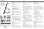
CLIPLINE
Anwenderhandbuch/User Manual
UM IA WF 1000
Art.-Nr./Order No. 2910758
Abisolierautomat WF 1000 und WF 1000 120V
WF 1000 and WF 1000 120V stripping machine
Deutsch
CLIPLINE
Anwenderhandbuch
Abisolierautomat WF 1000 und WF 1000 120V
02/2009
Bezeichnung: UM IA WF 1000
Revision:
01
Art.-Nr.:
2910758
Dieses Handbuch ist gültig für:
Bezeichnung
Revision
Art.-Nr.
WF 1000
1212149
WF 1000 120V
1212258
103896_ia_01
PHOENIX CONTACT
WF 1000
Bitte beachten Sie folgende Hinweise
Damit Sie das in diesem Handbuch beschriebene Produkt sicher einsetzen können, müssen Sie dieses Handbuch gelesen und verstanden haben. Die folgenden Hinweise geben
Ihnen eine erste Orientierung zum Gebrauch des Handbuchs.
Zielgruppe des Handbuchs
Der in diesem Handbuch beschriebene Produktgebrauch richtet sich ausschließlich an
Elektrofachkräfte oder von Elektrofachkräften unterwiesene Personen, die mit den
geltenden Normen und sonstigen Vorschriften zur Elektrotechnik und insbesondere mit den
einschlägigen Sicherheitskonzepten vertraut sind.
Für Fehlhandlungen und Schäden, die an Produkten von Phoenix Contact und Fremdprodukten durch Missachtung der Informationen dieses Handbuchs entstehen, übernimmt
Phoenix Contact keine Haftung.
Erklärungen zu den verwendeten Symbolen und Signalwörtern
Dieses Symbol kennzeichnet Gefahren, die zu Personenschäden führen können. Beachten Sie alle Hinweise, die mit diesem Hinweis gekennzeichnet
sind, um mögliche Personenschäden zu vermeiden.
GEFAHR
Hinweis auf eine gefährliche Situation, die – wenn sie nicht vermieden wird – einen
Personenschaden bis hin zum Tod zur Folge hat.
WARNUNG
Hinweis auf eine gefährliche Situation, die – wenn sie nicht vermieden wird – einen
Personenschaden bis hin zum Tod zur Folge haben kann.
VORSICHT
Hinweis auf eine gefährliche Situation, die – wenn sie nicht vermieden wird – eine
Verletzung zur Folge haben kann.
Die folgenden Symbole weisen Sie auf Gefahren hin, die zu Sachschäden führen können
oder stehen vor Tipps.
ACHTUNG
Dieses Symbol und der dazugehörige Text warnen vor Handlungen, die einen Schaden
oder eine Fehlfunktion des Gerätes, der Geräteumgebung oder der Hard- bzw. Software
zur Folge haben können.
Dieses Symbol und der dazugehörige Text vermitteln zusätzliche Informationen, wie z. B.
Tipps und Ratschläge für den effizienten Geräteeinsatz oder die Software-Optimierung.
Es wird ebenso eingesetzt, um Sie auf weiterführende Informationsquellen (wie Handbücher oder Datenblätter) hinzuweisen.
PHOENIX CONTACT
103896_ia_01
Phoenix Contact behält sich das Recht vor, die technische Dokumentation und die in den
technischen Dokumentationen beschriebenen Produkte jederzeit ohne Vorankündigung zu
ändern, zu korrigieren und/oder zu verbessern, soweit dies dem Anwender zumutbar ist.
Dies gilt ebenfalls für Änderungen, die dem technischen Fortschritt dienen.
Der Erhalt von technischer Dokumentation (insbesondere von Datenblättern, Montageanleitungen, Handbüchern etc.) begründet keine weitergehende Informationspflicht von
Phoenix Contact über etwaige Änderungen der Produkte und/oder technischer Dokumentation. Anderslautende Vereinbarungen gelten nur, wenn sie ausdrücklich von
Phoenix Contact in schriftlicher Form bestätigt sind. Bitte beachten Sie, dass die übergebene Dokumentation ausschließlich eine produktbezogene Dokumentation ist und Sie
somit dafür eigenverantwortlich sind, die Eignung und den Einsatzzweck der Produkte in
der konkreten Anwendung, insbesondere im Hinblick auf die Befolgung der geltenden
Normen und Gesetze, zu überprüfen. Obwohl Phoenix Contact stets mit der notwendigen
Sorgfalt darum bemüht ist, dass die Informationen und Inhalte korrekt und auf dem aktuellen
Stand der Technik sind, können die Informationen technische Ungenauigkeiten und/oder
Druckfehler enthalten. Phoenix Contact gibt keine Garantien in Bezug auf die Genauigkeit
und Richtigkeit der Informationen. Sämtliche der technischen Dokumentation zu entnehmenden Informationen werden ohne jegliche ausdrückliche, konkludente oder stillschweigende Garantie erteilt. Sie enthalten keinerlei Beschaffenheitsvereinbarungen, beschreiben keine handelsübliche Qualität und stellen auch keine Eigenschaftszusicherung oder
Zusicherung im Hinblick auf die Eignung zu einem bestimmten Zweck dar.
Phoenix Contact übernimmt keine Haftung oder Verantwortung für Fehler oder Auslassungen im Inhalt der technischen Dokumentation (insbesondere Datenblätter, Montageanleitungen, Handbücher etc.).
Die vorstehenden Haftungsbegrenzungen und -ausschlüsse gelten nicht, soweit zwingend
gehaftet wird, z. B. nach dem Produkthaftungsgesetz, in Fällen des Vorsatzes, der groben
Fahrlässigkeit, wegen der Verletzung des Lebens, des Körpers oder der Gesundheit oder
wegen der Verletzung wesentlicher Vertragspflichten. Der Schadensersatzanspruch für die
Verletzung wesentlicher Vertragspflichten ist jedoch auf den vertragstypischen, vorhersehbaren Schaden begrenzt, soweit nicht Vorsatz oder grobe Fahrlässigkeit vorliegt oder
wegen der Verletzung des Lebens, des Körpers oder der Gesundheit gehaftet wird. Eine
Änderung der Beweislast zum Nachteil des Anwenders ist mit dieser Regelung nicht verbunden.
103896_ia_01
PHOENIX CONTACT
Deutsch
Allgemeine Nutzungsbedingungen für Technische Dokumentation
WF 1000
Erklärungen zu den rechtlichen Grundlagen
Dieses Handbuch ist einschließlich aller darin enthaltenen Abbildungen urheberrechtlich
geschützt. Jede Drittverwendung dieses Handbuchs ist verboten. Die Reproduktion,
Übersetzung und öffentliche Zugänglichmachung sowie die elektronische und fotografische Archivierung und Veränderung bedarf der schriftlichen Genehmigung der
Firma Phoenix Contact. Zuwiderhandlungen verpflichten zu Schadenersatz.
Alle Rechte für den Fall der Patenterteilung oder Gebrauchsmustereintragung sind
Phoenix Contact vorbehalten. Fremdprodukte werden stets ohne Vermerk auf Patentrechte
genannt. Die Existenz solcher Rechte ist daher nicht auszuschließen.
So erreichen Sie uns
Internet
Aktuelle Informationen zu Produkten von Phoenix Contact und zu unseren Allgemeinen
Geschäfts- und Garantiebedingungen finden Sie im Internet unter:
www.phoenixcontact.com.
Stellen Sie sicher, dass Sie immer mit der aktuellen Dokumentation arbeiten.
Diese steht unter der folgenden Adresse zum Download bereit:
www.phoenixcontact.de/download.
Ländervertretungen
Bei Problemen, die Sie mit Hilfe dieser Dokumentation nicht lösen können, wenden Sie sich
bitte an Ihre jeweilige Ländervertretung.
Die Adresse erfahren Sie unter www.phoenixcontact.com.
Herausgeber
PHOENIX CONTACT GmbH & Co. KG
Flachsmarktstraße 8
32825 Blomberg
DEUTSCHLAND
Telefon
+49 - (0) 52 35 - 3-00
Telefax
+49 - (0) 52 35 - 3-4 12 00
Wenn Sie Anregungen und Verbesserungsvorschläge zu Inhalt und Gestaltung unseres
Handbuchs haben, würden wir uns freuen, wenn Sie uns Ihre Vorschläge zusenden an:
tecdoc@phoenixcontact.com
PHOENIX CONTACT
103896_ia_01
Inhaltsverzeichnis
2
3
4
A
Grundlegende Hinweise .........................................................................................................1-1
1.1
Es geht um Ihre Sicherheit ................................................................................. 1-1
1.2
Gefahren beim Umgang mit der Maschine .........................................................1-1
1.3
Bestimmungsgemäße Verwendung ..................................................................1-2
1.4
Arbeitsplätze ......................................................................................................1-2
1.5
Schutzeinrichtungen...........................................................................................1-2
1.6
Zugelassene Bediener ....................................................................................... 1-3
1.7
Gewährleistung .................................................................................................. 1-3
Beschreibung des WF 1000 ....................................................................................................2-1
2.1
Lieferumfang ......................................................................................................2-1
2.2
Verwendungsbereich des WF 1000 ................................................................... 2-1
2.3
Übersicht über die Bedienteile............................................................................ 2-2
2.4
Funktion der Bedienteile .................................................................................... 2-3
WF 1000 in Betrieb nehmen und bedienen .............................................................................3-1
3.1
Aufstellungsort wählen ....................................................................................... 3-1
3.2
WF 1000 anschließen/einschalten .....................................................................3-1
3.3
Abisolieren.......................................................................................................... 3-2
3.3.1
Durchmesser einstellen ...................................................................... 3-2
3.3.2
Durchmesser korrigieren .....................................................................3-3
3.3.3
Abisolierlänge einstellen .....................................................................3-4
3.3.4
Abzuglänge einstellen ......................................................................... 3-4
3.3.5
Abisolieren .......................................................................................... 3-5
3.3.6
Abfallschale leeren .............................................................................3-6
3.3.7
Zähler auf Null setzen (Reset) ............................................................. 3-7
3.3.8
Außer Betrieb setzen ..........................................................................3-8
Störungen beheben ................................................................................................................4-1
4.1
Störungen und Display-Anzeigen .......................................................................4-1
4.2
Messer wechseln ............................................................................................... 4-3
4.3
Klemmbacken wechseln.....................................................................................4-4
4.4
Netzsicherung tauschen .....................................................................................4-5
Anhang ................................................................................................................................... A-1
103896_ia_01
A1
Technische Daten ............................................................................................. A-1
A2
Bestelldaten ...................................................................................................... A-1
A3
Konformitätserklärung ....................................................................................... A-2
A4
Stichwortverzeichnis.......................................................................................... A-5
PHOENIX CONTACT
i
Deutsch
1
WF 1000
ii
PHOENIX CONTACT
103896_ia_01
Grundlegende Hinweise
Grundlegende Hinweise
Grundvoraussetzung für den sicherheitsgerechten Umgang und störungsfreien Betrieb des
WF 1000 ist die Kenntnis und Beachtung der Sicherheitshinweise.
1.1
Es geht um Ihre Sicherheit
Die Sicherheitshinweise sind von allen Personen zu beachten, die mit dem WF 1000 arbeiten.
Darüber hinaus sind die für den Einsatzort geltenden Regeln und Vorschriften, insbesondere die Regeln zur Unfallverhütung, zu beachten.
1.2
Gefahren beim Umgang mit der Maschine
Der WF 1000 ist nach anerkannten sicherheitstechnischen Regeln gebaut worden.
Er ist mit Schutzeinrichtungen ausgerüstet.
Dennoch drohen bei Fehlbedienung oder Missbrauch Gefahren für
– die Gesundheit des Bedieners und
– die Maschine.
WARNUNG: Gesundheitsgefahren durch unsachgemäßen Umgang
Der WF 1000 ist nur zu benutzen
– für die bestimmungsgemäße Verwendung und
– in sicherheitstechnisch einwandfreiem Zustand.
Alle Personen, die mit der Inbetriebnahme, Bedienung und Instandhaltung des WF 1000
zu tun haben, müssen
– entsprechend qualifiziert sein und
– dieses Anwenderhandbuch genau beachten.
103896_ia_01
PHOENIX CONTACT
1-1
Deutsch
1
WF 1000
1.3
Bestimmungsgemäße Verwendung
WARNUNG: Der WF 1000 ist ausschließlich für Abisolierarbeiten bestimmt
Der WF 1000 ist ausschließlich zum Abisolieren von ein- und mehrdrähtigen runden Leitern im Querschnittsbereich von 0,08 – 6 mm² (AWG 28 – AWG10) bestimmt.
Sehr harte Isolierungen beschädigen die Abisoliermesser und dürfen nicht bearbeitet
werden.
Keine massive Metallteile und Gegenstände einführen, da diese die Abisoliermesser und
die Klemmbacken beschädigen können.
Veränderungen am WF 1000 sind aus Sicherheitsgründen verboten.
Die Beachtung aller Hinweise und die Einhaltung der vorgeschriebenen Betriebsbedingungen gehören zur bestimmungsgemäßen Verwendung.
1.4
Arbeitsplätze
WARNUNG: Für Betrieb und Lagerung sind zu vermeiden:
– feuchte oder staubige Orte und
– Orte, die hoher Wärme, direkter Sonneneinstrahlung oder niedrigen Temperaturen
ausgesetzt sind (Betriebsbereich: 10 °C bis 40 °C).
WARNUNG: Verschütten Sie keine Flüssigkeiten auf dem WF 1000.
Setzen Sie den WF 1000 keinen starken Erschütterungen und Stößen aus.
1.5
Schutzeinrichtungen
WARNUNG: Der WF 1000 darf nur mit aufgesteckter vollständig intakter Abfallschale betrieben werden, da diese gleichzeitig als Schutzhaube fungiert.
Schalten Sie in Arbeitspausen sowie bei Nichtgebrauch den WF 1000 aus.
Aus Sicherheitsgründen schaltet sich der WF 1000 automatisch aus, wenn Sie die Abfallschale (Schutzhaube) abziehen.
WARNUNG: Ziehen Sie den Netzstecker vor dem Öffnen des Gehäuses.
Ein Schild am Geräteboden weist auf bestehende Gefahren hin.
Bild 1-1
1-2
PHOENIX CONTACT
Hinweis am Gerät
103896_ia_01
Grundlegende Hinweise
Zugelassene Bediener
Deutsch
1.6
Am WF 1000 dürfen nur autorisierte und eingewiesene Bediener arbeiten.
Der Bediener ist im Arbeitsbereich Dritten gegenüber verantwortlich.
Der Betreiber muss
– dem Bediener das Anwenderhandbuch zugänglich machen und
– sich vergewissern, dass der Bediener es gelesen und verstanden hat.
1.7
Gewährleistung
Grundsätzlich gelten unsere „Allgemeinen Verkaufs- und Lieferbedingungen“. Diese stehen dem Betreiber spätestens mit Vertragsabschluss zur Verfügung.
Gewährleistungs- und Haftungsansprüche bei Personen- und Sachschäden sind ausgeschlossen bei Zuwiderhandlung gegen nachfolgende Punkte:
– Nicht bestimmungsgemäße Verwendung des WF 1000
– Unsachgemäße Arbeitsplätze.
– Unsachgemäße und über die in dem Anwenderhandbuch beschriebene hinausgehende Anwendung
– Eigenmächtige bauliche Veränderungen des WF 1000
– Weiterbetreiben des WF 1000 bei festgestellten Störungen
– Unsachgemäß durchgeführte Montagen/Reparaturen
WARNUNG: Verwenden Sie nur Originalersatzteile von Phoenix Contact.
103896_ia_01
PHOENIX CONTACT
1-3
WF 1000
1-4
PHOENIX CONTACT
103896_ia_01
Beschreibung des WF 1000
Beschreibung des WF 1000
2.1
Bild 2-1
1
2
3
Deutsch
2
Lieferumfang
Lieferumfang
Grundgerät WF 1000
Abfallschale (Schutzhaube)
Netzkabel
Betriebsanleitung
2.2
Verwendungsbereich des WF 1000
Der Abisolierautomat WF 1000 dient zum Abisolieren von ein- und mehrdrähtigen runden
Leitern im Querschnittsbereich von 0,08 – 6 mm² (AWG 28 – AWG 10).
103896_ia_01
PHOENIX CONTACT
2-1
WF 1000
2.3
Übersicht über die Bedienteile
Bild 2-2
2-2
PHOENIX CONTACT
Bedienteile
1
Drehknopf Abzuglänge
7
Tragegriff
2
Drehknopf Durchmesser
8
Taste
3
Drehknopf Abisolierlänge
9
Netzschalter
4
Starttaste
10 Netzsicherung
5
LC-Display
11 Netzanschluss
6
Abfallschale (Schutzabdeckung)
12 Manueller Betrieb, Motorachse
103896_ia_01
Beschreibung des WF 1000
Funktion der Bedienteile
Tabelle 2-1
1
Funktion der Bedienteile
Drehknopf
Abzuglänge
Zur Einstellung der Abzuglänge.
2
Drehknopf
Durchmesser
Zur Einstellung des Leiter-Durchmessers
(Einschneidtiefe).
3
Drehknopf
Abisolierlänge
Zur Einstellung der Abisolierlänge.
4
Starttaste
Mit dem Einschieben des Kabels wird die Starttaste
gedrückt und der Abisoliervorgang gestartet.
5
LC-Display
Anzeige von Einstellungen, Meldungen und Fehlern.
6
Abfallschale
(Schutzabdeckung)
Dient gleichzeitig als Schutzabdeckung und Auffangbehälter für die Isolationsreste.
7
Tragegriff
Für den Transport.
8
Taste
Zum Reset des Stückzählers und Quittieren von
Meldungen oder Eingaben.
9
Netzschalter
Schaltet die Stromversorgung ein und aus.
Ist der Wert größer als die Abisolierlänge wird der
Isolationsrest vollständig vom Kabel abgezogen.
Wenn der Wert kleiner ist ergibt sich ein Teilabzug.
Nach dem Einschalten leuchtet das LC-Display.
103896_ia_01
10
Netzsicherungen
Im Netzanschluss integrierte Feinsicherungen
(2 Stück).
11
Netzanschluss
Geräteanschluss für das Netzkabel.
PHOENIX CONTACT
2-3
Deutsch
2.4
WF 1000
2-4
PHOENIX CONTACT
103896_ia_01
WF 1000 in Betrieb nehmen und bedienen
WF 1000 in Betrieb nehmen und bedienen
3.1
Deutsch
3
Aufstellungsort wählen
ACHTUNG: Der Aufstellungsort muss eben und waagerecht sein.
ACHTUNG: Für Betrieb und Lagerung sind zu vermeiden:
– feuchte oder staubige Orte und
– Orte, die hoher Wärme, direkter Sonneneinstrahlung oder niedrigen Temperaturen
ausgesetzt sind (Betriebsbereich: 10 °C bis 40 °C).
3.2
Bild 3-1
WF 1000 anschließen/einschalten
Anschließen.
WARNUNG: Den WF 1000 gibt es in zwei Varianten für 230 V und 120 V. Achten Sie auf
den richtigen Netzanschluss (siehe Typenschild).
•
•
•
103896_ia_01
Stecken Sie die Abfallschale (Schutzabdeckung) auf (1).
Schließen Sie den Netzstecker am Netzanschluss an (2).
Schalten Sie den WF 1000 mit dem Netzschalter ein (3) (I drücken).
Das LC-Display leuchtet.
PHOENIX CONTACT
3-1
WF 1000
3.3
3.3.1
Abisolieren
Durchmesser einstellen
ACHTUNG: Stellen Sie als erstes den Durchmesser des Leiters ein, um eine Beschädigung der Abisoliermesser zu vermeiden.
•
Folgen Sie einem der drei abgebildeten Beispiele.
Bild 3-2
•
•
•
3-2
PHOENIX CONTACT
Durchmesser einstellen
Ermitteln Sie den Durchmesser der Leiter (in mm) und addieren Sie einen Sicherheitsbetrag von 0,4 mm dazu, mit der WF 1000 nicht in die Leiter schneidet.
Im Beispiel: gemessener Durchmesser 0,8 mm + 0,4 mm = 1,20 mm
Alternativ können Sie Leiterquerschnitt (mm²) oder AWG-Werte über die aufgedruckte
Tabelle in den Durchmesser in mm übetragen. Dort ist der Sicherheitsbetrag bereits
eingerechnet.
Stellen Sie über den Drehknopf in der Mitte den ermittelten Wert ein.
103896_ia_01
WF 1000 in Betrieb nehmen und bedienen
•
Durchmesser korrigieren
Prüfen Sie die Schnitttiefe mit einem Probeschnitt und korrigieren Sie bei Bedarf die
Einstellung.
0,1 ... 0,3 mm
Bild 3-3
Durchmesser korrigieren
Der Schnitt soll 0,1 bis 0,3 mm vor dem Leiter stoppen, um ihn nicht zu verletzen.
Tabelle 3-1
Beurteilung der Schnitttiefe
Hinweis
Beurteilung
–
Die Messer haben ausreichen Sicherheitsabstand zum Leiter und trennen die
Isolierung sauber ab.
–
Die Messer schneiden zu tief in den Leiter.
–
Die Messer schneiden die Isolierung zu
wenig ein.
Beispiel
ACHTUNG:
Die Messer können beschädigt
werden.
103896_ia_01
PHOENIX CONTACT
3-3
Deutsch
3.3.2
WF 1000
3.3.3
•
Stellen Sie die gewünschte Abisolierlänge (mm) am linken Drehknopf (2) ein.
Bild 3-4
3.3.4
•
PHOENIX CONTACT
Abisolierlänge einstellen
Abzuglänge einstellen
Stellen Sie die gewünschte Abzuglänge (mm) über den rechten Drehknopf (3) ein.
Der Isolierrest kann je nach Anwendung zum Teil oder vollständig abgezogen werden.
Bild 3-5
3-4
Abisolierlänge einstellen
Abzuglänge einstellen
103896_ia_01
WF 1000 in Betrieb nehmen und bedienen
Abisolieren
ACHTUNG: Schräg eingeführte Leiter können zu Störungen führen.
•
•
•
Führen Sie den Leiter waagerecht in den WF 1000 ein.
Lösen Sie die Starttaste möglichst in der Mitte aus.
Sie können Leiter bis zu einem Leiterquerschnitt von 2,5 mm² bequem waagerecht von
oben in das Gerät einführen.
Bild 3-6
103896_ia_01
Einführen des Leiters
PHOENIX CONTACT
3-5
Deutsch
3.3.5
WF 1000
3.3.6
Abfallschale leeren
ACHTUNG: Achten Sie darauf, dass die Abfallschale nicht zu voll wird.
Bild 3-7
•
3-6
PHOENIX CONTACT
Leeren Sie die Abfallschale regelmäßig, damit es nicht zu Störungen kommt.
103896_ia_01
WF 1000 in Betrieb nehmen und bedienen
•
Drücken Sie die Taste (4) auf der Geräterückseite, um den Zähler auf Null zu setzen.
Bild 3-8
103896_ia_01
Zähler auf Null setzen (Reset)
Zähler auf Null setzen
PHOENIX CONTACT
3-7
Deutsch
3.3.7
WF 1000
3.3.8
•
WF 1000 mit Netzschalter (1) ausschalten (0 drücken) und Netzstecker vom Gerät
trennen (2).
Bild 3-9
3-8
PHOENIX CONTACT
Außer Betrieb setzen
Außer Betrieb nehmen
103896_ia_01
Störungen beheben
Störungen beheben
4.1
Tabelle 4-1
Deutsch
4
Störungen und Display-Anzeigen
Störungen beheben
Display-Anzeige
Ursache
Abhilfe
Das Kabel rutscht während des
Abisoliervorgangs durch die
Klemmbacken
Die Klemmbacken sind verschmutzt und müssen gereinigt
werden.
Die Klemmbacken sind abgenutzt und müssen ausgetauscht werden (siehe „Klemmbacken wechseln“ auf
Seite 4-4).
Das Kabel ist ungeeignet.
Die Messer schneiden nicht rich- Die Einstellungen am Display prüfen
tig ein.
Die Messer sind stumpf und müssen ausgewechselt werden (siehe „Messer wechseln“ auf Seite 4-3).
Das Kabel ist ungeeignet.
Das Messer öffnet sich nicht
mehr.
Die Klingen vorsichtig mit einem flachen Gegenstand zurückschieben. Die Messer müssen dabei leichtgängig zurückschnappen.
WARNUNG: Verletzungsgefahr.
Die Messer sind scharf. Achten Sie darauf,
nicht auf die Schneide zu drücken.
Wenn sich die Messer nicht leicht zurückschieben lassen
müssen die Messer wie beim Messerwechsel ausgebaut
werden (siehe „Messer wechseln“ auf Seite 4-3).
Reste aus dem Abisolierbereich entfernen.
Keine Display-Anzeige
Kein Netzanschluss.
Netzsicherung prüfen und gegebenenfalls austauschen
(siehe „Netzsicherung tauschen“ auf Seite 4-5).
Die Abfallschale fehlt.
Abfallschale aufstecken.
Die Taste muss gedrückt werden.
Drücken Sie die Reset-Taste.
WARNUNG: Verletzungsgefahr.
Der WF 1000 startet mit der Bewegung in seiner Ausgangsposition.
Siehe: „Zähler auf Null setzen (Reset)“ auf Seite 3-7.
103896_ia_01
PHOENIX CONTACT
4-1
WF 1000
Tabelle 4-1
Störungen beheben
Display-Anzeige
Ursache
Abhilfe
Der Sensor für Starttaste spricht
schon beim Einschalten an.
WF 1000 vom Netz trennen und Starttaste vorsichtig mit
Pressluft reinigen.
WF 1000 vom Netz trennen, Starttaste ausbauen und das
Metallrohr mit Pressluft ausblasen
Der Sensor für die vordere Endlage wird beim Start nicht betätigt.
WF 1000 ausschalten. Warten bis die Display-Anzeige erlischt und den WF 1000 wieder einschalten.
Der Sensor für den hinteren
Wendepunkt wird betätigt, obwohl das Gerät in der Startposition stehen sollte.
WF 1000 ausschalten. Warten bis die Display-Anzeige erlischt und den WF 1000 wieder einschalten.
Die maximale Zeit für den Abiso- Einstellungen am Display prüfen.
liervorgang wurde überschritten.
WF 1000 ausschalten. Warten bis die Display-Anzeige erlischt und den WF 1000 wieder einschalten.
4-2
PHOENIX CONTACT
Der maximale Motorstrom wurde
überschritten.
Einstellungen am Display prüfen
Die Abfallschale wurde während
des Arbeitszyklus’ entfernt.
WF 1000 ausschalten. Warten bis die Display-Anzeige erlischt und den WF 1000 wieder einschalten.
WF 1000 ausschalten. Warten bis die Display-Anzeige erlischt und den WF 1000 wieder einschalten.
103896_ia_01
Störungen beheben
Messer wechseln
WARNUNG: Verletzungsgefahr!
Schalten Sie den WF 1000 mit dem Netzschalter aus und ziehen Sie den Netzstecker.
WARNUNG: Verletzungsgefahr!
Die Messer sind scharf. Achten Sie darauf, nicht auf die Schneide zu fassen.
Bild 4-1
•
•
•
103896_ia_01
Messer wechseln
Nehmen Sie die Klemmbacken-Kassette (1) ab.
Nehmen Sie die Messerabdeckung (2) ab.
Wechseln Sie die Abisoliermesser (3) aus.
PHOENIX CONTACT
4-3
Deutsch
4.2
WF 1000
4.3
Klemmbacken wechseln
WARNUNG: Verletzungsgefahr!
Schalten Sie den WF 1000 mit dem Netzschalter aus und ziehen Sie den Netzstecker.
Bild 4-2
•
•
Klemmbacken wechseln
Nehmen Sie die Abdeckungen (5) der Klemmbacken-Kassette (1) ab.
Wechseln Sie die Klemmbacken (4) aus.
ACHTUNG:
Achten Sie beim Zusammenbau auf den lagerichtigen Einbau der Klemmbacken (4) und
der Abdeckungen (5).
•
4-4
PHOENIX CONTACT
Bauen Sie die Abdeckungen wieder an.
103896_ia_01
Störungen beheben
Netzsicherung tauschen
Deutsch
4.4
Bild 4-3
Netzsicherung prüfen
WARNUNG: Verletzungsgefahr!
Der Netzanschluss muss geöffnet werden. Schalten Sie den WF 1000 mit dem Netzschalter aus und ziehen Sie den Netzstecker.
•
•
•
•
•
•
Schalten Sie den WF 1000 mit dem Netzschalter (1) aus (0 drücken).
Ziehen Sie den Netzstecker (2).
Ziehen Sie den Sicherungshalter (3) heraus.
Prüfen Sie die Netzsicherungen (4).
Ersetzen Sie die defekten Netzsicherungen:
– Netzsicherung 230 V – 1,25 A, träge
– Netzsicherung 115 V – 2,5 A, träge
Schieben Sie den Sicherungshalter wieder rein.
WARNUNG: Der Sicherungshalter muss einrasten.
103896_ia_01
PHOENIX CONTACT
4-5
WF 1000
4-6
PHOENIX CONTACT
103896_ia_01
A1
Deutsch
A Anhang
Technische Daten
Technische Daten
Netzanschluss
WF 1000
230 V / 50 Hz
WF 1000 120V
120 V / 60 Hz
Leistungsaufnahme
160 VA
Verarbeitungsquerschnitt
0,08 mm² ... 6 mm²
Außendurchmesser, maximal
6 mm
Abisolierlänge
3 mm ... 20 mm
Teilabzuglänge
2 mm ... 20 mm
Einführlänge + Abisolierlänge
15 mm + x
Abisoliermesser
V-Form
Abisolierzeit/Zyklus
0,2 s ... 0,3 s
Stückzähler
6-stelliges LC-Display, rücksetzbar
Maße (B x H x T)
141 mm x 221 mm x 363 mm
Gewicht Grundgerät
9,5 kg
A2
Bestelldaten
Abisolierautomat
Beschreibung
Typ
Artikel-Nr.
VPE
Abisolierautomat, 230 V-Ausführung, für Leiter und Kabel, starr und flexibel
0,08 – 6 mm² (max. Ø 6 mm), mit integriertem Grafikdisplay
WF 1000
1212149
1
Abisolierautomat, 120 V-Ausführung, für Leiter und Kabel, starr und flexibel
0,08 – 6 mm² (max. Ø 6 mm), mit integriertem Grafikdisplay
WF 1000 120V
1212258
1
Ersatzteile
Beschreibung
Typ
Artikel-Nr.
VPE
Abisoliermesser
WF 1000/SB
1212279
1 Set
Klemmbacken
WF 1000/CJ
1212415
1 Set
1 Set
Starttaste
WF 1000/TR
1212416
Abfallschale
WF 1000/COV
1212417
1 Stück
Netzsicherung 230 V – 1,25 A, träge
–
–
2 Stück
Netzsicherung 115 V – 2,5 A, träge
–
–
2 Stück
103896_ia_01
PHOENIX CONTACT
A-1
WF 1000
A3
A-2
PHOENIX CONTACT
Konformitätserklärung
103896_ia_01
Deutsch
Konformitätserklärung
103896_ia_01
PHOENIX CONTACT
A-3
WF 1000
A-4
PHOENIX CONTACT
103896_ia_01
Stichwortverzeichnis
A
L
Abfallschale ............................................................... 2-2
Abisolierlänge ........................................................... A-1
Drehknopf............................................................. 2-2
Einstellen.............................................................. 3-4
Abisolierzeit .............................................................. A-1
Abzuglänge
Drehknopf............................................................. 2-2
Einstellen.............................................................. 3-4
Arbeitsplätze .............................................................. 1-2
Aufstellungsort ........................................................... 3-1
Außendurchmesser................................................... A-1
Lagerung.................................................................... 1-2
LC-Display ................................................................. 2-2
Leistungsaufnahme .................................................. A-1
Lieferumfang.............................................................. 2-1
B
Bediener .................................................................... 1-3
Bestimmungsgemäße Verwendung ........................... 1-2
Betrieb ....................................................................... 1-2
D
Display-Anzeigen .......................................................
Drehknopf
Abisolierlänge.......................................................
Abzuglänge ..........................................................
Durchmesser........................................................
Durchmesser
Ändern..................................................................
Drehknopf.............................................................
M
Maße......................................................................... A-1
Messer wechseln ....................................................... 4-3
N
Netzanschluss .......................................................... A-1
Netzsicherung............................................................ 2-2
Tauschen ............................................................. 4-5
R
Reset-Taste ............................................................... 3-7
S
4-1
2-2
2-2
2-2
3-3
2-2
E
Schutzeinrichtungen .................................................. 1-2
Sicherung defekt ........................................................ 4-5
Starttaste ................................................................... 2-2
Störungen .................................................................. 4-1
Stückzähler ............................................................... A-1
T
Taste.......................................................................... 2-2
Teilabzuglänge ......................................................... A-1
Ersatzteile ................................................................. A-1
V
G
Verarbeitungsquerschnitt .......................................... A-1
Verwendungsbereich ................................................. 2-1
Gewährleistung .......................................................... 1-3
Gewicht..................................................................... A-1
H
Z
Zähler......................................................................... 3-7
Hinweise .................................................................... 1-1
K
Klemmbacken wechseln ............................................ 4-4
Konformitätserklärung............................................... A-2
103896_ia_01
PHOENIX CONTACT
A-5
Deutsch
A4
WF 1000
A-6
PHOENIX CONTACT
103896_ia_01
CLIPLINE
User Manual
English
WF 1000 and WF 1000 120V stripping machine
02/2009
Designation:
UM IA WF 1000
Revision:
01
Order No.:
2910758
This user manual is valid for:
Designation
Version
Order No.
WF 1000
1212149
WF 1000 120V
1212258
103896_ia_01
PHOENIX CONTACT
WF 1000
Please observe the following notes
In order to ensure the safe use of the product described, you have to read and understand
this manual. The following notes provide information on how to use this manual.
User group of this manual
The use of products described in this manual is oriented exclusively to qualified electricians
or persons instructed by them, who are familiar with applicable standards and other
regulations regarding electrical engineering and, in particular, the relevant safety concepts.
Phoenix Contact accepts no liability for erroneous handling or damage to products from
Phoenix Contact or third-party products resulting from disregard of information contained in
this manual.
Explanation of symbols used and signal words
This is the safety alert symbol. It is used to alert you to potential personal injury
hazards. Obey all safety messages that follow this symbol to avoid possible
injury or death.
DANGER
This indicates a hazardous situation which, if not avoided, will result in death or serious
injury.
WARNING
This indicates a hazardous situation which, if not avoided, could result in death or serious
injury.
CAUTION
This indicates a hazardous situation which, if not avoided, could result in minor or
moderate injury.
The following types of messages provide information about possible property damage and
general information concerning proper operation and ease-of-use.
NOTE
This symbol and the accompanying text alerts the reader to a situation which may cause
damage or malfunction to the device, either hardware or software, or surrounding
property.
This symbol and the accompanying text provides additional information to the reader. It is
also used as a reference to other sources of information (manuals, data sheets, literature)
on the subject matter, product, etc.
PHOENIX CONTACT
103896_ia_01
WF 1000
General terms and conditions of use for technical documentation
The receipt of technical documentation (in particular data sheets, installation instructions,
manuals, etc.) does not constitute any further duty on the part of Phoenix Contact to furnish
information on alterations to products and/or technical documentation. Any other
agreement shall only apply if expressly confirmed in writing by Phoenix Contact. Please
note that the supplied documentation is product-specific documentation only and that you
are responsible for checking the suitability and intended use of the products in your specific
application, in particular with regard to observing the applicable standards and regulations.
Although Phoenix Contact makes every effort to ensure that the information content is
accurate, up-to-date, and state-of-the-art, technical inaccuracies and/or printing errors in
the information cannot be ruled out. Phoenix Contact does not offer any guarantees as to
the reliability, accuracy or completeness of the information. All information made available
in the technical data is supplied without any accompanying guarantee, whether expressly
mentioned, implied or tacitly assumed. This information does not include any guarantees
regarding quality, does not describe any fair marketable quality, and does not make any
claims as to quality guarantees or guarantees regarding the suitability for a special purpose.
Phoenix Contact accepts no liability or responsibility for errors or omissions in the content
of the technical documentation (in particular data sheets, installation instructions, manuals,
etc.).
The aforementioned limitations of liability and exemptions from liability do not apply, in so
far as liability must be assumed, e.g., according to product liability law, in cases of
premeditation, gross negligence, on account of loss of life, physical injury or damage to
health or on account of the violation of important contractual obligations. Claims for
damages for the violation of important contractual obligations are, however, limited to
contract-typical, predictable damages, provided there is no premeditation or gross
negligence, or that liability is assumed on account of loss of life, physical injury or damage
to health. This ruling does not imply a change in the burden of proof to the detriment of the
user.
103896_ia_01
PHOENIX CONTACT
English
Phoenix Contact reserves the right to alter, correct, and/or improve the technical
documentation and the products described in the technical documentation at its own
discretion and without giving prior notice, insofar as this is reasonable for the user. The
same applies to any technical changes that serve the purpose of technical progress.
WF 1000
Statement of legal authority
This manual, including all illustrations contained herein, is copyright protected. Use of this
manual by any third party is forbidden. Reproduction, translation, and public disclosure, as
well as electronic and photographic archiving or alteration requires the express written
consent of Phoenix Contact. Violators are liable for damages.
Phoenix Contact reserves all rights in the case of patent award or listing of a registered
design. Third-party products are always named without reference to patent rights. The
existence of such rights shall not be excluded.
How to contact us
Internet
Up-to-date information on Phoenix Contact products and our Terms and Conditions can be
found on the Internet at:
www.phoenixcontact.com.
Make sure you always use the latest documentation.
It can be downloaded at:
www.phoenixcontact.net/download.
Subsidiaries
Published by
If there are any problems that cannot be solved using the documentation, please contact
your Phoenix Contact subsidiary.
Subsidiary contact information is available at www.phoenixcontact.com.
.
PHOENIX CONTACT GmbH & Co. KG
Flachsmarktstraße 8
32825 Blomberg
Germany
Phone +49 - (0) 52 35 - 3-00
Fax
+49 - (0) 52 35 - 3-4 12 00
PHOENIX CONTACT
P.O. Box 4100
Harrisburg, PA 17111-0100
USA
Phone +1-717-944-1300
Should you have any suggestions or recommendations for improvement of the contents and
layout of our manuals, please send your comments to
tecdoc@phoenixcontact.com.
PHOENIX CONTACT
103896_ia_01
Table of Contents
2
3
4
A
Basic information ....................................................................................................................1-1
1.1
Your safety ........................................................................................................1-1
1.2
Dangers when handling the machine..................................................................1-1
1.3
Intended use .....................................................................................................1-2
1.4
Workplaces ........................................................................................................1-2
1.5
Safety equipment ...............................................................................................1-2
1.6
Permitted operators ............................................................................................1-3
1.7
Warranty.............................................................................................................1-3
Description of the WF 1000 .....................................................................................................2-1
2.1
Scope of supply..................................................................................................2-1
2.2
Scope of use of the WF 1000 .............................................................................2-1
2.3
Overview of the actuators ...................................................................................2-2
2.4
Function of the actuators ...................................................................................2-3
Starting up and operating the WF 1000 ...................................................................................3-1
3.1
Selecting the setup location................................................................................3-1
3.2
Connecting/switching on the WF 1000 ...............................................................3-1
3.3
Stripping .............................................................................................................3-2
3.3.1
Setting the diameter ............................................................................3-2
3.3.2
Correcting the diameter ......................................................................3-3
3.3.3
Setting the stripping length ..................................................................3-4
3.3.4
Setting the removal length ..................................................................3-4
3.3.5
Stripping .............................................................................................3-5
3.3.6
Emptying the receptacle tray ...............................................................3-6
3.3.7
Resetting the counter to zero (reset) ...................................................3-7
3.3.8
Stopping the machine .........................................................................3-8
Troubleshooting ......................................................................................................................4-1
4.1
Errors and displays.............................................................................................4-1
4.2
Replacing the blades .........................................................................................4-3
4.3
Replacing the clamping jaws ..............................................................................4-4
4.4
Replacing the mains fuse ...................................................................................4-5
Appendix ................................................................................................................................ A-1
103896_ia_01
A1
Technical data ................................................................................................... A-1
A2
Ordering data .................................................................................................... A-1
A3
Declaration of conformity................................................................................... A-2
A4
Index.................................................................................................................. A-5
PHOENIX CONTACT
i
English
1
WF 1000
ii
PHOENIX CONTACT
103896_ia_01
Basic information
1
Basic information
For safe handling and trouble-free operation of the WF 1000, you must be familiar with and
observe the safety notes.
Your safety
The safety notes must be observed by all persons working with the WF 1000.
Furthermore, the relevant rules and regulations, especially for accident prevention, must
be observed.
1.2
Dangers when handling the machine
The WF 1000 complies with the recognized safety-related rules and regulations.
It is equipped with safety equipment.
However, in the event of operating errors or misuse there is a danger to:
– The operator's health
– The machine
WARNING: Danger to health due to incorrect usage
The WF 1000 must only be used:
– For its intended purpose
– While in safe and proper working order
All persons responsible for starting up, operating, and maintaining the WF 1000 must:
– Be appropriately qualified
– Closely observe this user manual
103896_ia_01
PHOENIX CONTACT
1-1
English
1.1
WF 1000
1.3
Intended use
WARNING: The WF 1000 is designed exclusively for stripping
The WF 1000 is designed exclusively for stripping single and multi-strand circular
conductors in the cross-section range 0.08 - 6 mm² (28 - 10 AWG).
Very hard insulation will damage the stripping blades and must not be used.
Do not insert any solid metal parts or objects, as these can damage the stripping blades
and clamping jaws.
Changes to the WF 1000 are not permitted for safety reasons.
Correct usage includes observing all notes and complying with the predefined operating
conditions.
1.4
Workplaces
WARNING: The device should not be operated and stored in:
– Damp or dusty locations
– Locations exposed to high levels of heat, direct sunlight or low temperatures
(operating range: 10°C to 40°C)
WARNING: Do not spill liquid on the WF 1000.
Do not subject the WF 1000 to any strong vibrations and shocks.
1.5
Safety equipment
WARNING: The WF 1000 must only be operated with the receptacle tray fitted and intact,
as this also acts as a protective cover.
Switch off the WF 1000 during a break and when the device is not being used.
For reasons of safety, the WF 1000 automatically switches off when the receptacle tray
(protective cover) is removed.
WARNING: Disconnect the mains plug before opening the housing.
A label on the bottom of the device indicates the dangers present.
Figure 1-1
1-2
PHOENIX CONTACT
Note on the device
103896_ia_01
Basic information
1.6
Permitted operators
The WF 1000 must only be operated by authorized and trained personnel.
Within the working area the operator is responsible for all other persons.
1.7
English
The owner must:
– Provide the operator with the user manual
– Ensure that the operator has read and understood the user manual
Warranty
In general, our "General sales terms and delivery conditions" apply. They are provided to
the owner no later than on conclusion of the contract.
Warranty or liability claims for damage and personal injury will not be accepted in the event
of the following violations:
– Inappropriate use of the WF 1000
– Inappropriate workplaces
– Inappropriate application and application other than that described in the user manual
– Unauthorized modifications to the WF 1000
– Continued operation of the WF 1000 following the detection of malfunctions
– Incorrect assembly/repairs
WARNING: Only use original replacement parts from Phoenix Contact.
103896_ia_01
PHOENIX CONTACT
1-3
WF 1000
1-4
PHOENIX CONTACT
103896_ia_01
Description of the WF 1000
2
Description of the WF 1000
Scope of supply
English
2.1
Figure 2-1
1
2
3
Scope of supply
WF 1000 basic unit
Receptacle tray (protective cover)
Mains cable
Operating instructions
2.2
Scope of use of the WF 1000
The WF 1000 stripping machine is designed exclusively for stripping single and multi-strand
circular conductors in the cross-section range 0.08 - 6 mm² (28 - 10 AWG).
103896_ia_01
PHOENIX CONTACT
2-1
WF 1000
2.3
Overview of the actuators
Figure 2-2
2-2
PHOENIX CONTACT
Actuators
1
Removal length knob
7
Carrier handle
2
Diameter knob
8
Button
3
Stripping length knob
9
Mains switch
4
Start button
10 Mains fuse
5
LCD
11 Mains connection
6
Receptacle tray (protective cover)
12 Manual operation, motor axis
103896_ia_01
Description of the WF 1000
2.4
Function of the actuators
Table 2-1
1
Function of the actuators
Removal length knob
Used to set the removal length.
If this value is greater than the stripping length, the
remaining insulation is completely removed from
the cable. If the value is smaller, the insulation is
partially removed.
Diameter knob
Used to set the conductor diameter
(cutting depth).
3
Stripping length knob
Used to set the stripping length.
4
Start button
When the cable is inserted the start button is
pressed and stripping is started.
5
LCD
Displays settings, messages, and errors.
6
Receptacle tray
(protective cover)
Acts as a protective cover and is also used to catch
the stripped insulation.
7
Carrier handle
Used for transport.
8
Button
Used to reset the counter and acknowledge
messages or entries.
9
Mains switch
Switches the power supply on/off.
10
Mains fuses
Fine fuses integrated in the mains connection
(2 pcs).
11
Mains connection
Device connection for the mains cable.
English
2
The LCD lights up when switched on.
103896_ia_01
PHOENIX CONTACT
2-3
WF 1000
2-4
PHOENIX CONTACT
103896_ia_01
Starting up and operating the WF 1000
3
Starting up and operating the WF 1000
3.1
Selecting the setup location
NOTE: The device must be set up on a level horizontal surface.
3.2
Figure 3-1
English
NOTE: The device should not be operated and stored in:
– Damp or dusty locations
– Locations exposed to high levels of heat, direct sunlight or low temperatures
(operating range: 10°C to 40°C)
Connecting/switching on the WF 1000
Connect
WARNING: The WF 1000 is available in two versions for 230 V and 120 V. Make sure you
use the correct mains connection (see rating plate).
•
•
•
103896_ia_01
Attach the receptacle tray (protective cover) (1).
Connect the mains plug to the mains connection (2).
Switch the WF 1000 on using the mains switch (3) (press I).
The LCD lights up.
PHOENIX CONTACT
3-1
WF 1000
3.3
3.3.1
Stripping
Setting the diameter
NOTE: First, set the diameter of the conductor to prevent damage to the stripping blades.
•
Follow one of the examples illustrated below.
Figure 3-2
•
•
•
3-2
PHOENIX CONTACT
Setting the diameter
Determine the diameter of the conductor (in mm) and add 0.4 mm leeway to ensure
the WF 1000 does not cut into the conductor.
In the example: Measured diameter 0.8 mm + 0.4 mm = 1.20 mm
Alternatively, the conductor cross-section (mm²) or AWG values can be converted into
the corresponding mm diameter value using the printed table. The leeway value is
already included in the calculation.
Set the calculated value via the middle knob.
103896_ia_01
Starting up and operating the WF 1000
3.3.2
Check the cutting depth with a test cut and correct the setting, if necessary.
English
•
Correcting the diameter
0.1 ... 0.3 mm
Figure 3-3
Correcting the diameter
The cut should stop 0.1 to 0.3 mm from the conductor so that it does not damage it.
Table 3-1
Assessing the cutting depth
Note
Assessment
–
There is sufficient safety distance
between the blades and conductor and
the insulation is removed cleanly.
–
The blades cut too deeply into the
conductor.
–
The blades do not cut deep enough into
the insulation.
Example
NOTE:
The blades may
be damaged.
103896_ia_01
PHOENIX CONTACT
3-3
WF 1000
3.3.3
•
Set the desired stripping length (mm) using the left-hand knob (2).
Figure 3-4
3.3.4
•
PHOENIX CONTACT
Setting the stripping length
Setting the removal length
Set the desired removal length (mm) using the right-hand knob (3).
Depending on the application, the remaining insulation can be partially or completely
removed.
Figure 3-5
3-4
Setting the stripping length
Setting the removal length
103896_ia_01
Starting up and operating the WF 1000
3.3.5
Stripping
NOTE: Conductors inserted at an angle can result in malfunction.
Insert the conductor horizontally in the WF 1000.
Push the start button as close to the center as possible.
Conductors with a conductor cross-section of up to 2.5 mm² can be easily inserted
horizontally in the device from above.
English
•
•
•
Figure 3-6
103896_ia_01
Inserting the conductor
PHOENIX CONTACT
3-5
WF 1000
3.3.6
Emptying the receptacle tray
NOTE: Make sure that the receptacle tray does not become too full.
Figure 3-7
•
3-6
PHOENIX CONTACT
Empty the receptacle tray regularly to prevent malfunction.
103896_ia_01
Starting up and operating the WF 1000
3.3.7
Press the button (4) on the rear of the device to set the counter to zero.
English
•
Resetting the counter to zero (reset)
Figure 3-8
103896_ia_01
Setting the counter to zero
PHOENIX CONTACT
3-7
WF 1000
3.3.8
•
Switch off the WF 1000 via the mains switch (1) (press 0) and disconnect the mains
plug from the device (2).
Figure 3-9
3-8
PHOENIX CONTACT
Stopping the machine
Stopping the machine
103896_ia_01
Troubleshooting
Troubleshooting
4.1
Table 4-1
Display
Errors and displays
Troubleshooting
Cause
Remedy
The cable slips through the
clamping jaws during stripping.
The clamping jaws are dirty and must be cleaned.
English
4
The clamping jaws are worn and must be replaced (see
"Replacing the clamping jaws" on page 4-4).
The cable is not suitable.
The blades do not cut correctly.
Check the settings on the display.
The blades are blunt and must be replaced (see "Replacing
the blades" on page 4-3).
The cable is not suitable.
The blade no longer opens.
Carefully push back the blades with a flat object. The
blades should snap back smoothly.
WARNING: Risk of injury
The blades are sharp. Make sure that you do
not touch the cutting edge.
If the blades cannot be pushed back smoothly, dismantle
the blades using the same procedure as for blade
replacement (see "Replacing the blades" on page 4-3).
Remove any remaining insulation from the stripping area.
No display
No mains connection.
Check the mains fuse and replace if necessary (see
"Replacing the mains fuse" on page 4-5).
Receptacle tray missing.
Attach receptacle tray.
The button must be pressed.
Press the reset button.
WARNING: Risk of injury
The WF 1000 starts by moving from its initial
position.
See "Resetting the counter to zero (reset)" on page 3-7.
103896_ia_01
PHOENIX CONTACT
4-1
WF 1000
Table 4-1
Troubleshooting
Display
4-2
PHOENIX CONTACT
Cause
Remedy
The sensor for the start button
does not respond properly when
the machine is switched on.
Disconnect the WF 1000 from the mains and carefully
clean the start button with compressed air.
The sensor for the front limit
position is not activated when the
machine is started.
Switch off the WF 1000. Wait until the display goes out and
then switch the WF 1000 back on again.
The sensor for the rear turning
point is activated, even though
the device should be in the start
position.
Switch off the WF 1000. Wait until the display goes out and
then switch the WF 1000 back on again.
The maximum time for the
stripping process was
exceeded.
Check the settings on the display.
The maximum motor current was
exceeded.
Check the settings on the display.
The receptacle tray was
removed during the operating
cycle.
Switch off the WF 1000. Wait until the display goes out and
then switch the WF 1000 back on again.
Disconnect the WF 1000 from the mains, remove the start
button, and clean out the metal tube with compressed air.
Switch off the WF 1000. Wait until the display goes out and
then switch the WF 1000 back on again.
Switch off the WF 1000. Wait until the display goes out and
then switch the WF 1000 back on again.
103896_ia_01
Troubleshooting
4.2
Replacing the blades
WARNING: Risk of injury
Switch off the WF 1000 via the mains switch and disconnect the mains plug.
WARNING: Risk of injury
English
The blades are sharp. Make sure that you do not touch the cutting edge.
Figure 4-1
•
•
•
103896_ia_01
Replacing the blades
Remove the clamping jaw cartridge (1).
Remove the blade cover (2).
Replace the stripping blades (3).
PHOENIX CONTACT
4-3
WF 1000
4.3
Replacing the clamping jaws
WARNING: Risk of injury
Switch off the WF 1000 via the mains switch and disconnect the mains plug.
Figure 4-2
•
•
Replacing the clamping jaws
Remove the covers (5) from the clamping jaw cartridge (1).
Replace the clamping jaws (4).
NOTE:
When assembling, make sure that the clamping jaws (4) and covers (5) are correctly
positioned when installed.
•
4-4
PHOENIX CONTACT
Fit the covers again.
103896_ia_01
Troubleshooting
Replacing the mains fuse
English
4.4
Figure 4-3
Checking the mains fuse
WARNING: Risk of injury
The mains connection must be opened. Switch off the WF 1000 via the mains switch and
disconnect the mains plug.
•
•
•
•
•
•
Switch off the WF 1000 via the mains switch (1) (press 0).
Disconnect the mains plug (2).
Remove the fuse holder (3).
Check the mains fuses (4).
Replace the faulty mains fuses:
– 230 V - 1.25 A mains fuse, slow-blow
– 115 V - 2.5 A mains fuse, slow-blow
Push the fuse holder back in.
WARNING: The fuse holder should snap into place.
103896_ia_01
PHOENIX CONTACT
4-5
WF 1000
4-6
PHOENIX CONTACT
103896_ia_01
A Appendix
A1
Technical data
Technical data
WF 1000
230 V/50 Hz
WF 1000 120V
120 V/60 Hz
Power consumption
English
Mains connection
160 VA
Processing cross-section
0.08 mm² … 6 mm²
Outside diameter, maximum
6 mm
Stripping length
3 mm … 20 mm
Partial removal length
2 mm … 20 mm
Insertion length + stripping length
15 mm + x
Stripping blade
V-form
Stripping time/cycle
0.2 s ... 0.3 s
Counter
6-digit LCD, can be reset
Dimensions (W x H x D)
141 mm x 221 mm x 363 mm
Weight of basic unit
9.5 kg
A2
Ordering data
Stripping machine
Description
Type
Order No.
Pcs./Pkt.
Stripping machine, 230 V version, for conductors and cables, solid and
stranded 0.08 - 6 mm² (maximum Ø 6 mm), with integrated graphic display
WF 1000
1212149
1
Stripping machine, 120 V version, for conductors and cables, solid and
stranded 0.08 - 6 mm² (maximum Ø 6 mm), with integrated graphic display
WF 1000 120V
1212258
1
Description
Type
Order No.
Pcs./Pkt.
Stripping blade
WF 1000/SB
1212279
1 set
Clamping jaws
WF 1000/CJ
1212415
1 set
Replacement parts
Start button
WF 1000/TR
1212416
1 set
Receptacle tray
WF 1000/COV
1212417
1 piece
230 V - 1.25 A mains fuse, slow-blow
–
–
2 pieces
115 V - 2.5 A mains fuse, slow-blow
–
–
2 pieces
103896_ia_01
PHOENIX CONTACT
A-1
WF 1000
A3
A-2
PHOENIX CONTACT
Declaration of conformity
103896_ia_01
English
Declaration of conformity
103896_ia_01
PHOENIX CONTACT
A-3
WF 1000
A-4
PHOENIX CONTACT
103896_ia_01
A4
Index
B
O
Button ........................................................................ 2-2
Operation ................................................................... 1-2
Operators................................................................... 1-3
Outside diameter ...................................................... A-1
C
Counter .............................................................. 3-7, A-1
D
Declaration of conformity .......................................... A-2
Diameter
Knob..................................................................... 2-2
Modify .................................................................. 3-3
Dimensions ............................................................... A-1
Displays ..................................................................... 4-1
E
Errors ......................................................................... 4-1
F
Faulty fuse.................................................................. 4-5
I
Intended use .............................................................. 1-2
K
Knob
Diameter............................................................... 2-2
Removal length .................................................... 2-2
Stripping length .................................................... 2-2
L
Partial removal length ............................................... A-1
Power consumption .................................................. A-1
Processing cross-section.......................................... A-1
R
Receptacle tray .......................................................... 2-2
Removal length
Knob..................................................................... 2-2
Set........................................................................ 3-4
Replacement parts.................................................... A-1
Replacing the blades ................................................. 4-3
Replacing the clamping jaws...................................... 4-4
Reset button .............................................................. 3-7
S
Safety equipment ....................................................... 1-2
Scope of supply ......................................................... 2-1
Scope of use .............................................................. 2-1
Setup location ............................................................ 3-1
Start button ................................................................ 2-2
Storage ...................................................................... 1-2
Stripping length ......................................................... A-1
Knob..................................................................... 2-2
Set........................................................................ 3-4
Stripping time ............................................................ A-1
LCD............................................................................ 2-2
W
M
Mains connection ...................................................... A-1
Mains fuse.................................................................. 2-2
Replace ................................................................ 4-5
Warranty .................................................................... 1-3
Weight ...................................................................... A-1
Workplaces ................................................................ 1-2
N
Notes ......................................................................... 1-1
103896_ia_01
PHOENIX CONTACT
A-5
English
P
WF 1000
A-6
PHOENIX CONTACT
103896_ia_01