1
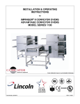
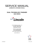
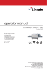
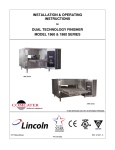
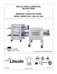
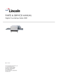
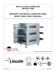
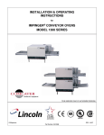
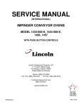
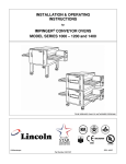
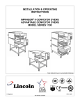
INSTALLATION & OPERATING
INSTRUCTIONS
for
DUAL TECHNOLOGY FINISHER
MODEL 1920 SERIES
TO BE SERVICED ONLY BY AUTHORIZED PERSONS
DTFopsman
P/N: 2810282
REV: 1/5/07
IMPORTANT WARNING AND SAFETY INFORMATION
FOR YOUR SAFETY, DO NOT STORE OR USE GASOLINE OR OTHER FLAMMABLE VAPORS OR
LIQUIDS IN THE VICINITY OF THIS OR ANY OTHER APPLIANCE.
WARNING: IMPROPER INSTALLATION, ADJUSTMENT, ALTERATION, SERVICE OR MAINTENANCE
CAN CAUSE PROPERTY DAMAGE, INJURY OR DEATH. READ THE INSTALLATION, OPERATING,
AND MAINTENANCE INSTRUCTIONS THOUROUGHLY BEFORE INSTALLING OR SERVICING THIS
EQUIPMENT.
• Minimum clearances must be maintained from all walls and combustible materials.
• Keep the Finisher area free and clear of combustible material.
• Adequate clearance for air openings to the control chamber is required.
• Do not obstruct the ventilation holes in the control box and front of the Finisher as these provide
cooling air for the controls.
• The Finisher is to be operated only on the type of electricity as shown on the specification plate.
• This manual should be retained for future reference.
• The electrical wiring diagram is located under the control box cover.
WARRANTY
Lincoln warrants to the original purchaser for use of each Dual Technology Finisher as follows: any
part which proves to be defective in materials or workmanship within the warranty period will, subject
to the terms of this warranty, be repaired or replaced at Lincoln’s option. Repair or replacement is to
be done by the assigned Lincoln Authorized Service Agency. Any claims under this warranty must be
presented in writing to Lincoln through the assigned Authorized Service Agency, promptly and within
the warranty period.
Defective parts of the original equipment are warranted for one year from the date of purchase and
the cost of repair or replacement labor shall be at the expense of Lincoln for one year from the date of
purchase. (Purchase date must be within 24 months of the manufacturing date for the warranty to be
in effect.) If the date of purchase cannot be verified, then warranty shall not exceed 18 months from
the date of manufacture.
This warranty shall not apply if the Finisher or any part is subjected to accident, casualty, alteration,
misuse, abuse, faulty installation, or if the date of manufacture is altered or removed.
The obligation of Lincoln is limited to the above and except as expressly stated herein, Lincoln makes
no guarantee or warranty, express or implied, including without limitation warranties of fitness of
merchant ability with respect to the Dual Technology Finisher and Lincoln has no other liability with
respect thereto including without limitation, liability for incidental, special, or consequential damages.
The following items are not covered by warranty: Any item that is defective because of utility services
(power surges, high and low voltage or improper connections); conveyor belt; replacement of fuses;
adjustments and calibrations for temperatures speed and airflows.
2
DTF – 1920 Series Ops Manual
PURCHASERS RESPONSIBILITY
It is the responsibility of the purchaser:
1. To see that the electric services for the Finisher are installed on site in accordance with the
manufacturers specification.
2. To unload, uncrate, and install the Finisher in its proper location in accordance with this installation
operation manual.
3. To see that the electric services are connected properly by a qualified installer of your choice. All
such connections must be in accordance with applicable code requirements. Refer to page 5 for
specific code references.
TABLE OF CONTENTS
Safety Information…………………………………………………………………………………………. 2
Warranty……………………………………………………………………………………………………. 2
Purchasers Responsibility……………………………………………………………………………..…. 3
Utility Specification………………………………………………………………………………………… 4
Exterior Dimensions………………………………………………………………………………………. 4
Components……………………………………………………………………………………………….. 5
Electrical Grounding Instructions………………………………………………………………………… 5
Spacing…………………………………………………………………………………………………….. 5
Ventilation………………………………………………………………………………………………….. 5
General Information……………………………………………………………………………………….. 5
Uncrating…………………………………………………………………………………………………… 5
Disassembly & Assembly Instructions………………………………………………………………….. 6
Start-Up / Shut Down…………………………………………………………………………………….. 7
Cleaning Instructions……………………………………………………………………………………… 7
Operator Maintenance……………………………………………………………………………………. 8
Preventive Maintenance………………………………………………………………………………….. 8
Information Of Use………………………………………………………………………………………… 8
How To Obtain Service…………………………………………………………………………………… 8
Finger Assembly…………………………………………………………………………………………… 9
Conveyor Removal………………………………………………………………………………………… 10
Conveyor Reassembly……………………………………………………………………………………. 11
Concepts…………………………………………………………………………………………………… 12
UTILITY SPECIFICATION
Model
1921
1922
Input Rate
9 Kw
9 Kw
Voltage
208 VAC
240 VAC
Current
25 Amps
21.7 Amps
Phase
3
3
Hz
60
60
No. of Wires
3 Wires + G
3 Wires + G
Agency Listing
UL, CUL, UL Class.
UL, CUL, UL Class.
NOTE: Do not install these unit(s) in any area with an ambient temperature in excess of 95°F /
35°C. Doing so will cause damage to the unit(s).
DTF – 1920 Series Ops Manual
3
EXTERIOR DIMENSIONS – DUAL TECHNOLOGY FINISHER
23 9/16"
9 25/32"
14 5/32"
Conveyor Opening
2 5/8" High
7 1/4"
53 1/32"
19 29/32"
23 9/32 "
15 27/32"
6 3/16"
COMPONENTS
U
ANGLE PLUG – 30 AMP, 250 VAC, 3 PHASE, NEMA 15-30P
4” LEG
4
DTF – 1920 Series Ops Manual
ELECTRICAL GROUNDING INSTRUCTIONS
Models 1921 and 1922
!
WARNING
This appliance is equipped with a four-prong (grounding) plug for your protection against shock
hazard and should be plugged directly into a properly grounded four-prong receptacle. Do not cut or
remove the grounding prong from this plug.
ELECTRICAL CODE REFERENCE
IN USA
When installed, this appliance must be electrical grounded and its installation must comply with the
National Electric Code, ANSI-NFPA 70, latest version, the Manufacturer’s Installation Instructions, and
applicable municipal building codes.
IN CANADA
All electrical connections are to be made in accordance with CSA C22.1 Canadian Electrical Code
Part 1 and/or Local Codes.
SPACING
The unit must have 6 inches of clearance from combustible surfaces. In case other equipment is
located on the right side of the unit, a minimum clearance of 24 inches is required from that
equipment.
FOR ALL UNITS: A 24-inch clearance at the rear of the unit must be obtainable for service access.
VENTILATION
Local codes prevail. These are the “authority having jurisdiction” as stated by the NATIONAL FIRE
PROTECTION ASSOCIATION, INC> in NFPA 96-1994.
GENERAL INFORMATION
The instructions that follow are intended as a guide for preparing for the installation of the Lincoln
Impinger Finisher unit.
First and foremost, each crate should be examined before signing the Bill of Lading to report any
visible damage caused by the trucker in transit, and account for the number of crates.
IF THERE IS APPARENT DAMAGE: United States and Canada: arrangements should be made to file
a claim against the carrier. As Interstate Commerce Regulations require that the consignee must
initiate the claim.
Proper and secure storage facilities should be arranged for the unit(s), if necessary to protect it from
outdoor or damp conditions at all times before installation.
UNCRATING
DO NOT LIFT EXCESSIVE WEIGHT
When you have all the crates unloaded, open the crates and remove any protective packaging.
Inspect at once for concealed damage. If anything appears to be damaged, contact the appropriate
persons immediately to file a damage claim. After completing this inspection, finish unpacking the
unit(s) and all other components.
DTF – 1920 Series Ops Manual
5
DISASSEMBLY & ASSEMBLY INSTRUCTIONS
OTHER THAN OPTIONAL LEGS, THIS UNIT WHEN RECEIVED IS READY FOR OPERATION
AFTER BEING PLUGGED INTO AN ELECTRICAL SOURCE.
!
CAUTION:
Unit must be cool before proceeding with disassembly. Switch unit off and
disconnect from the power supply.
1. Remove left and right crumb pans by lifting the outside edge upwards and then sliding off.
2. Remove conveyor (see page 10).
3. Remove the top and bottom air wash assemblies. The top and bottom assemblies are not
interchangeable so mark proper orientation. Each of these are attached by two ¼-turn fasteners.
4. Remove the bottom finger assemblies by sliding out each side. These are marked “LS” (left side)
and “RS” (right side).
5. Remove the top finger assembly. This can be removed from either side.
6. Reassemble in reverse order.
6
DTF – 1920 Series Ops Manual
START-UP
1. Push both the “Impingement” and the “Standby” switches to the “ON” position. The electric oven
should come on immediately. The “Impingement” switch controls the heating elements for the
main blower fan and the “Standby” switch controls the infrared heating elements and the
conveyor.
2. Preheat the oven for 30 minutes.
3. Program the unit to desired settings. To enter the program mode,
the TIME and TEMPERATURE buttons must be pressed
simultaneously and held for 2 to 3 seconds.
a. Press the TIME button to program AM and PM
preset times (1 each). Each pressing of the TIME button will
toggle between AM and PM settings. Use the UP and
DOWN buttons to achieve the desired setting for AM and
PM.
b. Press the TEMPERATURE button to program
AM and PM preset temperatures (1 each). Each pressing of
the TEMPERATURE button will toggle between AM and PM
settings. Use the UP and DOWN buttons to achieve the desired settings for AM & PM.
c. In steps A and B, exiting in the AM will place the control in the AM mode while
exiting in PM will place the control in the PM mode.
Factory defaults: AM = 0:24 seconds and 650°F while PM = 0:39 seconds and 600°F.
4. To switch the control from one mode to the other requires that the operator press and hold the
desired AM or PM buttons for 2 to 3 seconds. On power reset, the control will re-enter the last
selected mode.
SHUT DOWN
1. Push both switches (Impingement and Standby) to the “OFF” position. The unit’s main fan will run
for 30 minutes after shutting off in cool down mode.
CLEANING INSTRUCTIONS
The Lincoln Impinger Dual Technology Finisher contains electrical components. Before cleaning the
unit, switch off and disconnect from the electrical supply.
No electrical components should be subjected to moisture. It is, therefore, important that the oven is
wiped down carefully. NEVER throw buckets of water over the oven or subject it to pressure washing
from a hose of pressure spray. If water or other liquid is spilled on the unit, make sure that none has
entered the control box area before switching on. If in doubt, call your local service company.
!
CAUTION:
Unit must be cool. Do not use power-cleaning equipment, steel wool, or
wire brushes on stainless steel surfaces.
DAILY
1. Clean exterior surfaces of the unit by wiping it down with a mild detergent and clean water, or a
commercial stainless steel cleaner.
2. Clean the interior by sweeping up all loose particles then wash with a mild detergent solution and
rinse with clean water.
3. Clean the conveyor belt by wiping with a cleaning cloth or brushing with a soft wire brush.
NOTE: DO NOT use a caustic or an alkaline base cleaner on the interior of the unit. This will ruin the
finish of the interior. On the exterior of the unit, removal of deposits of baked-on splatter, oil, grease,
or light discoloration may be removed with any of several commercial cleaners. Consult with your
local supplier.
WEEKLY
1. Remove finger, disassemble and clean. Instructions on page 9.
2. Remove conveyor, disassemble and clean. Instructions on page 10.
DTF – 1920 Series Ops Manual
7
OPERATOR MAINTENANCE
!
WARNING – DANGER:
DISCONNECT POWER SUPPLY BEFORE SERVICING OR CLEANING THIS OVEN.
SAFEGUARD AGAINST POWER SO IT CANNOT BE ACCIDENTALLY RESTORED. FAILURE TO
DO SO COULD RESULT IN DISMEMBERMENT, ELECTROCUTION, OR FATAL INJURY.
Extensive engineering went into this unit to make it as maintenance free as possible. There is no
lubrication required.
However, to achieve the maximum efficiency of the unit, it is necessary to keep it clean. For cleaning
instructions, see page 7. The frequency listed is only the factory’s recommendation. Your use and
type of products will actually determine the frequency of cleaning.
If the unit fails to operate, check the circuit breaker to be sure it is turned on. Also check the fuses
and resets on the back side panel to be sure that they are good before you call the Authorized Service
Agency. The name and phone number of the Authorized Service Agency should be located on the
oven or contact the factory at (800) 678-9511 for the name of the nearest Authorized Service Agency.
PREVENTIVE MAINTENANCE
Although this unit has been designed to be as trouble free as possible, periodic preventive
maintenance is essential to maintain peek performance. It is necessary to keep motors, fans, and
electronics free of dirt, dust and debris to insure proper cooling. Overheating is detrimental to the life
of all components mentioned.
The periodic intervals of preventive cleaning may vary greatly depending upon the environment in
which the unit is operating.
You must discuss this need for preventive maintenance with your Authorized Service Company to
establish a proper program.
If there are any questions that the Service Company cannot answer, contact Lincoln’s Technical
Service Department at (800) 678-9511.
INFORMATION ON USE OF UNIT
As explained in “Concepts” (page 12), the Lincoln Impinger DTF functions by directing high velocity
streams of heated air directly upon the food products. Because air and infrared are the heat sources,
it is effective even on sensitive foods. Compared two conventional ovens and even convection ovens,
the cooking time of products in the DTF can be two (2) to four (4) times faster. Several factors may
affect the cooking time of any special products such as:
1. Unit temperature setting
2. Conveyor speed
HOW TO OBTAIN SERVICE
If the unit fails to operate, check the circuit breaker to be sure it is turned on. Also check the fuses
and resets on the back side panel to be sure that they are good before you call the Authorized Service
Agency. The name and phone number of the Authorized Service Agency should be located on the
oven or contact the factory at (800) 678-9511 for the name of the nearest Authorized Service Agency.
8
DTF – 1920 Series Ops Manual
FINGER ASSEMBLY
BOTTOM FINGERS
TOP FINGER
DISASSEMBLE FINGERS FOR CLEANING
1. Slide finger cover from the housing. Lift out inner columnating panel.
REASSEMBLY
1. When reassembling make sure the bent edge of the columnating panel is facing the finger cover.
2. Reinstall fingers in the unit. Be sure they are seated over the plenum flanges and the holes are
pointed toward the conveyor.
DTF – 1920 Series Ops Manual
9
CONVEYOR REMOVAL
1. Remove coupling away from drive lugs.
2. Remove conveyor from oven cavity.
3. Reassemble in reverse order.
CONVEYOR DISASSEMBLY FOR CLEANING
Pull conveyor out the right end. Place on table or work surface.
CONNECTING LINKS IN
THREE PLACES
2. Locate connecting links on the conveyor
belt, turn belt to place the links on the
top left end of the conveyor
approximately 8'
’from the shaft.
Also notice the direction of the opening on
the other links. The belt will have to be
reinstalled with the opening facing the same
way.
3. You can easily remove the connecting
links by grasping them with a pair of
pliers and slipping the eye of the
connecting link over the wire of the other
links.
1. Carefully pull out the belt, rolling it up as
you go. After you have removed it, it
may be placed in a pan of detergent
solution to soak. Rinse with clean
water.
10
DTF – 1920 Series Ops Manual
CONVEYOR REASSEMBLY
CONVEYOR BELT INSTALLATION
1. Put conveyor belt back on by setting the rolled belt to the left of the conveyor and thread
approximately 2/3 of the belt over the bottom of the slider bed.
2. Put the loose end of the belt around the idler shaft and back on the conveyor. The belt must lie on
top of the upper conveyor slider bed.
NOTE: The belt should curl around the conveyor sprockets and lay flat on top of the sprockets. If the
belting does not curl around the sprockets and lay flat, remove the belting and turn over. Reinstall.
3. Pull all of the slack belt through the conveyor until both ends are on top of the conveyor on the left
end.
4. Reconnect the conveyor belt by slipping the connecting links back in place.
NOTE: The conveyor belt of the Impinger DTF does not have a tension adjustment. If the belt would
become too loose, a link(s) will have to be removed to tighten. A belt that is too tight will also cause
operational problems due to excessive drag. We suggest that you have a qualified service person
perform this adjustment.
!
WARNING:
Careful consideration should be exercised prior to removing a
belt link because a belt that is too tight will impede the smooth
operation of the conveyor.
!
CAUTION:
Do not work around conveyor belt with long hair, loose clothing,
or dangling jewelry. Getting caught in the belt could result in
dismemberment or fatal injury.
!
CAUTION:
BELT MAY BE HOT!
DTF – 1920 Series Ops Manual
11
CONCEPTS
The Dual Technology Finisher produced by Lincoln Impinger utilizes a revolutionary cooking concept
called “AIR IMPINGEMENT” which is combined with the additional heat source of “INFRARED”
heating elements. It provides exceptional baked food quality in far less time than conventional
devices on the market. The Dual Technology system directs a high velocity stream of heated air at
the food product being baked. This blast effect penetrates the boundary layer of air encircling the
product and heats the food more efficiently because the air concentrates heat on the product. Greater
heat transfer rates, which result in products baking two to four times faster than conventional means
are possible with dual technology.
The Dual Technology process develops the high velocity air stream with a specially designed fan that
draws superheated air from the heat source (electric). The air is directed through a plenum chamber
to “FINGERS” which have focused ports that “impinge” the heated air onto the product surface. The
heated air is recycled to the heat sources after striking the product thus reducing energy consumption.
This unit is also designed with a cool skin technology for the outside surface.
The Dual Technology process is tolerant enough for sensitive food products and effects proper
crisping and even browning of such products as they pass through the unit because air is the medium
which heats the food product.
Lincoln Foodservice Products, LLC
1111 North Hadley Road
Fort Wayne, Indiana 46804
United States of America
Telephone: (260) 459-8200
U.S. Fax: (888) 790-8193 • Int’l Fax: (260) 436-0735
Service Hotline: (800) 678-9511
www.lincolnfp.com
12
DTF – 1920 Series Ops Manual