1
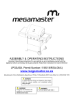
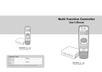
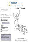
 Installation Manual
T1220 Storage Shelter
v.2 140820 SPECIFICATION
Length: 21.4m
Width: 12.2m
Height: 7.6m
Sidewall height:4.2m
Door dimension: W4.5xH4.5m
IMPORTANT----READ MANUAL FIRST
Improper site preparation, assembly and maintenance may invalidate warranty and cause unnecessary and costly
mistakes. If you have any questions contact your local dealer.
For User Friendly assembly we have identified each individual component with the part code as indicated in the
parts list. Please refer to the part code numbers and drawing to ensure problem free assembly.
It’s necessary to tighten the roof fabric enough to avoid “hammocks”on the roof and also re-tighten once or twice
again after a few months of use. This is important when assembly in cold weather (autumn and winter) because the
fabric is stiff then and when we got the sun and warm weather afterwards it will make the fabric "slack" again
and need to be re-tighten before next winter.
It’s the owners responsibility to take of snow immediately if not slide of by itself.
READ ALL INSTRUCTIONS BEFORE ASSEMBLY
1. Keep work area clean. Cluttered areas invite injuries. Do not set up near snow drifts, in slippery places, in high
winds, or wet location.
2. Keep children away. All children should be kept away from the work area. Be aware of personal safety. Be
careful not to pinch fingers with clips and tubes when assembling: when using makes sure there is adequate
ventilation for exhaust and other dangerous fumes.
3. Do not over reach. Keep proper footing and balance at all times.
4. Do not assemble if under the influence of alcohol or drugs. Read warning labels on prescription to determine if
your judgment or reflexes are impaired while taking drugs. IF there is any doubt, do not assemble.
5. Be aware of possible windy conditions; fasten the base in concrete if these situations may occur. Remove the
cover during hurricane.
6. Be careful with power and heat sources. Do not keep heat sources near the tarpaulin. Do not expose to open
flame.
7.Be aware of personal safety during assembly and use .Be careful not to pinch fingers with clips and tubes when
assembling when using makes sure there is adequate ventilation for exhaust and other dangerous fumes.
1
21.4x12.2x7.6m Part List
Part
Description
QTY
1
Top roof tube
7sets
1A
Top roof tube at front door
1 set
2
Roof curving tube
12sets
2A
Roof curving tube at front door
2sets
3
Lower curving tube
12sets
3A
Lower curving tube at front door
2
3B
Lower curving tube at back door
2
4
Roof curving tube at shoulder height
12
4A
Roof curving tube at front and back door
4
5
Upper standing leg
16
5A
Lower standing leg
16
6
Purlin
77
7
Base flange for standing legs
12
7A
Base flange in left corner
2
7B
Base flange in right corner
2
7C
Base flange with screw
8
Base flange for mechanical door
2
9
Base flange for front and back cover
6
10L
Lower door track for front door at left
1
10R
Lower door track for front door at right
1
11L
Upper door track for front door at left
1
11R
Upper door track for front door at right
1
12
Door beam on front door
12A
Vertical support tube for front door beam
1
13
Lower standing leg at left for front door
1
13A
Lower standing leg at right for front door
1
14
Upper standing leg at front door
2
15
Middle rail at front door
6
15A
Middle rail at front door
2
16
Tube for front Mechanical door
1
20sets
1set
17
Steel wire at side
14
18
Clips to connect steel wire
50
19
Steel wire on top
16
20
Tensioning tube at front door
4
21
Stake Peg
80
22
Tensioning tube for Roof cover
23
Lower standing leg for back door
4
24
Middle standing leg for back door
2
24A
Upper standing leg at side for back door
2
25
Upper standing leg in middle for back door
2
26
Tensioning tube for back cover
5
27
Rail for back door
11
28
Rail at sidewall for back door
2
29
Door tube
7sets
30
Mechanical wheels
1set
31
12X50 bolt for tubes and both doors
192 sets
32
10X80 Bolt for purlin and both doors
88 sets
33
10x90 bolt for both doors
32 sets
34
12x100 bolt
16 sets
35
10X80 Bolt for front door
6sets
36
10X60 Bolt for front door
10
37
10X30
8
38
32mm Plastic cap
22
39
Rope
6
40
Band for tie down ratchet
16
41
Roof cover
1
42
Front cover
1
43
Back cover
1
2 sets
3
Figure 1:Sketch of trussed frame shelter
Size: L21.4xW12.2xH7.6m
4
EQUIPMENT AND TOOLS FOR INSTALLATION
1. Measuring Tape
3. Stake
5. Sledge Hammer
7. Wrench
9. Hoist
2. String for alignment
4. Ladder or Scissors Lift
6. Drill
8.Knife
INSTALLATION PROCESS
A----BASE INSTALLATION
Please refer to the diagram (Figure 2) to place the base plates:
Figure 2 Base Flange
1. The measurement is from center to center of tubes on the base palates. Referring to the above diagram and
confirm the place of base plates. There are four holes on the plates for stake pegs.
Foundation placement
As Figure 2 shows each Base plate is equipped with 4 pieces of Stake pegs with ratchets on.(No.21)
1. Mark the stake peg hold through the base plate by using the stake peg. Move the base plates away and the mark
determines where the stake peg will be.
2. Note: The stake peg apply for normal conditions, not suitable to the rock ground, frozen soil and concrete
ground.
5
B---FRAME INSTALLATION
Figure 3
Figure 4
1.Figure 3 shows to connect the Top roof tube(No.1/1A),Roof curing tube(No.2/2A),Lower curving tube(No.3/3A) ,
Roof curving tube at shoulder (No.4/4A) and Upper standing leg(No.5),Lower standing leg(No.5A)with Bolt
M12x50(No31), then put the arch into tube of the Base flange by hoist, and assemble every group arch by turns(see
Figure 4). Do not install the bolts on the top of the truss where the fabric will rest.
Figure 5
Figure 6
3. Connect Purlin(No.6) to arch by using Bolt 10x80 (No.32) by turns(see Figure 5),then connect the Steel
wire(NO.17 and NO.19) on top and side by using Clip(No.18) (see Figure 6).
Do not tighten down the nuts completely until frame is fully assembled and set in place. the arches, the front
and back panel should be assembled well on the ground before erected into the Base Flanges.
6
C--- INSTALLING FRONT DOOR
Figure 7: Front Door(seeing from outside)
Figure 8:Front Cover(seeing from inside)
D--- INSTALLING BACK DOOR
Figure 9:Back door(seeing from outside)
Figure 10:Back cover (seeing from outside)
7
E--- INSTALLING THE ROOF COVER
NOTE: Do not install the cover onto the frame of your building in high wind conditions.
Figure 11
1. As Figure 11 shows, when Roof cover is over top of Frame assembly (see Figure 11) ,insert Tensioning
tubes(NO.22) into pockets along both sides of Roof cover, connect the Ratchet (Part NO.7C) to the tensioning tube
by part (see Figure 12),then put the plastic cap (NO.38) to end of tensioning tubes.
Figure 12
2. As Figure 12 shows, align one side of Roof cover evenly front to back, add band(No.30) for tie down ratchet at
each point alone the cover opening, Put band for tie down ratchets over cover tensioning tubes at each base
plate alone one side. Bands do not attach to tensioning tubes, but loop around and secure at both ends on
ratchet.
3. The roof cover is tensioned frond front to back by the rope lacing to grommet flaps inside the main cover, inside
the unit at both front and rear arches. using the rope provided, lace the main cover grommet flap around the main
frame front and rear arch pieces. start in the top middle of each arch, and lace to each side. add rope length by tying
pieces together or cutting as necessary.
CONGRATULATIONS:
NOW YOUR ASSEMBLY IS COMPLETED.
8