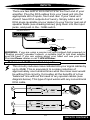
1
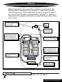
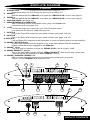
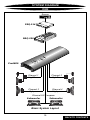
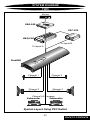
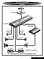
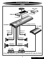
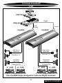
TM
POWERCLASS
PC6800 Owners Manual
CONTENTS
(Click on a topic to view)
Congratulations
Crossover Settings
Features / Specifications
Inputs
TM
QBASS PLUS
Crossover Operation
Installation
Input, Combine, and Gain
Wiring
Troubleshooting
Wiring (continued)
Troubleshooting
Power / Ground
System Diagram 1
Power, Ground and Remote
System Diagram 2
Speaker Wiring
System Diagram 3
Bridging
System Diagram 4
Endplate Diagram
System Diagram 5
Controls Diagram 1
Block Diagram
Controls Diagram 2
Warranty
Congratulations and thank you.....
for choosing PrecisionPower audio epuipment. At PrecisionPower we
proudly design, engineer and manufacture audio products at our facility in
Phoenix, Arizona. Our award winning engineering team utilizes innovative
technology to consistently deliver Absolutely State of the Art performance,
sound quality, reliability, and value. This PrecisionPower product reflects
our commitment to offer you unparalleled versatility and quality for years of
dependable service and listening enjoyment.
TM
S ervice
Do not attempt to service PrecisionPower products yourself.
Performing exploratory surgery on your audio equipment yourself
will void the warranty. Many parts of your PrecisionPower gear
are custom built to our specifications. Our factory parts are not
made available to anyone else nor are they for sale. Our goal
is to make sure that your PrecisionPower product will always
sound as good as the day it was purchased. Contact your
authorized PrecisionPower dealer about obtaining any warranty
service through PrecisionPower.(See Warranty inside back cover)
F O R YO U R R E C O R D S :
M o d e l
Serial Number
Purchase Date
C aution!
The extended use of a high powered audio system may
result in hearing loss or damage. While PrecisionPower
systems are capable of "Concert Level" volumes with
incredible accuracy, they are also designed for you to
enjoy at more reasonable levels all of the sonic subtleties
created by musicians. Please observe all local sound
ordinances.
BACK TO CONTENTS
FEATURES / SPECIFICATIONS
PWM Switching Power Supply
Fully Complementary Triple Darlington Output Stage
AM IV Protection Circuitry
QBASS PLUS™
QBASS REMOTE™ Compatible
PowerLock Speaker and Power Wire Connectors
Variable, 6-Way Internal Crossover
Non-Fading Sub Channels
Balanced Differential Input Stage
High Voltage Input Capability with Input Attenuation Switch
Gold Plated RCA Input and Output Connectors
Mixed Mono/Stereo Operation
Multiple System Configuration
PSC-221 Input Switching
Three Year Warranty when installed by an Authorized
PrecisionPower Dealer
Completely Designed And Handcrafted In The USA
Specifications
Power Bandwidth:
Total Harmonic Distortion:
Input Topology:
Input Sensitivity:
Input Impedance:
Load Impedance (stereo)
Load Impedance (bridged)
Load Impedance (bridged)
Supply Voltage
Damping Factor
Slew Rate
Idle Current:
4.5 Hz - 100 kHz
0.02 %
Differential
150mv - 12 volts RMS
10k Ohms
2 - 8 Ohms
4 - 8 Ohms (Channels 1-4)
2 - 8 Ohms (Channels 5-6)
11 - 15 volts
>500
>50 V/µS
2.25 Amps
C o n t i nu o u s O u t p u t Pow e r
CHANNELS 1/2
50 WRMS x 2 @ 4Ω per channel
100 WRMS x 2 @ 2Ω per channel
200 WRMS x 1 @ 4Ω bridged
CHANNELS 3/4
50 WRMS x 2 @ 4Ω per channel
100 WRMS x 2 @ 2Ω per channel
200 WRMS x 1 @ 4Ω bridged
CHANNELS 5/6
50 WRMS x 2 @ 4Ω per channel
100 WRMS x 2 @ 2Ω per channel
200 WRMS x 2 @ 1Ω per channel
200 WRMS x 1 @ 4Ω bridged
400 WRMS x 1 @ 2Ω bridged
Dimensions
Length - 25.25"
Height - 2.25"
Width - 8.9"
1
BACK TO CONTENTS
QBASS PLUS ™
Q BASS PLUS ™
On POWERCLASS™ amplifiers, we've taken bass control to
a higher level with QBASS PLUS™. The two QBASS
switches (labeled 1 and 2) on the front end of the amplifier
allow you to select one of four frequency centers - 30 Hz,
36 Hz, 44 Hz and 60 Hz. The Q SELECT switch determines
the width of boosted frequencies. A 'Q' of 2 (switch out)
will give you a wide boost while a 'Q' of 4 will boost a
narrow range of frequencies (See chart below). On the
rear end panel you will find the QBASS level control and
the plug-in for an optional QBASS REMOTE™ dash
mounted level control. Adjust the level control clockwise
for up to 18dB of boost at your selected frequency and Q.
Q BASS PLUS ™
Q B A S S ™ Settings
1
2
Freq.
IN
IN
OUT
OUT
IN
OUT
IN
OUT
30Hz
36Hz
44Hz
60Hz
Q=2
Q=4
+18dB
+12dB
+6dB
0dB
30Hz
Optional QBASS REMOTE™
This boost control can be mounted
in the dash and will supersede the
boost control on the endplate.
36Hz
44Hz
60Hz
OT E
EM
QBASS R
™
d in the
ndcrafte
d and ha
Designe
USA
QB
AS
S
™
Optional QPORT™ expansion
0
module allows one boost control
to operate multiple amplifiers. Each
+1
QPORT™ has outputs for four amplifiers 8
as well as another QPORT™ for greater
expansion. See your Authorized PrecisionPower
Dealer for more information!
Crossover Specifications
PC PRO 6800
Linkwitz-Riley crossover topology used throughout.
High Pass (Channels 1/2, 12dB/Octave stereo) Fully Variable 20 Hz - 20 KHz.
Band Pass (Channels 3/4, 12dB/Octave stereo) Fully Variable 20 Hz - 20 KHz.
Sub or Band Pass Channels 5/6, (24dB/Octave mono Fully Variable 50 Hz - 500 Hz
Lowpass or 12dB/Octave stereo 20 Hz - 20 KHz Bandpass).
Sub or Band Pass RCA outputs will be the opposite of Channels 5/6 Crossover.
QBASS PLUS™ on Lowpass assigned to Channels 5/6 or RCA OUTPUT.
CAUTION: QBASS PLUS™
should only be used in systems with strong
subwoofers. 18dB is a lot of bass boost and could damage full range speakers.
2
BACK TO CONTENTS
INSTALLATION
Tools/Parts needed for Installation (not supplied)
Small flat blade screwdriver
Phillips Screwdriver (#2 or medium sized)
Wire cutters
Wire strippers
4 - #6 round head screws, and 1 - #8 sheet metal screw
(or nut, bolt, and star washer)
2 - Ring connectors (large enough to accommodate your
method of grounding)
In-line fuse or circuit breaker - see fuse chart below
Power and ground wire - see Power Wire Calculator on page 3
Speaker wire - 16 gauge or larger
Grommets (sized to work with the power wire you plan to use
in your installation)
Tube of silicone sealant
Fuse requirements
Amplifier
Maximum Fuse Rating
Pro6800
80 Amp
You will need to install an in-line fuse or circuit breaker in
the power wire within 18" of the battery. This fuse or circuit
breaker is to protect your vehicle from fire in case the power
wire shorts to the vehicle body. If you are only using one
amplifier, use the fuse rating indicated in this chart. If you are
using more than one amplifier, add up the fuse ratings for all the
amplifiers. This sum is the rating for your fuse or circuit breaker.
You may also want to add a power distribution block near your
amplifiers to keep the wiring tidy.
3
BACK TO CONTENTS
WIRING
The following is a basic formula to be used as a guide to determine current
draw. A 50% amplifier efficiency rating is used as an average. Your new
POWERCLASS™ amplifier is more efficient, other amplifiers will probably
be less. This formula is to be used as a guideline. Using wire of a larger
gauge can only improve the current transfer of your system. Do not use
smaller gauge wire.
Total RMS output x 2 = Total Input Wattage
Total Input Wattage = Current Draw (in Amps)
Supply Voltage
Example: A POWERCLASS™ Pro6800 amplifier has six channels at 50
watts RMS per channel into 4 Ohms (50 x 6 = 300). You would use the
formula in the following way:
300W x 2 = 600W
600W = 50A Total current draw.
12V
If the same amplifier is driven into a 2 Ohm stereo or 4 Ohm mono load,
double it's 4 Ohm RMS rating. All POWERCLASS™ amplifiers will effectively
double their power at this load.
300W x 2 x 2 = 1200W
1200W = 100A Total current draw.
12V
If you are using more than one amplifier, add up the total current draw
for all of them and choose the appropriate gauge based on the grand total.
Pow e r W i r e C a l c u l a t o r
Recommended MINIMUM Gauge
Total Current Draw
( in Amps)
Up to 4ft.
0-20
20-35
35-50
50-65
65-85
85-105
105-125
125-150
14
12
10
8
6
6
4
2
4 to 7ft.
12
10
8
8
6
6
4
2
Length Of Wire To Be Run
7 to 10ft. 10 to 13ft. 13 to 16ft. 16 to 19ft. 19 to 22ft. 22 to 28ft.
12
8
8
6
4
4
4
2
10
8
6
4
4
2
2
2
10
6
6
4
2
2
2
0
8
6
4
4
2
2
0
0
8
6
4
4
2
2
0
0
8
4
4
2
0
0
0
00
(
NOTE: The ground wire should be the same gauge as the power wire.
4
BACK TO CONTENTS
WIRING
Before beginning, disconnect the negative (-) terminal of the
battery prior to working on the positive (+) terminal to prevent
a short to ground. This is important, unless you want to spend
the rest of your life with a nickname like "Sparky," or "Smokey."
Reconnect the negative terminal only after all connections have
been made.
Factory Ground wire may
need to be replaced if it is
frayed or broken.
Positive
Battery
Terminal
Fuse must be
installed within
18" of battery
Run signal cables (RCAs)
and remote turn-on lead
down the opposite side of
the vehicle of the power
wire to avoid radiated noise.
eject
BASS
LEFT
1
2
5
6
3
4
7
8
Trk 1
TREBLE
BALANCE
VOLUME
TRACK
RIGHT
FOWARD
PPI
MAR
KET
ING
Drill a hole in the firewall
and use a rubber grommet
to keep wire from shorting.
DPT
REVERSE
Run the cables under the
carpet near the side of the
vehicle. Be careful not to
drill or screw into the wires
when you replace the trim.
Avoid sharp edges that
could chafe through the
insulation.
For systems over 300 watts,
add a ground cable from the
amp to the battery
(see page 6).
Firmly attach Amp
Ground Wire to solid
metal (see page 6).
Wa r n i n g !
Fuse must be installed within 18" of battery
5
BACK TO CONTENTS
POWER / GROUND
Grounding
Locate an area near the amplifier(s) that is metal and clean
an area about the size of a quarter to bare metal. Inspect the
area around and underneath to be sure you won't drill into wires,
brake or fuel lines, etc. Drill a pilot hole in the middle of this
area. Terminate the ground wire with a ring connector and attach
it to the bare metal using a #8 sheet metal screw and washer
or preferably, a bolt, nut and a star washer (not supplied). We
suggest crimping and soldering this connection. After the
connection is complete, coat the area (on both sides) with
silicone or some similar material to prevent rust from
developing on the bare metal.
If your grand total current draw is over 50 amps (or total output
power is over 300watts), you should run a ground wire beside
your power wire from the battery to the amplifier(s) in addition
to your regular ground wire. Keep the ground and power wires
as close together as possible, and use the same gauge wire
for both. This will ensure that you have a good ground path,
and may eliminate such potential problems as engine noise
and overheated amplifiers.
Charging System Considerations
If your grand total current draw is over 100 amps (or total output
power is over 600watts), you are probably exceeding the
capability of your charging system. Dimming lights and
fluctuating voltage are solid indicators that you need to upgrade
your alternator, battery (or go to multiple batteries), or both.
Keep in mind that your amplifiers simply convert electrical
energy to acoustical energy, and any electrical deficiency will
compromise the performance of your sound system.
For more information about charging system upgrades, see
your local authorized PrecisionPower Dealer or call
PrecisionPower technical support at: 1-800-62POWER.
6
BACK TO CONTENTS
POWER / GROUND and REMOTE
Once you have run both the power and ground wires, it's time
to connect the cables to the amplifier. Cut off excess wire and,
using wire strippers, strip the ends of the power and ground
cables approximately 1/4 inch. Locate the PowerLock power
and ground connector (supplied). With a small flat bladed screw
driver, loosen the screws before attempting to insert the cables.
Insert the wires into the appropriate hole, and tighten the
screws. Once the wires are secure, the PowerLock may be
plugged into the amplifier. The Power/Ground PowerLock will
accommodate 4 gauge wire for the Pro6800.
Power/Ground PowerLock
Power wires
Fastening screws
Connect to Amplifier
7
BACK TO CONTENTS
SPEAKER WIRING
Using 16 gauge or larger, run the speaker wires from the
amplifier location through the vehicle to the speakers. Observe
the same precautions for routing these wires that you followed
for running the power and remote turn-on wires. Cut off excess
and, using wire strippers, strip 1/4 inch of insulation. Locate
the speaker/remote turn-on PowerLock connector. Loosen the
four outer screws on top of the connector and insert the
Channels 5/6 speaker leads into the end. Check to be sure
you've maintained proper polarity before securing each wire.
Speaker PowerLock Connector
Right Speaker negative
Right Speaker positive
Remote turn on
Left Speaker positive
Left Speaker negative
Speaker PowerLock Connector
Right Speaker negative
Right Speaker positive
Left Speaker positive
Left Speaker negative
Speaker/Remote PowerLock
For the front and rear channels, locate the four terminal speaker
PowerLock connectors. On your new Pro6800 PowerClass
Amplifier, all speaker PowerLocks plug into the amplifier with
the screws facing up. Loosen the screws on the top of the blocks
and insert the stripped ends of the speaker wires into the end.
Double check polarity, secure each wire by tightening the
screws, and plug the PowerLock connector into the amplifier
with the screws on top.
8
BACK TO CONTENTS
BRIDGING
Bridging
Any or all pairs of channels (1/2, 3/4 or 5/6) on your
POWERCLASS™ multi channel amplifier are capable of being
bridged into a 4 ohm mono output without switches or bridging
modules (2 ohm mono on Channels 5/6). This feature permits
the creation of a mono channel for a subwoofer or center
channel.
Deriving the mono channel is accomplished by using the left
channel positive wire of the pair as the positive speaker wire
and the right channel negative wire as the negative speaker
wire. You should always be working with the wires of a single
POWERLOCK speaker connector when bridging a pair of
channels.
NOTE: It is important that a minimum 4 ohm impedance is
observed (2 ohm mono on Channels 5/6). If the impedance
drops significantly below 4 ohms while the amplifier is wired
in the bridged configuration, the amplifier's protection
circuitry may engage.
Mixed Mono Output
The ability to run stereo speakers while simultaneously running
a mono output from the same channel pair is accomplished by
running the stereo speakers normally and tapping into the
appropriate wires for the "mixed mono" channel (left channel
positive for the positive speaker wire and right channel negative
for the negative speaker wire). Total speaker impedance should
be no lower than 2 ohms on the stereo channels and 4 ohms
on the mono channel.
NOTE: Passive crossovers must be used for "mixed mono"
operation. Choose a low pass crossover around 100Hz for
your subwoofer, then choose a high pass crossover for your
stereo channels. The high pass crossover must be at the same
or slightly higher frequency than the low pass crossover to
maintain the correct impedance. See your PrecisionPower
dealer or call 1-800-62POWER for more information about
passive crossovers.
9
BACK TO CONTENTS
ENDPLATE DIAGRAM
Pro6800
1. Q SELECT 4/2
Push this button in for a Q setting of 4 and out for a setting of 2.
2. QBASS 1
Use this switch with the QBASS 2 to program the QBASS PLUS™ circuit. (see page 2).
3. QBASS 2
Use this switch with the QBASS 1 to program the QBASS PLUS™ circuit. (see page 2).
4. COOLING VENTS (see page 16).
5. SPEAKER/REMOTE CONNECTOR
After connecting remote and speaker wires, plug in the PowerLock
connectors here (see pages 7-9).
6. -12dB
For use with high level inputs (4V up to 12V). Push this switch
in to attenuate the input by 12dB (see page 14).
7. INPUTS A
Plug in the Front RCA leads from your head unit here (see page 14 & 16).
8. INPUTS B
Plug in the Rear RCA leads from your head unit here (see page 14 & 16).
9. OUTPUTS
Left and Right RCA outputs provide band pass or mono low pass signal to another amplifier.
10. POWER / MUTE indicator
A green light indicates that the amplifier is on, a red light indicates that the amplifier's
muting circuits have been engaged by an ACM-420.
11. QBASS™ Level
Turn this control clockwise to boost the QBASS PLUS™ circuit by up to 18dB.
12. QBASS REMOTE™ plug in
Plug in the data cable from the optional QBASS REMOTE™ dash mount level control here.
(This will bypass the amplifier's on board QBASS™ control)
13. POWER / GROUND POWERLOCK
After you have securely connected your power and ground wires, plug in the
Power / Ground POWERLOCK connector here.
3
2
1
1
4
CHANNELS 1 / 2
L- L+ R+ R-
2
CHANNELS 3 / 4
L- L+ R+ R-
5
CHANNEL 5 / 6
L- L+ REM R+ R-
Q SELECT 4/2
QBASS
INPUTS B
INPUTS
A
-12dB
OUTPUTS
RL
L
7
6
RL
R
8
9
4
10
PC PRO 650 12/13/96
POWER / MUTE
Designed and Handcrafted in the U.S.A.
QBASS
0
+18
11
+
QBASS
REMOTE
13
12
10
BACK TO CONTENTS
20Hz-2K
X10
200Hz-20K
12dB
12dB
12dB
LP / BP
X10
200Hz-20K
X10
200Hz-20K
COMBINE switch:
Switch pushed 'IN' connects the rear
channels to the Inputs A.
Switch 'OUT' allows front-to-rear fading.
PSC:
Push this switch "IN"
to use a PSC-221
on channels 3/4.
(COMBINE switch out)
PSC
20Hz-2K
X10
200Hz-20K
COMBINE
20Hz-2K
X10
200Hz-20K
24dB
12dB
12dB
Highpass and Lowpass crossover adjustments
and GAIN controls for CHANNEL 3/4 allow for
either Highpass, Bandpass or Lowpass.
CHANNEL 5 / 6 GAIN
CHANNEL 3 / 4 GAIN
When LP/BP switch is 'OUT', Bandpass crossover
adjustment (Channels 5/6, 12dB/octave) is the same
as Channels 3/4 and Lowpass goes to RCA OUTPUTS.
OR
When LP/BP switch is pressed in Channel 5/6 will be Lowpass
(24dB/octave) and RCA OUTPUTS are Bandpassed.
50Hz-500Hz
20Hz-2K
20Hz-2K
CHANNEL 1 / 2 GAIN
Highpass crossover adjustment (12dB/octave) and GAIN control for CHANNELS 1/2
CONTROLS DIAGRAM
ONE
11
BACK TO CONTENTS
(RCA outputs)
70 Hz
11
20Hz-2K
21 41
IIIIIIII
III
I
1
Switch Pushed
"IN"
LP / BP
X10
200Hz-20K
X10
200Hz-20K
11
11
11
II
II
III
III
I
1 21 41
20Hz-2K
IIII
I
20Hz-2K
21 41
IIIIIIII
III
I
1
21
IIIIIIII
Mid Range
1
41
50Hz-500Hz
32
32
32
24dB
12dB
12dB
4 KHz
20 KHz
CHANNEL 5 / 6 GAIN
CHANNEL 3 / 4 GAIN
CHANNEL 1 / 2 GAIN
Tweeters
Count 9 "clicks" starting
from 1 to get to 73 Hz
Count 14 "clicks" starting
from 1 to get to 521 Hz
Count 31 "clicks" starting
from 1 to get to 4 KHz
Resulting frequency response at speaker outputs
521 Hz
Switch Pushed
"OUT"
12dB
Switch Pushed
"IN"
12dB
Mid Bass
PSC
1
41
20Hz-2K
32
32
12dB
I
SUB
20Hz-2K
21 41
IIIIIIII
III
I
32
IIIIIIII
COMBINE
X10
200Hz-20K
11
1
I
III
20 Hz
Switch Pushed
"OUT"
Count 16 "clicks"
X10
starting from 1 200Hz-20K
to get to 70 Hz
Switch Pushed
"IN"
Count 14 "clicks"
X10
starting from 1 200Hz-20K
to get to 521 Hz
IIIIIIII
I
I II
Switch Pushed
"IN"
21
IIIIIIII
III
II
11
I
III
I
IIIIIIII
III
I II
Count 31 "clicks" starting from 1
to get to 4 KHz
II
III
I
IIIIIIII
III
I
IIIIIIII
III
I II
Example Crossover Points: Tweeters / Mid - 4 KHz
Mid / Midbass - 521 Hz
Midbass / Sub - 70 Hz
I
I
IIIIIIII
IIIIIIII
III
I
III
I
IIIIIIII
I II
IIIIIIII
III
II
III
I
I II
I
IIIIIIII
II
IIIIIIII
III
I II
III
II
II
IIIIIIII
Settings For A Basic 3 Way System plus Sub Output
CONTROLS DIAGRAM
TWO
12
BACK TO CONTENTS
CROSSOVER SETTINGS
All 12dB/octave 20Hz - 21KHz
HighPass and BandPass
Position X1-Out
X10 - In
1
2
3
4
5
6
7
8
9
10
11
12
13
14
15
16
17
18
19
20
21
22
23
24
25
26
27
28
29
30
31
32
33
34
35
36
37
38
39
40
41
20 Hz
20 Hz
20 Hz
20 Hz
21 Hz
22 Hz
23 Hz
25 Hz
28 Hz
31 Hz
34 Hz
38 Hz
43 Hz
50 Hz
59 Hz
70 Hz
80 Hz
87 Hz
94 Hz
99 Hz
107 Hz
117 Hz
128 Hz
140 Hz
155 Hz
173 Hz
193 Hz
220 Hz
255 Hz
310 Hz
385 Hz
492 Hz
608 Hz
744 Hz
936 Hz
1.19 KHz
1.45 KHz
1.77 KHz
2.08 KHz
2.10 KHz
2.10 KHz
220 Hz
220 Hz
220 Hz
220 Hz
222 Hz
240 Hz
255 Hz
276 Hz
299 Hz
324 Hz
360 Hz
401 Hz
452 Hz
521 Hz
609 Hz
712 Hz
836 Hz
916 Hz
976 Hz
1.04 KHz
1.12 KHz
1.21 KHz
1.30 KHz
1.42 KHz
1.59 KHz
1.77 KHz
2.00 KHz
2.28 KHz
2.67 KHz
3.17 KHz
4.00 KHz
5.11 KHz
6.50 KHz
8.10 KHz
10.04 KHz
12.75 KHz
15.45 KHz
18.45 KHz
20.00 KHz
21.00 KHz
21.00 KHz
24dB/octave mono LowPass
Position Frequency
1
2
3
4
5
6
7
8
9
10
11
12
13
14
15
16
17
18
19
20
21
22
23
24
25
26
27
28
29
30
31
32
33
34
35
36
37
38
39
40
41
52 Hz
52 Hz
54 Hz
56 Hz
56 Hz
60 Hz
64 Hz
68 Hz
73 Hz
78 Hz
85 Hz
92 Hz
102 Hz
113 Hz
127 Hz
144 Hz
158 Hz
168 Hz
175 Hz
183 Hz
191 Hz
200 Hz
210 Hz
221 Hz
234 Hz
246 Hz
260 Hz
277 Hz
295 Hz
315 Hz
337 Hz
362 Hz
382 Hz
396 Hz
410 Hz
422 Hz
431 Hz
438 Hz
444 Hz
450 Hz
450 Hz
13
BACK TO CONTENTS
INPUTS
There are two sets of RCA INPUTS on the front end of your
amplifier. Plug the RCA cables from your head unit into the
appropriate set of inputs, front and rear. If your head unit
doesn't have RCA outputs don't worry. Simply add a set of
RCA plugs (available at your dealer) to your front or rear set of
speaker leads (see drawing below), plug them into the input
jacks, and push in the -12dB switch.
SOURCE Headunit
eject
BASS
LEFT
1
2
5
6
3
4
7
8
Trk 1
TREBLE
BALANCE
VOLUME
TRACK
RIGHT
FOWARD
PPI
MAR
KET
ING
DPT
REVERSE
(+) Positive
LEFT input
(-) Negative
(+) Positive
RIGHT input
(-) Negative
WARNING: If you are using a source unit with bridged high powered (or
"floating ground") speaker outputs, a suitable high to low level adapter
must be used. If you are unsure about your head unit see your local
PrecisionPower dealer or call 1-800-62Power.
Balanced Differential Inputs
This circuitry reduces noise radiated into your signal cables by
up to 40dB. This is equivalent to a noise reduction of
approximately one hundred times what the noise level would
be without this circuitry. It provides all the benefits of a true
'balanced' line without the need of any special cables (see
diagram below). This type of input works with any conventional
RCA cable.
music
noise
(+)
(
signal and ground
music
noise
( )
=)
noise
music
and noise
(+)
(
noise
+
music
( )
noise cancels
=0)
music
NO noise
14
BACK TO CONTENTS
CROSSOVER Operation
Your new POWERCLASS ™ amplifier has crossover circuits built-in to
provide exceptional system flexibility without the added expense and
installation of an outboard crossover.
CHANNELS 1/2
The first row of controls on the top of your Pro6800 allow you
to send a variable highpass signal (20 Hz to 20 KHz) to
Channels 1/2. (12dB/octave) With the X10 switch in the "out"
position, crossover adjustment can be made by turning the
highpass dial up or down for crossover points between 20 Hz
and 2000 Hz. By pressing the X10 switch "in" you are able to
make crossover adjustments between 200 Hz and 20 KHz. A
separate gain control is designated for these channels and
should be adjusted according to page 16.
CHANNELS 3/4
The second row of controls on the top of your Pro6800 allow
you to send a variable highpass or bandpass signal (20 Hz to
20K Hz) to Channels 3/4. These controls operate in the same
fashion as above. The first set of controls are the highpass
side of the bandpass, and the second set of controls are the
lowpass side of the bandpass. In order to get a full highpass to
20 KHz press the second X10 switch in and turn the second
(lowpass) dial fully clockwise to 20 KHz position.
CHANNELS 5/6
The third row of controls on the top of your Pro6800 operate in
the same fashion as Channels 3/4 crossovers. However, you
have one more option on these channels: you can select a
bandpass crossover (bandpass 2 - third row) or lowpass (fourth
row). By leaving the LP/BP switch out the bandpass 2 signal
will be assigned to CHANNEL 5/6 and lowpass assigned to the
RCA outputs.By pressing the LP/BP switch in, the lowpass
(fourth row) will be assigned to CHANNEL 5/6 and bandpass 2
assigned to the RCA OUTPUTS. The lowpass dial can be
adjusted from 50 Hz to 500 Hz and provides a 24dB/octave
slope.
15
BACK TO CONTENTS
INPUT COMBINE and GAIN
Input Combine
Your multi channel POWERCLASS™ amplifier can use both
front and rear outputs from your head unit to maintain the
ability to fade front to rear, or you can run a single set of
RCAs to the front inputs and push in the COMBINE switch
on the amplifier end plate to route the INPUT A signal to
channels 3/4 as well.
PSC Switch
Channels 5/6 will be used as subwoofer channels in most
cases, and therefore receive summed information from Inputs
A and B. This allows Front/Rear fading without affecting the
subwoofer level. In order to use a PSC-221 phase shift
controller on bandpassed midrange drivers (Channel 3/4)
without causing cancellation in your subwoofer channels, you
can isolate Inputs B to Channel 3/4 only by pushing the PSC
switch 'IN'.
Adjusting The Amplifier Input Gain
1. Adjust all amplifier input gain controls to just above minimum
sensitivity (fully counterclockwise).
2. Using the cleanest source (CD), with music playing turn up
the head unit until you can hear distortion. Now turn it down
a bit until you cannot hear the distortion.
3. Increase the Amplifier gain (clockwise) until the onset of
audible distortion. Then decrease the gain to the point just
before the distortion starts. This setting minimizes
background noise and prevents overload.
4. Repeat step 3 for any remaining amplifiers in the system.
Heatsink Cooling
The unique heatsink on
your POWERCLASS™ amplifier
has been designed with fins
on the inside of the aluminum
mass. This allows for the
transfer of heat from the
circuitry to the heatsink fins
and out through the vents
in the endplates. Be sure you have ample space around the
amplifier for cooling, at least 2" on all sides.
16
BACK TO CONTENTS
TROUBLE SHOOTING
NO SOUND
Is the LED lit?
YES
NO
Check Power and Remote turnon wire for voltage. Make sure
Ground wire is secure.
WHAT COLOR ?
GREEN
RED
Substitute RCA inputs with
Central Muting is engaged.
Remote turn-on wire must have another source, and connect a
known good speaker to one
more than 8 volts to release
channel.
central muting. Check Remote
turn-on at the head unit. You may
need to install a relay if the head
unit doesn't put out sufficient
voltage.
STILL NO SOUND - See your Authorized PrecisionPower Dealer
or Call 1-800-62POWER.
SOUND IN ONE CHANNEL ONLY
Reverse left and right speakers by unplugging the speaker
connector, turning it over and plugging it back in.
SOUND IS NOW IN
SAME CHANNEL
OPPOSITE CHANNEL
Problem is in the speaker or
Reverse RCA inputs
speaker wire of the silent
channel.
SOUND IS NOW IN
SAME CHANNEL
OPPOSITE CHANNEL
Reverse RCAs at head unit Problem is in the Amp. See your
local Authorized PrecisionPower
Dealer or call 1-800-62POWER.
SOUND IS NOW IN
SAME CHANNEL
OPPOSITE CHANNEL
Problem is in the head unit Problem is in the RCA cables
17
BACK TO CONTENTS
TROUBLE SHOOTING
NO SOUND ON BANDPASS CHANNELS
Be sure that crossover points are
set properly. Is the highpass set
at a higher frequency than the
lowpass or the lowpass set lower
than the highpass, creating a no
pass?
NO
YES
Check speaker wiring for short
circuits or loose connections. Be
sure that powerlock plugs are in
place properly (screws facing up)
and observe correct wiring
diagram.
Readjust crossovers and then
test system again.
STILL NO SOUND - See your Authorized PrecisionPower
Dealer or Call 1-800-62POWER.
NO SOUND IN BRIDGED MODE
Check speaker wiring for short circuits or loose connections. Be
sure that powerlock plugs are in place properly (screws facing up)
and observe correct wiring diagram.
AMPLIFIER TURNS DOWN
Both excessive temperature and low impedance (or short circuit)
conditions will activate the amplifier's AM IV protection circuitry, which
turns down the amplifier's output. When the amplifier cools down, or
the impedance is corrected, the AM IV will restore full power.
If your amp is turning down check your speakers and wiring for low
impedance and short circuits.Also,ensure that there is nothing blocking
the normal convective airflow of the amplifier. No obstruction should
be within 2" of the amplifier on all sides.
NOTE: Low battery voltage will cause the amplifier to run warmer.
18
BACK TO CONTENTS
SYSTEM DIAGRAM
ONE
Source
eject
BASS
1
2
5
6
4
7
8
Trk 1
FOWARD
Input
Sensitiv
ity
MAR
PPI
TRACK
RIGHT
LEFT
PEQ-114
3
TREBLE
BALANCE
VOLUME
KET
ING
DPT
REVERSE
R
Input
L
R
Output
L
PEQ-Pre11cisionPower
4
Vol
ume
Powe
Power
+
r
PEQ
-114
Made in
USA
+
Sub
+
Low
+
Mid
Treb
le
in USA
12.
8 KH
z
Made
16
6.4
-12db
KH
z
KH
z
+12d
b
zer
e Equali
Octav
20
+12d
b
10
-12db
KH
z
-12db
+12d
b
+12d
b
KH
z
1.6
-12db
4 KH
z
+12d
b
+12d
b
Hz
-12db
5 KH
z
+12d
b
-12db
800
-12db
2 KH
z
+12d
b
Hz
400
+12d
b
-12db
+12d
b
2.5
+12d
b
-12db
KH
z
-12db
1 KH
z
+12d
b
Hz
200
-12db
Hz
+12d
b
+12d
b
-12db
1.2
7 KH
z
-12db
500
+12d
b
Hz
100
-12db
Hz
-12db
Hz
635
-12db
+12d
b
+12d
b
126
Hz
-12db
320
+12d
b
+12d
b
-12db
-12db
Hz
De
feat
-12db
EQ
+12d
b
40
-12db
Hz
+12d
b
-12db
80
-12db
Hz
+12d
b
-12db
+12d
b
156
+12d
b
-12db
31.
5 Hz
Po
we
r
Hz
25
-12db
Hz
+12d
b
DEQ-230
63
Power
ision
Prec
Hz
-12db
+12d
b
50
Hz
-12db
250
+12d
b
KH
z
-12db
3.2
+12d
b
-12db
8 KH
z
KH
z
+12d
b
+12d
b
Third
DEQ-230
Input
stereo
•
mon out
o • in
L
Outpu
t
R
nd te
Grou Remo wer
Po
L
R
IN
GA
/2
L1
IN
GA
/4
L3
NE
AN
CH
IN
GA
/6
L5
NE
AN
CH
NE
AN
CH
B
12d
K
B
12d
-2
Hz
20
B
24d
K
-2
Hz
20
0K
0
X1 z-2
0H
20
B
12d
B
12d
K
-2
Hz
20
Hz
00
-5
Hz
50
0K
0
X1 z-2
0H
20
LP
B
12d
K
-2
/ BP
Hz
20
0K
0
X1 z-2
0H
20
Pro6800
K
-2
Hz
0 0K
X1 z-2
0H
20
20
C
PS
0K
0
X1 z-2
0H
20
CO
QBA
SS
MB
INE
1
2
L-
QBA
SS
INP
UT
S
A
L+
R+
R-
L-
L+
L
R+
R-
L-
L+
RE
R
M
R+
R-
L
R
L
R
INP
UT
S
OU B
TP
UT
S
Channel 1
HighPass
Channel 2
HighPass
Channel 3
Highpass
Channel 4
Highpass
Channel 5/6 Lowpass
Subwoofer
Subwoofer
Basic System Layout
19
BACK TO CONTENTS
SYSTEM DIAGRAM
TWO
Source
eject
BASS
1
2
5
6
3
4
7
8
Trk 1
TREBLE
BALANCE
VOLUME
FOWARD
MAR
PPI
TRACK
RIGHT
LEFT
KET
ING
DPT
REVERSE
Input
L
R
R
OutpRear
ut L
In
pu
t
Se
ty
vi
ti
nsi
Front
Outp
ut L
R
PAR-245
Precis
PAR245ionPower
Vol
ume
Powe
r
1
2
3
4
Sub
id
+
Fade
r
ct
Power
Low-M
High-Mid
R
ip
LED Sele
Frequenc
y Adju
st
Low
F
In-Cl
at
Treble
Made
in USA
+
Defe
+
Sub
+
Low
+
Low
-Mid
High
-Mid
Treb
le
PAR-
245
PSC-221
in USA
12.
8 KH
z
Made
+12d
b
KH
z
6.4
KH
z
-12db
16
+12d
b
KH
z
+12d
b
10
220
-12db
KH
z
-12db
600
+12d
b
+12d
b
20
KH
z
-12db
3.2
-12db
8 KH
z
+12d
b
KH
z
100
+12d
b
Po
w
er
600
220
-12db
+12d
b
100
-12db
1.2
7 KH
z
+12d
b
o
+12d
b
-ø
-12db
5 KH
z
KH
z
2.5
+12d
b
-12db
+12d
b
PS
-ø
-12db
Hz
320
+12d
b
+12d
b
-12db
-12db
156
+12d
b
Hz
63
-12db
+12d
b
Pass
Hz
L By
80
-12db
Po
we
r
31.
5 Hz
+12d
b
+12d
b
-12db
-12db
Hz
+12d
b
40
-12db
EQ
ert
L Inv
L
Pass
R By
Inp
ut
Pre
ert
R Inv
in •
outNon-inver
• Inver ted
ted / Acti
/ ByP ve
ass
De
feat
DEQ-230
Le
ft Ph
as
e
-12db
Hz
635
-12db
+12d
b
+12d
b
126
Hz
25
-12db
Hz
+12d
b
DEQ-230
-12db
Power
ision
Prec
Hz
-12db
+12d
b
50
Hz
-12db
Ph
as
e
-12db
+12d
b
-12db
er
onPow
Precisi C-221
Rig
ht
1.6
-12db
4 KH
z
+12d
b
Hz
800
-12db
2 KH
z
+12d
b
Hz
400
-12db
1 KH
z
+12d
b
Hz
200
-12db
Hz
500
+12d
b
Hz
100
-12db
Hz
250
+12d
b
rol
Cont
USA
e Shift
e in
Phas
Mad
o
zer
e Equali
Octav
+12d
b
Third
R
cis
r
we
Po
ion
nd te
Grou Remo wer
Po
Input
stereo
•
mon
out
o • in
L
Outpu
t
R
nd te
Grou Remo wer
Po
L
R
To Inputs B
To Inputs A
IN
GA
/2
L1
IN
GA
/4
L3
NE
AN
CH
IN
GA
/6
L5
NE
AN
CH
NE
AN
CH
B
12d
K
B
-2
12d
Hz
20
B
K
-2
24d
Hz
Pro6800
0 0K
X1 z-2
0H
20
0 0K
X1 z-2
0H
20
B
12d
B
K
12d
-2
Hz
20
LP
B
12d
K
-2
20
Hz
00
-5
Hz
50
/ BP
Hz
20
0K
0
X1 z-2
0H
20
0K
0
X1 z-2
0H
20
PS
0 0K
X1 z-2
0H
20
CO
QBA
SS
K
-2
Hz
20
MB
C
INE
1
2
L-
QBA
SS
INP
UT
S
A
L+
R+
R-
L-
L+
L
R+
R-
L-
L+
RE
R
M
R+
R-
L
R
L
R
INP
UT
S
OU B
TP
UT
S
Channel 1
HighPass
Channel 2
HighPass
Channel 3
BandPass
Channel 4
BandPass
Channel 5/6 Lowpass
Subwoofer
Subwoofer
System Layout Using PSC Switch
20
BACK TO CONTENTS
SYSTEM DIAGRAM
THREE
Source
eject
BASS
1
2
5
6
3
4
7
8
Trk 1
TREBLE
BALANCE
VOLUME
PPI
TRACK
RIGHT
LEFT
FOWARD
R
Input
MAR
KET
ING
DPT
REVERSE
L
R
OutpRear
ut L
t
pu
In
ty
vi
ti
nsi
Se
Front
Outp
ut L
R
PAR-245
Precis
PAR245ionPower
Vol
ume
Powe
r
1
2
3
4
Sub
id
+
Fade
r
ct
Power
Low-M
High-Mid
R
ip
LED Sele
Frequenc
y Adju
st
Low
F
In-Cl
Defe
at
Treble
Made
in USA
+
+
Sub
+
Low
+
Low
-Mid
High
-Mid
Treb
le
PAR245
IN
GA
/2
L1
IN
GA
/4
L3
NE
AN
CH
IN
GA
/6
L5
NE
AN
CH
NE
AN
CH
B
12d
K
B
12d
-2
Hz
20
B
24d
K
-2
Hz
20
0K
0
X1 z-2
0H
20
B
12d
B
12d
K
-2
Hz
20
Hz
00
-5
Hz
50
0K
0
X1 z-2
0H
20
LP
B
12d
K
-2
/ BP
Hz
0 0K
X1 z-2
0H
20
20
K
-2
Hz
20
0K
0
X1 z-2
0H
20
C
PS
0 0K
X1 z-2
0H
20
INE
MB
Pro6800
RCA Output Bandpass
12dB/Octave
CO
QBA
SS
1
2
L-
QBA
SS
INP
UT
S
A
L+
R+
R-
L-
L+
R+
R-
L
L-
L+
RE
R
M
R+
R-
L
R
L
R
Channel 1
HighPass
tweeter
Channel 3
BandPass
Midrange
MidBass
4Ω SUB
INP
UT
S
OU B
TP
UT
S
PC AMP
Channel 2
HighPass
tweeter
Channel 4
BandPass
Midrange
MidBass
4Ω SUB
Channel 5/6 Lowpass
Sub Woofers 24dB/Octave
Four-Way System Layout with MidBass Amp
21
BACK TO CONTENTS
SYSTEM DIAGRAM
FOUR
Source
PSC-221
eject
BASS
1
2
5
6
3
4
7
8
Trk 1
TREBLE
BALANCE
VOLUME
FOWARD
MAR
PPI
TRACK
RIGHT
LEFT
KET
ING
DPT
REVERSE
100
-ø
Rig
ht
Po
w
er
600
220
o
100
-ø
Cu
t/
1.5
Q
Bo
ost
L
4
Le
ft Ph
as
e
14K
Hz
-23.3
7K
Hz
H
Q
L
9.3
7K
Hz
-15.7
5K
Hz
H
4K
Hz
-9.
37K
Hz
H
L
+12
db
4
1.9
5K
Hz
-4.
5Kh
z
L
+12
db
4
Cu
t/
-12db
1.5
Bo
ost
Q
H
940
Hz
-1.
25K
Hz
Cu
t/
-12db
Bo
ost
1.5
Q
H
L
+12
db
4
Cu
t/
-12db
Bo
ost
1.5
Q
L
+12
db
4
330
Hz
-1KH
z
H
160
Hz
-550H
z
+12
db
L
4
Cu
t/
-12db
Bo
ost
1.5
Q
H
80H
z-2
60H
z
10 Band
lizer
ic Equa
metr
Para
e in
Mad
Pass
USA
L By
ert
L Inv
L
Pass
R By
in •
outNon-inver
• Inver
Inp
ut
ion
r
we
Po
cis
Pre
ert
R Inv
ted
ted / Acti
/ ByP ve
ass
R
nd te
Grou Remo wer
Po
-12db
Cu
t/
-12db
Bo
ost
1.5
+12
db
Cu
t/
4
Bo
ost
Po
w
er
er
Pow
10
PMQ-2
De
fea
t
-12db
EQ
+12
db
Cu
t/
Prec
-12db
ision
1.5
Q
+12
db
L
4
Cu
t/
-12db
Bo
ost
H
1.5
Q
+12
db
L
4
20H
z-7
0H
z
Bo
ost
H
1.5
Q
+12
db
L
4
Cu
t/
-12db
Bo
ost
1.5
Q
H
40H
z-1
30H
z
Ph
as
e
o
220
600
rol
Cont
USA
e Shift
e in
Phas
Mad
er
onPow
Precisi C-221
PS
To Inputs B
er
onPow
PMQ-210
cisi
Inp
Pre
ut attenua
Outpu
tion
B in
-12d
t
ster
eo•
mon out
o•in
L
R
R
nd te
Grou Remo wer
Po
L
To Inputs A
IN
GA
/2
L1
IN
GA
/4
L3
NE
AN
CH
IN
GA
/6
L5
NE
AN
CH
NE
AN
CH
B
12d
K
B
-2
12d
Hz
20
B
K
-2
24d
Hz
20
0K
0
X1 z-2
0H
20
B
12d
B
K
12d
-2
Hz
20
Hz
00
-5
Hz
50
0K
0
X1 z-2
0H
20
LP
B
K
/ BP
12d
-2
Hz
0K
0
X1 z-2
0H
20
20
CO
QBA
Pro6800
SS
K
-2
Hz
20
0 0K
X1 z-2
0H
20
0 0K
X1 z-2
0H
20
PS
MB
C
RCA Output Lowpass
24dB/Octave
INE
1
2
L-
QBA
SS
INP
UT
S
A
L+
R+
R-
L-
L+
R+
R-
L
L-
L+
RE
R
M
R+
R-
PC AMP
L
R
L
R
Channel 1
HighPass
tweeter
Channel 3
BandPass
Midrange
Channel 5
BandPass
MidBass
8Ω SUB
INP
UT
S
OU B
TP
UT
S
Channel 2
HighPass
tweeter
Channel 4
BandPass
Midrange
Channel 6
BandPass
MidBass
8Ω SUB
Four-Way System Layout using a separate PC amp for Subs
22
BACK TO CONTENTS
SYSTEM DIAGRAM
FIVE
Source
eject
BASS
1
2
5
6
3
4
7
8
Trk 1
TREBLE
BALANCE
VOLUME
FOWARD
MAR
PPI
TRACK
RIGHT
LEFT
KET
ING
DPT
REVERSE
R
Input
L
In
R
OutpRear
ut L
pu
t
Se
ty
vi
ti
nsi
R
Front
Outp
ut L
PAR-245
Precis
PAR245ionPower
Vol
ume
Powe
r
1
2
3
4
Sub
Low-M
id
High-Mid
R
ip
+
Fade
r
LED Sele
ct
Power
Frequenc
y Adju
st
Low
F
In-Cl
+
Defe
at
Treble
Made
in USA
+
Sub
+
Low
+
Low
-Mid
High
-Mid
Treb
PAR-
245
-12db
Cu
t/
-12db
10 Band
-12db
Cu
t/
lizer
ic Equa
metr
Para
e in
Mad
USA
-12db
-12db
Cu
t/
-12db
Cu
t/
Cu
t/
-12db
+12
db
Cu
t/
4
Bo
ost
Po
w
er
1.5
Bo
ost
PMQ-2
De
fea
t
-12db
EQ
+12
db
Cu
t/
-12db
er
Pow
ision 10
Prec
1.5
Q
+12
db
L
4
Right
-12db
Bo
ost
H
1.5
Q
+12
db
L
4
20H
z-7
0H
z
Bo
ost
H
1.5
Q
+12
db
L
4
40H
z-1
30H
z
H
Bo
ost
1.5
Q
+12
db
L
4
Cu
t/
80H
z-2
60H
z
H
Bo
ost
1.5
Q
L
+12
db
4
160
Hz
-550H
z
H
Bo
ost
1.5
Q
L
+12
db
4
330
Hz
-1KH
z
Cu
t/
H
Bo
ost
1.5
Q
L
+12
db
4
940
Hz
-1.
25K
Hz
H
1.5
Bo
ost
Q
L
+12
db
4
1.9
5K
Hz
-4.
5Kh
z
H
Cu
t/
1.5
Q
Bo
ost
L
4
4K
Hz
-9.
37K
Hz
H
Q
L
9.3
7K
Hz
-15.7
5K
Hz
H
14K
Hz
-23.3
7K
Hz
le
PMQ-210
er
onPow
cisi
Inp
Pre
ut attenua
tion
-12d
B in
L
Outpu
t
ster
eo•
mon out
o•in
R
R
nd te
Grou Remo wer
Po
L
Left
Y-cords
Y-cords
Pro6800
Pro6800
IN
GA
/2
L1
IN
IN
GA
/4
L3
NE
AN
CH
GA
/2
L1
IN
IN
GA
/4
L3
NE
GA
/6
L5
NE
AN
CH
AN
CH
IN
GA
/6
L5
NE
NE
AN
AN
CH
CH
NE
AN
CH
B
12d
K
B
B
12d
-2
12d
Hz
20
K
B
24d
K
-2
B
12d
20
Hz
B
K
12d
-2
Hz
20
20
Hz
50
/ BP
INE
K
-2
Hz
20
0K
0
X1 z-2
0H
20
0K
MB
Hz
00
-5
0 0K
X1 z-2
0H
20
LP
B
12d
K
-2
Hz
0 0K
X1 z-2
0H
20
C
PS
CO
PS
0 0K
X1 z-2
0H
20
CO
SS
24d
Hz
20
0K
0
X1 z-2
0H
20
B
12d
/ BP
K
-2
Hz
20
0
X1 z-2
0H
20
QBA
B
K
-2
00
-5
Hz
50
0K
0
X1 z-2
0H
20
LP
B
12d
K
-2
Hz
20
0 0K
X1 z-2
0H
20
12d
Hz
Hz
20
0K
0
X1 z-2
0H
20
B
12d
K
-2
Hz
20
0K
0
X1 z-2
0H
20
B
-2
MB
C
INE
1
2
QBA
L-
QBA
SS
INP
UT
S
A
L+
R+
R-
SS
1
2
LL-
L+
L
R+
QBA
R-
L-
L+
RE
R
SS
INP
UT
S
A
M
R+
L+
R+
R-
L-
L+
L
R-
R+
R-
L-
L+
RE
R
L
M
R+
R-
L
R
R
L
INP
R
UT
S
OU B
TP
UT
S
L
R
INP
UT
S
OU B
TP
UT
S
Left Front
HighPass
200W bridged
Channels 1/2
Right Front
HighPass
200W bridged
Channels 1/2
Left Rear
HighPass
200W bridged
Channels 3/4
Right Rear
HighPass
200W bridged
Channels 3/4
4Ω SUB
4Ω SUB
4Ω SUB
2Ω 400W bridged Channels 5/6
4Ω SUB
2Ω 400W bridged Channels 5/6
Two Pro6800 Amps bridged for Left and Right channels
23
BACK TO CONTENTS
R
INPUT ATTENUATION
OUTPUTS
L
R
INPUTS B
L
R
INPUTS A
L
in
out
in
out
Dif.
Dif.
Dif.
Dif.
in
Crossover
Select Switch
out
in
out
in out
in
in
out
out
PLUS™
QBASS
PSC SWITCH
in
QBASS REMOTE™
50Hz - 500Hz
24 dB/octave Low Pass
out
input
combine
20Hz - 2KHz
x10 200Hz - 20KHz
12 dB/octave High Pass
20Hz - 2KHz
x10 200Hz - 20KHz
12 dB/octave High Pass
20Hz - 2KHz
x10 200Hz - 20KHz
12 dB/octave High Pass
20Hz - 2KHz
x10 200Hz - 20KHz
12 dB/octave High Pass
20Hz - 2KHz
x10 200Hz - 20KHz
12 dB/octave High Pass
20Hz - 2KHz
x10 200Hz - 20KHz
12 dB/octave High Pass
Inverter
20Hz - 2KHz
x10 200Hz - 20KHz
12 dB/octave Low Pass
20Hz - 2KHz
x10 200Hz - 20KHz
12 dB/octave Low Pass
20Hz - 2KHz
x10 200Hz - 20KHz
12 dB/octave Low Pass
20Hz - 2KHz
x10 200Hz - 20KHz
12 dB/octave Low Pass
Inverter
Inverter
Gain
Adjust
Gain
Adjust
Gain
Adjust
mute
mute
mute
mute
mute
mute
AMP
CHANNEL 5/6
AMP
AMP
CHANNEL 3/4
AMP
AMP
CHANNEL 1/2
AMP
BLOCK DIAGRAM
Pro6800
MUTE
24
BACK TO CONTENTS
WA R R A N T Y
Three-Year Limited U.S.A. Warranty
This warranty gives you specific legal rights, and you may also have other rights which vary from
state to state. PrecisionPower warrants its products to be free from defects in materials and
workmanship under normal use and service for a period of three (3) years from the date of
original purchase when the unit is installed by an Authorized Dealer. Non-Authorized Dealer
installed products carry a one (1) year parts and ninety (90) days labor limited warranty. The
extent and conditions of Limited Warranty are as follows:
1. Authorized Dealer Installed Products: PrecisionPower will either repair or replace at no charge,
to the original purchaser, any unit which PrecisionPower’s examination discloses to be defective
and under warranty, provided the defect occurs within three (3) years from the date of original
purchase when the unit is installed by an Authorized Dealer and the product is returned immediately to PrecisionPower. This warranty is not transferable.
2. Non-Authorized Dealer Installed Products: PrecisionPower will either repair or replace at no
charge, to the original purchaser, any unit which PrecisionPower’s examination discloses to be
defective and under warranty, provided the defect occurs within ninety (90) days from the date of
purchase and the product is returned immediately to PrecisionPower. Warranty claims beyond
ninety (90) days for Non-Authorized Dealer Installed Products will be for parts only and will
extend for one (1) year from the date of purchase. This warranty is not transferable.
3. The date of purchase and proof of Authorized Dealer Installation of a PrecisionPower product
must be established by an original sales receipt which must accompany the article being returned for warranty work.
4. This warranty shall NOT apply to any PrecisionPower product found to have the original factory serial number removed or defaced. All products received (by PrecisionPower) for in warranty or out of warranty repair, with their original serial numbers removed or defaced, will NOT be
repaired and will be returned to sender, freight collect. Refer to original packaging for the serial
number of your component speakers.
5. The provisions of this warranty shall not apply to any PrecisionPower product used for a
purpose for which it is not designed, which has been repaired or altered in any way, or which has
been connected, installed, or adjusted other than in accordance with the instructions furnished in
PrecisionPower’s owner’s manual. Nor shall this warranty apply to any part which has been
subject to misuse, neglect, or accident.
6. PrecisionPower does not authorize any other persons to assume any other liability in connection with its products. THIS WARRANTY IS THE ONLY EXPRESS WARRANTY MADE BY
PRECISIONPOWER APPLICABLE TO ITS PRODUCTS. ANY IMPLIED WARRANTY OR MERCHANTABILITY OR FITNESS FOR A PARTICULAR PURPOSE APPLICABLE TO
PRECISIONPOWER PRODUCTS IS LIMITED IN DURATION TO THE DURATION OF THIS
LIMITED WARRANTY. PRECISIONPOWER SHALL NOT BE LIABLE FOR THE INCIDENTAL,
CONSEQUENTIAL, OR COMMERCIAL DAMAGES RESULTING FROM THE BREACH OF THIS
WRITTEN WARRANTY. Some states or provinces do not allow the exclusion or limitation of
incidental or consequential damages or limitations on how long an implied warranty lasts; so the
above limitations or exclusions may not apply to you.
7. Your product will be serviced on an in-warranty basis within the warranty period for the correction of warranted defects. If improper operation of your PrecisionPower product should occur,
contact your Authorized Dealer for assistance with the return and factory repair of your
PrecisionPower
product. If an Authorized Dealer is not available, return the unit including your name, telephone
number, return address, a copy of your sales receipt, and a description of the problem to:
PrecisionPower,Inc.
Service Department
4829 S. 38th Street
Phoenix, AZ 85040-2964
TO RETURN PRECISIONPOWER PRODUCTS OUT OF WARRANTY: Return the unit, postage
prepaid, in the original protective carton. Please include a description of the problem and, if
desired, a request for an estimate of repair costs. Unless a request for an estimate is included,
the unit will be repaired as necessary. Please contact PrecisionPower Customer Service at 1800-62-POWER for questions concerning out of warranty repair charges. Repaired unit will be
returned with an itemized statement, C.O.D.
BACK TO CONTENTS