1
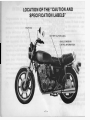
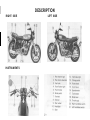
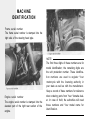
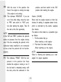
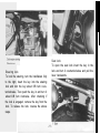
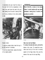
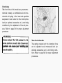
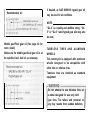
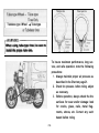
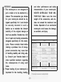
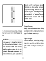
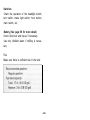
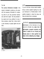
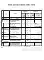
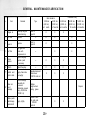
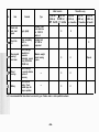
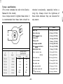
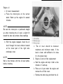
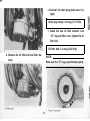
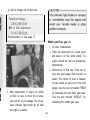
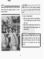
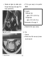
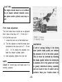
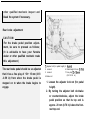
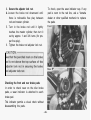
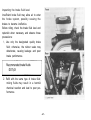
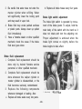
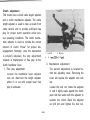
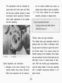
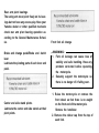
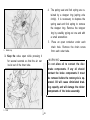
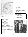
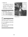
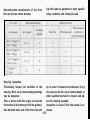
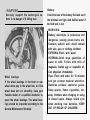
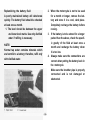
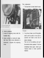
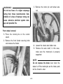
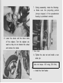
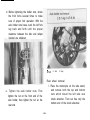
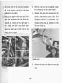
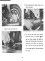
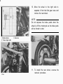
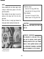
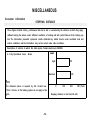
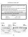
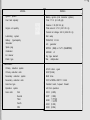
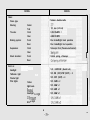
XS850G OWNER’S MANUAL
1ST PRINTING, JULY 1979
ALL RIGHTS RESERVED,
BY YAMAHA MOTOR COMPANY
LIMITED, JAPAN
PRINTED IN JAPAN
P/N LIT-l 1626-01-79
PLEASE READ THIS MANUAL CAREFULLY AND COMPLETELY
BEFORE OPERATING THIS MOTORCYCLE.
DO NOT ATTEMPT TO OPERATE THIS MOTORCYCLE UNTIL
YOU HAVE ATTAINED A SATISFACTORY KNOWLEDGE OF ITS
CONTROLS AND OPERATING FEATURES AND HAVE BEEN
TRAINED IN SAFE AND PROPER RIDING TECHNIQUES.
REGULAR INSPECTIONS AND CAREFUL MAINTENANCE ARE
REQUIRED IN ADDITION TO RIDING SKILL IN ORDER TO
ENJOY THE CAPABILITIES AND RELIABILITY OF THIS MOTORCYCLE SAFELY.
Particularly important information is distinguished in this manual by the following notations:
NOTE:
A NOTE provides key information to make procedures
easier or clearer.
CAUTION:
A CAUTION indicates special procedures that must be followed to avoid damage to the motorcycle.
W A R N I N G : A WARNING indicates special procedures that must be followed to avoid injury to a motorcycle operator or person inspecting or repairing the motorcycle.
NOTE:
This manual should be considered a permanent part of this motorcycle and
should remain with it even if the motorcycle is subsequently sold.
-SAFETY WARNINGS:
1, Traffic regulations vary from state to state. Study the regulations
in your state before riding this motorcycle.
2. This motorcycle is designed for on-road use only. It is not suitable for off-road use.
3. GASOLINE IS HIGHLY FLAMMABLE:
* Always turn off the engine when refuelling.
* Take care not to spill any gasoline on the engine or exhaust
pipe(s)/muffler(s) when refuelling.
* Never refuel while smoking or in the vicinity of an open flame.
4. If you should swallow some gasoline, or inhale a lot of gasoline
vapor, or allow some gasoline to get in your eye(s), see your
doctor immediately. If any gasoline spills on your skin or clothing, immediately wash it with soap and water and change your
clothes.
5. Always turn off the engine before leaving the motorcycle unattended and do not forget to remove the ignition key. When parking the motorcycle, note the following:
* The engine and exhaust pipe(s)/muffler(s) may be hot. Park the
motorcycle in a place where pedestrians or children are not likely to touch the motorcycle.
* Do not park the motorcycle on a slope or soft ground; the motorcycle may overturn.
6. When transporting the motorcycle in another vehicle, be sure it
is kept upright and that the fuel petcock(s) is turned to the “ON”
or “RES” position (for vacuum type)/“OFF” position (for manual
type). If it should lean over, gasoline may leak out of the carbretor or fuel tank.
7. Never start your engine or let it run for any length of time in a
closed area. The exhaust fumes are poisonous and may cause
loss of consciousness and death within a short time. Always
operate your motorcycle in en area with adequate ventilation.
6. Always wear a helmet, gloves, trousers (tapered around the cuff
and ankle so they do not flap), and a brightly colored jacket.
INTRODUCTION
Congratulations on your purchase of the
Yamaha XS850G. This model represents the
product of many years of Yamaha experience
in the production of fine sporting. touring,
and pacesetting racing machines. You can
now appreciate the high degree of craftsmanship and reliability that have made
Yamaha a leader in these fields.
This manual will provide the owner with a
good basic understanding of the operation
and basic maintenance of this vehicle. If you
have any questions regarding the operation
or maintenance of your motorcycle. please
consult your Yamaha dealer.
-NOTICE:
Some data in this manual may become
outdated due to improvements made to
this model in the future. If there is any
question concerning this manual, consult your nearby Yamaha dealer.
This Yamaha Motorcycle in its design and
manufacture fully complies with the emissions standards for clean air applicable at
the date of manufacture. Yamaha has met
these standards without reducing the
motorcycle’s performance or economy of
operation. To maintain these high standards.
it is important that you and your dealer pay
close attention to the
recommended
maintenance schedules and operating instructions contained within this manual.
SERVICE DEPT.
INTERNATIONAL DIVISION
YAMAHA MOTOR CO., LTD.
CONTENTS
LOCATION OF THE “CAUTION AND
SPECIFICATION LABELS” ,.,.,....................... 1
DESCRIPTION ..,,,...........................................~ 2
MACHINE I D E N T I F I C A T I O N 3
CONTROL F U N C T I O N S 4
PRE-OPERATION CHECKS ..,,...................... 15
OPERATION AND IMPORTANT
RIDING POINTS
24
PERIODIC MAINTENANCE AND
MINOR REPAIR .,.......,,,,,,.,..,.,.,...................... 30
CLEANING AND STORAGE .,....................... 72
MISCELLANEOUS
75
SPECIFICATIONS
77
WARRANTY INFORMATION
80
MAINTENANCE RECORD
81
WIRING DIAGRAM
83
DESCRIPTION
RIGHT SIDE
INSTRUMENTS
LEFT SIDE
MACHINE
IDENTIFICATION
Frame serial number
The frame serial number is stamped into the
right side of the steering head pipe.
Engine serial number
The engine serial number is stamped into the
elevated part of the right rear section of the
engine.
NOTE:
The first three digits of these numbers are for
model identification; the remaining digits are
the unit production number. These identification numbers are used to register Your
motorcycle with the licensing authority in
your state as well as with the manufacturer.
Keep a record of these numbers for reference
when ordering parts from Your Yamaha dealer. In case of theft, the authorities will need
these numbers and Your model name for
identification.
ON:
With the lever in this position fuel
flows if the engine is running but stops
if the engine is not running.
RES: This indicates “RESERVE”. If you run
out of fuel while riding, move the lever
to “PRI” and switch to “RES” position after starting the engine. Then, fill
the tank at the first opportunity.
NOTE:
In the “ON” and “RES” positions the petcock
works on pressure from the engine turning
over. If the line connecting the petcock to the
carburetor intake manifold is not connected
or has a leak the petcock will not function
properly.
PRI: This indicates “PRIME”. With the fuel
petcock in this position fuel flows
whether the engine is running or not. If
the fuel tank is completely empty, refill
the tank, prime the carburetor in this
position, and then switch to the “ON”
position after starting the engine.
Starter (CHOKE)
When cold, the engine requires a richer fuel
mixture for starting. A separate starter circuit,
which is controlled by the starter, supplies
this mixture.
The starter on this model is a 2-position type
as follows:
1. Pull the starter fully up.
-When starting a cold engine.
2. Push back the starter half-way.
-When warming up the engine.
NOTE:
Refer to “Starting and warming up a cold
engine” for proper operation.
Steering lock
To lock the steering, turn the handlebars fully
to the right, insert the key into the steering
lock and turn the key about l/8 turn counterclockwise. Then push the key in and turn it
about l/8 turn clockwise. After checking if
the lock is engaged, remove the key from the
lock. To release the lock. reverse the above
steps.
Seat lock
To open the seat lock insert the key in the
lock and turn it counterclockwise and pull the
lever backwards.
In reinstalling the seat. insert the lobes on
the seat front into the receptacles on the
frame, then push down the seat at the end.
After making sure the seat is securely fitted,
turn the key clockwise to the center position
to lock.
Never ride with a helmet in the helmet
holder. It could interfere with rear wheel
movement, causing loss of control and
possibly an accident.
Side cover (Left and Right)
To remove the right side cover, pull out the
bottom of the cover. To reinstall the cover.
make sure the top of the cover is securely
seated on the hinge hooks, then push the
bottom of the cover into its snap fitting.
Helmet holder
To open the helmet holder. insert the key in
the lock and turn it clockwise.
To lock the helmet holder, replace the holder
in the original position.
-12-
Front forks
The front forks of this model are pneumomechanical; namely, a combination air and mechanical coil spring in the inner tube provides
suspension best suited to the motorcycle’s
load (ex: optional accessories etc.) and riding
conditions by the adjustment of the air pressure. Refer to page 54 for proper adjustment
procedures.
Always adjust the fork preload to the
same position on each side. Uneven adjustment can cause poor handling and
::::::b::
-I3-
Rear shock absorber
The spring preload and the damping force
can be adjusted to suit motorcycle load (ex:
optional accessories etc.) and riding conditions. Refer to page 54 for proper adjustment
procedures.
Please ask your nearby Yamaha dealer for
further details.
Kick starter
To start the engine. rotate the kick crank.
push down lightly with foot until gears
engage, and then kick forcefully. This model
cannot be started unless the transmission is
in neutral.
An optional heavy duty rear shock absorber spring is available for this model.
* Heavy duty rear shock absorber
spring: P/No. 3J2-22212-A0
i
PRE-OPERATION CHECKS (DAILY)
Before using this motorcycle check the following points:
No.
Item
Routine
Page
Check operation, free play and fluid.
Top-up with DOT. #3 brake fluid
if necessary.
16.44
2. Clutch
Check operation. condition and free play.
Adjust if necessary.
17.49
3. Engine oil
Check engine oil level. add oil if necessary.
17.38
4
Check for leakage visually.
18.40
5. Throttle
Check for smooth operation.
Adjust if necessary.
17.50
6. Battery
Check fluid level. top-up with
distilled water if necessary.
23.58
7. Lights/Signals
Check operation.
22
8. Wheels/Tires
Check tire pressure. wear damage.
18
9. Fittings/Fasteners
Check all chassis fittings and fasteners.
Adjust. if necessary.
37
1.
Brakes (Front and Rear)
Middle/final Gear Oil
-15-
Pre-operation checks should be made each time the motorcycle is used. Such an inspection
can be accomplished in a very short time, and the added safety it assures is more than worth
the time involved.
. . . . .._.._ -.
1. The engine, exhaust pipe(s), and muffler(s) will be vary hot after the engine has
been run. Be careful not to touch them or to allow any clothing item to contact
them during inspection or repair.
2. If any item in the PRE-OPERATION CHECK is not working properly, have it inspected and repaired before operating the motorcycle.
-WARNING:
A soft, spongy feeling in the brake lever
(and/or brake pedal) indicates a failure
in the brake system. Do not operate the
motorcycle until the failure in the brake
system is corrected. Ask your Yamaha
dealer or other qualified mechanic for
immediate repairs. A soft, spongy feeling could indicate a hazardous condition
in the brake system.
Brakes (See page 44 for more detail)
1. Brake lever and brake pedal
Check for correct play in the front brake
lever and rear brake pedal. Make sure
they are working properly. Check the
brakes at low speed shortly after starting out.
-16-
leakage could indicate a hazardous condition in the brake system.
Clutch (See page 49 for more detail)
Check for correct play in the clutch lever and
make sure the lever operates properly.
If the play is incorrect, make an adjustment,
Throttle grip (See page 50 for more detail)
Turn the throttle grip to see if it operates
properly and if the play is normal. Make
certain the throttle springs closed when released.
Engine oil (See page 38 for more detail)
Make sure the engine oil is at the specified
level. Add oil as necessary.
I
1
Recommended oil:
Middle gear/Final gear oil (See page 40 for
more detail)
Make sure the middle gear/final gear oil is at
the specified level. Add oil as necessary.
I
If desired, an SAE 80W/90 hypoid gear oil
may be used for all conditions.
NOTE:
“GL-4” is a quality and additive rating. “GL5” or “GL-6” rated hypoid gear oils may also
be used.
TUBELESS TIRES AND ALUMINUM
WHEELS
This motorcycle is equipped with aluminum
wheels designed to be compatible with
either tube or tubeless tires.
Tubeless tires are installed as standard
equipment.
Do not attempt to use tubeless tires on
a wheel designed for use only with tubetype tires. Tire failure and personal injury may results from sudden deflation.
Tubeless-type Wheel --t Tube-type
When using tube-type tires be sure to
install the proper tube also.
rWARNING:To insure maximum performance, long service, and safe operation, note the following
precautions:
1. Always maintain proper air pressure as
described in the Chart on page 21.
2. Check tire pressure. before riding. adjust
as necessary.
3. Before operation, always check the tire
surfaces for wear and/or damage: look
for cracks, glass, nails, metal fragments, stones, etc. Correct any such
hazard before riding.
-19-
4. Always inspect the aluminum wheels
before a ride. Place the motorcycle on
the center stand and check for cracks,
bends or warpage of the wheels. If any
abnormal condition exists in a wheel,
consult your Yamaha dealer or other
qualified mechanic. Do not attempt
even small repairs to the wheel. If a
wheel is deformed or cracked, it must
be replaced.
5. Tires and wheels should be balanced
whenever either one is changed or replaced. Failure to have a wheel assembly balanced can result in poor performance, adverse handling characteristics,
and shortened tire life.
6. After installing a tire, ride conservatively
to allow the tire to seat itself on the rim
properly. Failure to allow proper seating
may cause tire failure resulting in
damage to the motorcycle and injury to
the rider.
7. After repairing or replacing a tire, check
to be sure the valve stem lock nut is
securely fastened. If not, torque it as
specified.
Tightening torque: 0.15 m-kg (1.1 ft-lb)
The standard equipment tires originally fitted
to the XS850G are suited to normal riding
and touring. They are not suited for sustained
high speed running or racing and must not be
used for such purposes. Consider your riding
skill, road and weather conditions, and correct weight distribution when loading your
motorcycle. Securely pack your heaviest
items close to the center of the motorcycle.
-WARNING:
1. This motorcycle is not designed to
pull a trailer or to be attached to a
sidecar. The accessories you choose
for your motorcycle should be designed specifically for it and should
be securely mounted in such a
fashion as to maintain the inherent
stability of the original design as
much as possible. Yamaha has a full
line of sport and touring accessories
designed specifically for this motorcycle. Please consider them before
making a purchase. Use of non-approved accessories may cause loss
of handling stability and riding safety. Consult your Yamaha dealer or
other qualified mechanic regarding
the consequences of using such
items.
2. Proper loading of your motorcycle is
important for the handling, braking,
I
and other performance and safety
characteristics of your motorcycle.
NEVER OVERLOAD YOUR MOTORCYCLE. Make sure the total
weight of the accessories, and etc.,
does not exceed the maximum load
limites. Operation of an overloaded
motorcycle could cause tire damage,
an accident, and injury.
should be left to a Yamaha Service
Technician or other qualified mechanic.
If you must change your own tire, be
sure to use proper tools and procedures
as described in the Tubeless Tire and
Wheel Manual available from Your
Yamaha dealer.
Fittings/Fasteners
Always check the tightness of chassis fittings
and fasteners before a ride. Use the chart on
page 37 to find the correct torque.
If a tire tread shows crosswise lines, it means
that the tire is worn to its limit. Replace the
tire.
Lights and signals
Check the headlight, flasher lights, taillight,
brake light, meter lights and all the indicator
lights to make sure they are in working condition.
-WARNING:
It is dangerous to ride with a worn-out
tire. When a tire tread begins to show
lines. Have Your Yamaha dealer or other
qualified mechanic replace the tire immediately. Brake pad replacement, tire,
and related wheel parts replacement
-22-
Switches
Check the operation of the headlight switch,
turn switch, brake light switch, horn button,
main switch, etc.
Battery (See page 58 for more detail)
Check fluid level and top-up if necessary.
Use only distilled water if refilling is necessary.
Fuel
Make sure there is sufficient fuel in the tank.
-23-
OPERATION AND
IMPORTANT RIDING
POINTS
-CAUTION:
I
1. Before riding this motorcycle, become thoroughly familiar with all
operating controls and their function. Consult your Yamaha dealer or
other qualified mechanic regarding
any control or function you do not
thoroughly understand.
2. Be careful where you store personal
items on the motorcycle. Avoid
blocking the air cleaner intake or
performance will suffer.
3. Be careful not to put anything near
the battery and its terminals. Electrical failure and acid corrosion may
result.
1.
Never start your engine or let it run
for any length of time in a closed
area. The exhaust fumes are poisonous and can cause loss of consciousness and death within a short time.
Always operate your motorcycle in
an area with adequate ventilation.
2. Before starting out, always be sure
the side stand is up. Failure to retract the side stand completely can
result in a serious accident when
you try to turn a corner.
Starting and warming up a cold engine
1. Shift transmission into neutral.
2. Turn the fuel petcock to “ON”.
3. Turn the ignition key to the “I” position
and the engine stop switch to “RUN”.
NOTE:
At this time the neutral indicator light (green)
and the oil pressure indicator light (red)
should be on. If the lights do not come on ask
your Yamaha dealer to inspect.
-I
The oil pressure indicator light should
go off after the engine is started.
If the indicator light flickers or remains
on, immediately stop the engine and
check the engine oil level and for oil
leakage.
If necessary, replenish oil, restart the
engine, and check to see that the oil
pressure indicator light goes off.
If the light does not go off even with
sufficient oil in the crankcase, consult
your Yamaha dealer or other qualified
mechanic.
4. Operate the starter (CHOKE) by pulling
up. Completely close the throttle grip.
5. Start the engine either by pushing the
starter button (or by using the kick
crank).
NOTE:
If the engine fails to start, release the starter
button, then push the starter button again.
Pause a few seconds before the next attempt.
Each cranking should be as short as possible
to preserve battery energy. Do not crank the
engine more than 10 seconds on each
attempt.
If the engine does not start with the starter
motor, use the kick starter to start the engine.
6. After starting the engine, push back
the starter half-way (warm-up position).
NOTE:
To get maximum engine life, always “warmup” the engine before starting off. Never
accelerate hard with a cold engine!
-25-
7. After warming up the engine, turn off
the starter (push back the starter completely).
Starting a warm engine
To start a warm engine, the starter (CHOKE)
is not required.
Engine break-in
There is never a more important period in
the life of your motorcycle than the period
between zero and 1,000 km (600 mi). For
this reason we ask that you carefully read the
following material. Because the engine is
brand new, you must not put an excessive
load on it for the first 1,000 km (600 mi).
The various parts in the engine wear and
polish themselves to the correct operating
clearances. During this period prolonged full
throttle operation, or any condition which
might result in excessive heating of the
engine, must be avoided.
-26-
0 ~ 150 km (0 ~ 90 mi):
Avoid operation above 4,000 r/min.
Allow a cooling off period of 5 to 10
minutes after every hour of operation.
Vary the speed of the motorcycle from
time to time. Do not operate it at one.
set throttle position.
150 ~ 500 km (90 ~ 300 mi):
Avoid prolonged operation above 5,000
r/min. A l l o w t h e m o t o r c y c l e t o r e v
freely through the gears but do not use
full throttle at any time.
500 ~ 1,000 km (300 ~ 600 mi):
Avoid prolonged full throttle operation.
Avoid cruising speeds in excess of
6,000 r/min.
1,000 km (600 mi) and beyond:
Avoid prolonged full throttle operation.
Avoid engine speeds in excess of 7,000
r/min. Vary speeds occasionally.
-CAUTION:
If any engine trouble should occur during the break-in period, consult your
Yamaha dealer immediately or other
qualified mechanic.
After 1,000 km (600 mi) of operation,
be sure to replace the engine oil, oil filter element, middle and final gear oil.
Shifting and acceleration
This model has a 5-speed transmission. The
transmission allows you to control the
amount of power you have available at a
given speed or while accelerating, climbing
hills, etc. The use of the change pedal is
shown in the illustration. (Page 8) 8)
To shift into NEUTRAL, repeatedly depress
the change pedal to the end of its travel (you
will feel a stop when you are in first gear).
then raise it slightly.
To start out and accelerate:
1 Pull the clutch lever to disengage the
clutch.
2 Shift into FIRST gear. The green neutral
indicator light should go out.
3 Open the throttle gradually. and at the
same time, release the clutch lever slowly.
At the recommended shift point speed in
the table below, close the throttle, and at
the same time, pull in the clutch lever
quickly.
5 Shift into SECOND gear. (Be careful not
to shift into neutral.)
6 Open the throttle part way and gradually
release the clutch lever.
7. To accelerate use the same procedure to
shift into the next higher gear according
to the Recommended Shift Point Chart
below.
4
-28-
To decelerate:
Apply front and/or rear brakes to slow
the motorcycle.
When the motorcycle reaches 20 km/h
(12.5 mi/h), shift to first gear.
Any time the engine appears about to
stall or runs very roughly, pull in the
clutch and use the brakes to stop.
When motorcycle is almost completely
stopped, shift to neutral.
The green neutral indicator light should
come on.
Recommended Shift Point
CAUTION:
1. Do not glide for long periods with
the engine off, and do not tow the
motorcycle a long distance. Even
with gears in neutral, the transmission is only properly lubricated when
the engine is running. Inadequate
lubrication may damage the transmission.
2. Always use the clutch when changing gears. The engine, transmission,
and driveline are not designed to
withstand the shock load of forced
shifting and can be damaged by
shifting without the clutch.
Parking
When parking, stop the engine and remove
the ignition key.
-WARNING:
Select a parking place where the motorcycle is not apt to fall. Do not park the
motorcycle on a slope or soft ground;
the motorcycle may overturn.
PERIODIC
MAINTENANCE AND
MINOR REPAIR
Periodic inspection, adjustment and lubrication will keep your motorcycle in the safest
and most efficient condition possible. Safety
is an obligation of the motorcycle owner.
The most important points of motorcycle inspection, adjustment and lubrication are explained in the following pages.
“Maintenance, replacement, or repair of
the emission control devices and systems
may be performed by any repair establishment or individual using any part which is
certified (if applicable).”
If the owner is not familiar with
done by a Yamaha dealer or other
qualified mechanic.
PERIODIC MAINTENANCE
PROPER PERIODIC MAINTENANCE OF
YOUR MOTORCYCLE IS IMPORTANT TO
ITS GIVING YOU LONG, PLEASURABLE
SERVICE: ESPECIALLY IMPORTANT ARE
THE MAINTENANCE SERVICES RELATED
TO EMISSIONS CONTROL. THESE CONTROLS NOT ONLY FUNCTION TO ENSURE
CLEANER AIR BUT ARE ALSO VITAL TO
ENGINE OPERATION AND
PROPER
MAXIMUM PERFORMANCE. IN THE FOLPERIODIC
TABLES OF
LOWING
MAINTENANCE, THE SERVICES RELATED
TO EMISSIONS CONTROL ARE GROUPED
SEPARATELY. THESE SERVICES REQUIRE
SPECIALIZED DATA, KNOWLEDGE, AND
EQUIPMENT. YAMAHA DEALERS ARE
TRAINED AND EQUIPPED TO PERFORM
THESE PARTICULAR SERVICES.
NOTE:
If you do not have a torque wrench available
during a service operation requiring one, take
your motorcycle to a Yamaha dealer or other
qualified mechanic to check the torque settings and adjust them as necessary.
Tool kit
The service information included in this
manual is intended to provide you, the owner.
with the necessary information for completing some of your own preventive maintenance and minor repairs. The tools provided in
the owner’s tool kit are sufficient for most of
these purposes. except that a torque wrench
is also necessary to properly tighten nuts and
bolts.
-WARNING:
Modifications to this motorcycle not approved by Yamaha may cause loss of
performance, excessive emissions can
render it unsafe for use. Consult your
Yamaha dealer or other qualified mechanic before attempting any changes.
-31-
PERIODIC MAINTENANCE EMISSION CONTROL SYSTEM
lnmal break-in
1*
Remarks
Item
No
I
Cam chain
I
Check and adjust chain tension,
0
I
Thereafter every
0
I
8,000 km
(5.000 ml)
or 12 months
4.000 km
(2.500 mi)
or 6 months
5,000 km
(3,000 ml)
or 7 months
1,000 km
(600 ml)
or 1 month
I
I
0
Check and adjust valve clearance
when engine IS cold.
0
Check condition. Adjust gap. Clean.
Replace after initial
1,300 km (8,000 mi).
0
4,x C r a n k c a s e
ventilation system
Check ventilation hose for cracks
or damage. Replace if necessary.
0
0
5*
Check fuel hose for cracks
or damage. Replace if necessary.
0
0
6* Exhaust system
Check for leakage.
Retighten as necessary.
Replace gasket(s) if necessary.
0
7+ C a r b u r e t o r
synchronization
Adjust synchronization of carburetors.
2* Valve clearance
3
Spark plugs
Fuel line
8* Idle speed
I
I
Check and adjust engine idle speed.
Adjust cable free play if necessary.
0
0
0
I
0
* It IS recommended that these items be serviced by your Yamaha dealer or other qualified mechanic
-32-
Replace.
Every 12,000 km or
18 months (7.500 mi).
0
0
0
I
Spark plug inspection
The spark plug is an important engine component and is easy to inspect. The condition
of the spark plug can indicate something of
the condition of the engine.
Normally, all spark plugs from the same
engine should have the same color on the
white porcelain insulator around the center
electrode. The ideal color at this point is a
medium to light tan color for a motorcycle
that is being ridden normally. If one spark
plug shows a distinctly different color, there
could be something wrong with the engine.
For example, a very white center electrode
porcelain color could indicate an intake tract
air leak or carburetion problem for that
cylinder. Do not attempt to diagnose such
problems yourself.
Instead. take the
motorcycle to your Yamaha dealer or other
qualified mechanic.
You should periodically remove and inspect
the spark plug because heat and deposits will
cause any spark plug to slowly break down
and erode. If electrode erosion becomes excessive, or if carbon and other deposits are
excessive, you should replace the spark plug
with one of the proper type.
7,
BP7ES (NGK) or N-7Y (CHAMPION)
Before installing any spark plug, measure the
electrode gap with a wire thickness gauge
and adjust to specifications.
-1
When installing the plug, always clean the
gasket surface and use a new gasket. Wipe
off any grime from the threads and torque the
spark plug properly.
NOTE:
If a torque wrench IS not available when you
are installing a spark plug. a good estimate of
the correct torque is l/4 to l/2 turns past
finger tights. Have the spark plug torqued to
the correct value as soon as possible with a
torque wrench.
-34
GENERAL MAINTENANCE/LUBRICATION
Thereafter every
lnitial break-In
No
Item
Remarks
1
Engine oil
Warm-up engine
before draining
2
O i l filter
Replace
Type
Refer to
page 38
Refer to
page 40
1,000 km
(600 mi)
or 1 month
5,000 km
(3.000 mi)
or 7 months
4,000 km
(2,500 mi)
or 6 months
0
0
0
0
0
0
3
Mrddlel/Frnal
gear oil
Replace
4
Air filter
Dry type filter
Clean with
compressed air
-
5 * Brake
system
Adjust free play
Replace pads
if necessary
-
0
0
0
6*
Adjust free play
-
0
0
0
Apply chain lube
thoroughly
Yamaha chain and
cable lube or
1 0W/30 motor oil
0
0
0
8*
Rear arm
pivot
bearings
Check bearings
assembly for
looseness.
Moderately repack
every 16,000 km
(10,000 ml)
Medium
weight wheel
bearing grease
9
Brake pedal
and change
pedal shaft
Apply lightly
Yamaha chain
and cable lube
or 10W/30
motor oil
Clutch
7* Control and
meter cable
8,000 km
16,000 km
(10,000 ml)
(5,000 ml)
or 12 months or 24 months
0
0
0
0
Repack
0
0
Initial break-in
No.
Remarks
Type
Center and
side stand
pivots
Apply lightly
Yamaha chain
and cable lube
or 1 0 W / 3 0
motor oil
Front fork
oil
Drain completely.
Refill to
specification
Yamaha fork
oil 10Wt or
equivalent
Steering ball
120 bearing
and races
Check bearings
assembly for
looseness.
Moderately repack
every 16,000 km
(10,000 mi)
Medium weight
wheel bearing
grease.
,3+ Wheel
bearings
Check bearings
for smooth rotation.
Replace if
necessary
I4
Check specific
gravity. Check
breather pipe for
proper operation
10
,,+
l
Item
Battery
Thereafter every
1,000 km
5,000 km
4.000 km
8,000 km
16.000 km
(600
mi)
or , month
K3.~~;~ths ( 2 . 5 0 0 mi)
(5.000 mi)
(10.000 mi)
or 6 months or 12 months or 24 month’
0
0
0
0
0
-
0
0
-
0
0
It is recommended that these items be serviced by your Yamaha dealer or other qualified mechanic.
-36-
Repack
Torque specifications
(For a more complete list, refer to the Service
Manual for this model.)
Use a torque wrench to tighten these items. It
is recommended that these items should be
t
5
i- 0B
0
checked occasionally, especially before a
long trip. Always check the tightness of
these items whenever they are loosened for
any reason.
Item
Spark plug
Engine drain plug
4.3 m-kg (31.0 ft-lb)
Middle
4.3 m-kg (31.0 ft-lb)
gear plug
Oil filter bolt
3.2 m-kg (23.0 ft-lb)
Change pedal
1.0 m-kg (7.0 ft-lb)
Front engine mount bolts
5.5 m-kg (40.0 ft-lb)
Rear
mount bolts
1.5 m-kg (11. 0 ft-lb)
Shock absorber (top)
3.0 m-kg (21.5 ft-lb)
Front wheel axle
4.5
1.5
11
3.0
22
5.5
40
8.5
13.0
94
-37-
3.9 m-kg (28.0 ft-lb)
10.5 m-kg (76.0 ft-lb)
Front axle holder
2.0 m - k g (14 .5 ft-lb)
Rear wheel axle
15.0 m - k g (108.5 ft-lb)
Rear axle pinch bolt
61
2.5 m-kg (18.0 ft-lb)
Steering pinch bolts
(bottom)
0.6
Torque
2.0 m-kg (14.5 ft-lb)
0.6 m-kg (4.5 ft-lb)
Front brake caliper bolt
2.5 m-kg (18 .0 ft-lb)
Final gear drain plug
2.3 m-kg (16.5 ft-lb)
Engine oil
1. Oil level measurement
a. Place the motorcycle on the center
stand. Warm up the engine for several
minutes.
NOTE:
Be sure the motorcycle is positioned straight
up when checking the oil level; a slight tilt
toward the side can produce false readings.
b. With the engine stopped, check the oil
level through the level window located
at the lower part of the right side
crankcase cover.
c. The oil level should be between
maximum and minimum marks. If the
level is lower. add sufficient oil to raise
it to the proper level.
2. Engine oil and oil filter replacement
a. Start the engine and stop it after a few
minutes of warm-up.
b. Place an oil pan under the engine and
remove the oil filler cover.
C. Remove the drain plug and drain the oil.
NOTE:
Wait a few minutes until the oil level settles
before checking.
-38-
e. Re-install the drain plug (make sure it is
tight).
Drain plug torque: 4.3 m-kg (31 .O ft-lb)
f. Install the new oil filter element. new
“O” ring and filter cover, tighten the oil
filter bolt.
Oil filter bolt: 3.2 m-kg (23.0 ft-lb)
d. Remove the oil filter bolt and filter element.
NOTE:
Make sure the "O" ring is positioned properly.
g. Add oil through the oil filler hole.
With oil filter replacement:
Recommended oil: See page 17.
I
I
h After replacement of engine oil, and/or
oil filter, be sure to check the oil pressure and for any oil leakage. The oil pressure indicator light should go off after
the engine is started.
Middle gear/Final gear oil
1. Oil level measurement
a. Place the motorcycle on a level place
and place it on the center stand. The
engine should be cool (at atmospheric
temperature).
b Remove the oil filler cap. Check the oil
level with level gauge (from tool kit) as
shown. The correct oil level is between
the two marks on each end of the level
gauge. Use the tool end marked “REAR”
for measuring the rear (final) gear case.
Use the end marked “MIDDLE” for
measuring the middle gear case.
NOTE:
Middle gear and final gear oil can be checked
with same level gauge, which is in the
owners tool kit.
Take care not to allow foreign material
2. Gear oil replacement
a. Place an oil pan under the transmission
for the middle gear and under the final
gear case.
b. Remove the middle and/or final gear oil
filler cap(s) and the drain plug(s), and
drain the oil.
-WARNING:
When draining or filling, take care not to
allow foreign material to enter the middle and/or final gear case. Do not allow
the gear oil to contact the tire and
wheel.
-41-
c. Reinstall and tighten the middle and/or
final gear drain plug(s). (See page 37 for
torque specifications.)
d. Fill the gear case(s) to the specified
Oil capacity:
Middle gear case:
Approx. 0.375 lit (0.40 US qt)
Final gear case:
Approx. 0.30 lit (0.32 US qt)
Recommended oil: See page 18.
e. Reinstall the filler cap(s) securely.
1
M,ddle gear drawn
plug
Air filter
1. Removal
a. Remove the air filter case cap by loosening the wing bolt.
2. Cleaning method
Tap the element lightly to remove most
of the dust and dirt; then blow out the
remaining dirt with compressed air from
the inner surface of the element. If element is damaged, replace it.
b. Pull out the element.
3. Reassemble by reversing the
procedure. Check whether the
is seated completely against the
4. The air filter element should be
at the specified intervals.
-43-
removal
element
case.
cleaned
-CAUTION:
The engine should never be run without
the air cleaner element installed; excessive piston and/or cylinder wear may result.
Front brake adjustment
The front brake lever should be so adjusted
that it has a free play of 5 ~ 8 mm (0.2 ~
0.3 in) at the lever end.
1. Loosen the lock nut on the brake lever.
2. Turn the adjuster so that the brake lever
movement at the lever end is 5 ~ 8 mm
(0.2 ~ 0.3 in) before the adjuster contacts the master cylinder piston.
3. After adjusting. tighten the lock nut.
NOTE:
Check for correct play and make sure it is
working properly.
-WARNING:
A soft or spongy feeling in the brake
lever (and/or brake pedal) can indicate
the presence of air in the brake system.
This air must be removed by bleeding
the brake system before the motorcycle
is operated. Air in the system will result
in greatly diminished braking capability
and can result in loss of control and an
accident. Have your Yamaha dealer or
other qualified mechanic inspect and
bleed the system if necessary.
Rear brake adjustment
-CAUTION:
For the brake pedal position adjustment, be sure to proceed as follows;
(It is advisable to have your Yamaha
dealer or other qualified mechanic make
this adjustment.)
I,
2.
3.
4.
The rear brake pedal should be so adjusted
that it has a free play of 13~ 15 mm (0.51
-0.59 in) from when the brake pedal is
stepped on to when the brake begins to
engage.
Adjuster bolt (for pedal height) 5. Footrest
6. Pedal height 20 mm 10.78 an,
Locknut
7. Free play 13- 15mm
Locknut
(0.51-0.59 in)
Brake rod
1. Loosen the adjuster lock nut (for pedal
height).
2. By turning the adjuster bolt clockwise
or counterclockwise, adjust the brake
pedal position so that its top end is
approx. 20 mm (0.78 in) below the footrest top end.
-45-
To check, open the wear indicator cap. If any
pad is worn to the red line, ask a Yamaha
dealer or other qualified mechanic to replace
the pads.
3. Secure the adjuster lock nut.
4. Loosen the brake rod downward until
there is noticeable free play between
rod and master cylinder.
5. Turn in the brake rod until it lightly
touches the master cylinder, then turn it
out by approx. 1 and 3/4 turns (for proper free play).
6. Tighten the brake rod adjuster lock nut.
Checking the front and rear brake pads
In order to check wear on the disc brake
pads, a wear indicator is attached to each
brake pad.
This indicator permits a visual check without
disassembling the pads.
-46-
Inspecting the brake fluid level
Insufficient brake fluid may allow air to enter
the ‘brake system, possibly causing the
brakes to become ineffective.
Before riding, check the brake fluid level and
replenish when necessary. and observe these
precautions:
1, Use only the designated quality brake
fluid; otherwise, the rubber seals may
deteriorate, causing leakage and poor
brake performance.
II
2. Refill with the same type of brake fluid;
mixing fluids may result in a harmful
chemical reaction and lead to poor performance.
-47-
Be careful that water does not enter the
master cylinder when refilling. Water
will significantly lower the boiling point
and may result in vapor lock.
4. Brake fluid may erode painted surfaces
or plastic parts. Always clean up spilled
fluid immediately.
5. Have a Yamaha dealer or other qualified
mechanic check the cause if the brake
fluid level goes down.
b. Replace all brake hoses every four years.
3.
Brake light switch adjustment
The brake light switch is operated by movement of the brake pedal. To adjust, hold the
main body of the switch with the hand so it
does not rotate and turn the adjusting nut.
Proper adjustment is achieved when the
brake light comes on slightly before the
brake begins to take effect.
Brake fluid replacement
1. Complete fluid replacement should be
done only by trained Yamaha service
personnel or other qualified mechanic.
2. Complete fluid replacement should be
done whenever the caliper cylinder or
master cylinder is disassembled, or the
fluid becomes seriously contaminated.
3. R e p l a c e t h e f o l l o w i n g c o m p o n e n t s
whenever damaged or leaking. Also:
a Replace all brake seals every two years.
1. Main body
-48-
2
Ad,“stlng
nut
,
Clutch adjustment
This model has a clutch cable length adjuster
and a clutch mechanism adjuster. The cable
length adjuster is used to take up slack from
cable stretch and to provide sufficient free
play for proper clutch operation under various operating conditions. The clutch mechanism adjuster is used to provide the correct
amount of clutch “throw” for proper disengagement, Normally, once the mechanism
is properly adjusted, the only adjustment
required is maintenance of free play at the
clutch handlebar lever.
1. Free play adjustment
Loosen the handlebar lever adjuster
lock nut, Next turn the length adjuster
either in or out until proper lever free
play is achieved.
1. Locknut
2. Adjuster
a. 2- 3 mmlO08- 0.12 Ill)
2. Mechanism adjustment
The second adjustment is located behind the adjusting cover. Removing the
cover will expose the adjuster and lock
nut.
Loosen the lock nut, rotate the adjuster
in until it lightly seats against the clutch
push rod that works with the adjuster to
operate the clutch. Back the adjuster
out l/4 turn and tighten the lock nut.
-49-
This adjustment must be checked because heat and clutch wear will affect
this free play, possibly enough to cause
incomplete clutch operation. Recheck
clutch cable adjustment at the handlebar after adjusting.
Cable inspection and lubrication
1. Damage to the outer housing of the
various cables may cause corrosion.
Often free movement will be obstruct-
ed. An unsafe condition may result, S O
replace such cables as soon as possible.
2. If the inner cables do not operate
smoothly, lubricate or replace them.
Throttle cable and grip lubrication
The throttle twist grip assembly should be
greased when the cable is lubricated, since
the grip must be removed to get at the end of
the throttle cable. Two screws clamp the
throttle housing to the handlebar. Once these
two are removed, the end of the cable can be
held high to pour in several drops of lubricant. With the throttle grip disassembled,
coat the metal surface of the grip assembly
with a suitable all-purpose grease to cut
down friction.
Rear arm pivot bearings
The swing arm must pivot freely on its bearings but not have any excess play. Have your
Yamaha dealer or other qualified mechanic
check rear arm pivot bearing operation according to the General Maintenance Schedule.
Front fork oil change
,--WARNING:
1. Fork oil leakage can cause loss of
stability and safe handling. Have any
problem corrected before operating
the motorcycle.
2. Securely support the motorcycle so
there is no danger of it falling over.
Brake and change pedal/Brake and clutch
lever
Lubricate the pivoting parts of each lever and
pedal.
1. Raise the motorcycle or remove the
front wheel so that there is no weight
on the front end of the motorcycle.
Remove the handlebar.
2. Remove the rubber cap from the top of
each fork.
Center and side stand pivots
Lubricate the center and side stands at their
pivot points.
-51-
4. The spring seat and fork spring are retained by a stopper ring (spring wire
circlip). It is necessary to depress the
spring seat and fork spring to remove
the stopper ring. Remove the stopper
ring by carefully prying out one end with
a small screwdriver.
5. Place an open container under each
drain hole. Remove the drain screw
from each outer tube.
1. Rubbercap
3. Keep the valve open while pressing it
for several seconds so that the air can
be let out of the inner tube.
-WARNING:
Do not allow oil to contact the disc
brake components. If any oil should
contact the brake components it must
be removed before the motorcycle is operated. Oil will cause diminished braking capacity and will damage the rubber
components of the brake assembly.
I-
1. Push
-52-
6. When most of the oil has drained,
slowly raise and lower the outer tubes
to pump out the remaining oil.
7. Inspect the drain screw gasket. Replace
if damaged. Reinstall the drain screw.
8. Pour the specified amount of oil into the
fork inner tube.
Front fork oil (each fork):
195 cc (6.60 oz)
Yamaha Fork Oil 10 wt or equivalent
9. After filling. slowly pump the forks up
and down to distribute the oil.
10. Inspect the “O-ring” on the spring seat.
Replace “O-ring” if damaged.
11.
Reinstall the spring seat and fill the fork
with air using a manual air pump or
other pressurized air supply. Refer to
“Front fork and rear shock absorber adjustment” for proper air pressure adjusting.
NOTE:
When checking and adjusting the air pressure, there should be no weight on the front
end of the motorcycle.
2. Remove the rubber cap from the top of
each fork.
3. Using the air gauge, check and adjust
the air pressure.
If the air pressure is increased, the
suspension becomes stiffer and if decreased, it becomes softer.
To increase:
Use a manual air pump or other pressurized air supply.
To decrease:
Release the air by pushing the valve pin.
Maximum air pressure:
2.5 kg/cm* (36 psi)
Do not exceed this amount
Front fork and rear shock absorber adjustment
Front fork:
1. Elevate the front wheel by placing the
motorcycle on the center stand.
-54-
4. Install the rubber caps securely.
Rear shock absorber:
1, Spring preload
If the spring seat is raised, the spring
becomes stiffer and if lowered, it becomes softer.
Standard position - A
A. position - Softest
E. position - Stiffest
Standard air pressure:
0.4 kg/cm* (5.7 psi)
Maximum air pressure:
2.5 kg/cm’ (36 psi)
Minimum air pressure: Zero
* Never exceed the maximum pressure,
or oil seal damage may occur.
* The difference between both the left
and right tubes should be 0.1 kg/cm’
(1.4 psi) or less.
-55-
2. Damping force
Turn the damping force adjuster with
your fingers to increase or decrease the
damping force. If it is difficult to turn it
with your fingers. use a screw driver.
NOTE:
When adjusting the damping force, the adjuster should be placed in the clicked position. If not. the damping force will be set to
the maximum (No. 4).
Always adjust both the right and left absorbers to the same position.
-56-
Recommended combinations of the front
fork and the rear shock absorber.
Steering inspection
Periodically inspect the condition of the
steering. Worn out or loose steering bearings
may be dangerous.
Place a block under the engine to raise the
front wheel of the motorcycle off the ground:
then hold the lower end of the front fork and
Use this table as guidance to meet specific
riding conditions and motorcycle load.
try to move it forward and backward. If any
free play can be felt, ask a Yamaha dealer or
other qualified mechanic to inspect and adjust the steering assembly.
Inspection is easier if the front wheel is removed.
-57-
Securely support the motorcycle so
there is no danger of it falling over.
Wheel bearings
If the wheel bearings in the front or rear
wheel allow play in the wheel hub, or if the
wheel does not turn smoothly, have your
Yamaha dealer or a qualified mechanic inspect the wheel bearings. The wheel bearings should be inspected according to the
General Maintenance Schedule.
Battery
Check the level of the battery fluid and see if
the terminals are tight. Add distilled water if
the fluid level is low.
-WARNING:
Battery electrolyte is poisonous and
dangerous, causing severe burns, etc.
Contains sulfuric acid. Avoid contact
with skin, eyes or clothing. Antidote:
EXTERNAL-Flush with water.
INTERNAL-Drink large quantities of
water or milk. Follow with milk of
magnesia, beaten egg or vegetable oil.
Call physician immediately.
Eyes: Flush with water for 15 minutes
and get prompt medical attention.
Batteries produce explosive gases.
Keep sparks, flame, cigarettes, etc.
away. Ventilate when charging or using
in closed space. Always shield eyes
when working near batteries. KEEP
OUT OF REACH OF CHILDREN.
Replenishing the battery fluid
A poorly maintained battery will deteriorate
quickly. The battery fluid should be checked
at least once a month.
1. The level should be between the upper
and lower level marks. Use only distilled
water if refilling is necessary.
NOTE:
Normal tap water contains minerals which
are harmful to a battery; therefore, refill only
with distilled water.
2. When the motorcycle is not to be used
for a month or longer, remove the battery and store it in a cool, dark place.
Completely recharge the battery before
reusing.
3. If the battery is to be stored for a longer
period than the above, check the specific gravity of the fluid at least once a
month and recharge the battery when
it is too low.
4. Always make sure the connections are
correct when putting the battery back in
the motorcycle.
Make sure the breather pipe is properly
connected and is not damaged or
obstructed.
Headlight
This motorcycle is equipped with a quartz
bulb headlight. If the headlight bulb burns
out. replace the bulb as follows:
1. Headlight bulb replacement
a. Remove the 2 screws holding the light
unit assembly to the headlight body.
c. Turn the bulb holder counterclockwise
and remove the defective bulb.
b. Disconnect the lead wires and remove
the light unit assembly.
d. Slip a new bulb into position and secure
it with the bulb holder
-CAUTION:
1. Avoid touching the glass part of the
bulb. Also keep it free from oil
stains; otherwise, the transparency
of the glass, life of the bulb and illuminous flux will be adversely affected. If the glass is oil stained.
throughly clean it with a cloth moistened with alcohol or lacquer thinner.
2. Keep flammable products or your
hands away from the bulb while it is
on. because it hearts up. Do not
touch the bulb until it cools down.
e
Reinstall the light unit assembly to the
headlight body. Adjust the headlight
beam if necessary.
2. Headlight beam adjustment
a Horizontal adjustment:
To adjust the beam to the right, turn the
adjusting screw clockwise.
To adjust the beam to the left. turn the
screw counterclockwise.
Fuse replacement
1. The fuse block is located under the seat.
b. Vertical adjustment:
1 ) Loosen the adjusting screw under the
headlight body.
2) Adjust vertically by moving the headlight body. When proper adjustment is
determined, retighten the adjusting
screw.
2.
If any fuse is blown, turn off the ignition
switch and the switch in the circuit in
question and install a new fuse of
proper amperage.
Then turn on the switches, and see if
the electrical device operates. If the fuse
immediately blows again, consult your
Yamaha dealer or other qualified
mechanic.
3. Remove the cotter pin and wheel axle
nut.
-WARNING:
Do not use fuses of a higher amperage
rating than those recommended. Substitution of a fuse of improper rating can
cause extensive electrical system damage and possible fire.
Front wheel removal
1. Place the motorcycle on the center
stand.
2. Remove the front fender securing bolts
and remove the fender.
4. Loosen the wheel axle holder nuts.
5. Remove the axle shaft, In this case,
make sure the motorcycle is properly
supported.
NOTE:
Do not depress the brake lever when the
wheel is off the motorcycle as the brake pads
will be forced to shut.
-63-
7. During reassembly, check the following:
a. Make sure the projecting portion
(torque stopper) of the speedometer
housing is positioned correctly.
6. Lower the wheel until the discs come
off the calipers. Turn the calipers outward so they do not obstruct the wheel
and remove the wheel.
1. Torque stopper
b. Tighten the axle nut and install a new
cotter pin.
Axle nut torque: 10.5 m-kg (76.0 ft-lb)
c. Install the front fender.
-64-
d. Before tightening the holder nuts, stroke
the front forks several times to make
sure of proper fork operation. With the
axle holder nuts loose, work the left fork
leg back and forth until the proper
clearance between the disc and caliper
bracket are obtained.
1
1st
2. 2nd
3 Gap
Rear wheel removal
1. Place the motorcycle on the side stand,
and remove both the top and bottom
nuts which mount the left side rear
shock absorber. Then set free only the
bottom end of the shock absorber.
e. Tighten the axle holder nuts. First
tighten the nut on the front end of the
axle holder, then tighten the nut on the
rear end.
-65-
4. With the wire tool in this position, place
the motorcycle on the center stand.
5. Remove the seat and unscrew the rear
fender installation bolts until their
threaded portion is completely out.
Reinsert those bolts as stoppers to hold
the rear fender up.
Hook one end of the wire tool (contained in the owner’s tool kit) to the hook
attached to the frame.
Apply your weight to the rear part of the
seat, and compress the rear shock absorbers by pulling up the right side of
the swing arm with your hand, then
hook the other end of wire tool to the
swing arm as shown.
1.
Installation bolts
6.
-66-
Remove the axle nut cotter pin and axle
nut.
8. While supporting the brake caliper, pull
out the rear axle.
7. Loosen the rear axle pinch bolt.
9.
-67-
Pull out the rear brake torque stopper
plate from where it is retained
the
rear arm. Next, suspend the caliper assembly with the big end of the wire tool
(contained in the owner’s tool kit) hanging on the rear stay and the small end
on the metal area of the brake caliper
hose joint.
10. Move the wheel to the right side to
separate it from the final gear case and
remove the rear wheel.
NOTE:
Do not depress the brake pedal when the
wheel is off the motorcycle as the brake pads
will be forced to shut.
1. Rubber retainer
2. Torque stopper plate
3. Rear arm
11. To install the rear wheel, reverse the
removal procedure.
1 Wire tool
-68-
NOTE:
Before installing the rear wheel, apply a light
coating of lithium base grease to the final
gear case splines.
When installing the rear wheel, be sure the
splines on the wheel hub fit into the final
gear case.
Make sure there is enough gap between the
brake pads before inserting the brake disc.
Tightening torque:
Axle nut: 15.0 m-kg (108.5 ft-lb)
Axle pinch bolt: 0.6 m-kg (4.0 ft-lb)
Shock absorber:
Top mount: 3.0 m-kg (21.5 ft-lb)
Bottom mount: 3.9 m-kg (28.0 ft-lb)
-CAUTION:
Always use a new cotter pin on the rear
axle nut.
-Carburetor adjustment:
The carburetor is a vital part of the engine and its emission control system.
Adjusting should be left to your Yamaha
dealer or other qualified mechanic with
the professional knowledge, specialized
data and equipment to do so properly.
1 Rear wheel hub splines
2. Final gear case splines
-69-
Troubleshooting
Although Yamaha motorcycles are given a
rigid inspection before shipment from the
factory, trouble may occur during operation.
If this happens, check the motorcycle in
accordance with the procedures given in the
following chart. If repair is necessary, ask a
qualified mechanic such as your Yamaha dealer for assistance. The skilled technicians at
your Yamaha dealer are trained and equipped to perform the necessary maintenance
and repair work. For replacement parts,
Yamaha recommends you use Genuine
Yamaha Parts, or parts you know are equivalent in quality.
Any problem in the fuel, compression or ignition system can cause poor starting, excessive emissions, engine damage, or loss of
power while riding. The troubleshooting
chart describes a quick and easy series of
system checks to locate the problem.
-70-
MISCELLANEOUS
Consumer information
STOPPING DISTANCE
These figures indicate braking
performance that can be met or exceeded by the vehicles to which they apply.
without locking the wheels. under different conditions of loading and with partial failures of the braking system The information presented represents results obtainable by skilled drivers under controlled road and
vehicle conditions and the information may not be correct under other conditions.
Description of vehicles to which this table apples. Yamaha motorcycle XS850G
A. Fully Operational Service
Load
Brake
178
Light
189
Maximum
IOTE:
‘he statement above is required
Partial
by U.S. Federal law.
0
100
200
300 (Feet)
failures of the braking system do not apply to this
Stopping distance in feet from 60 mi/h
hart.
-75-
ACCELERATION AND PASSING ABILITY
These figures indicate passing times and distances that can be met or exceeded by the vehicles to which they
apply in the situations diagrammed below.
The low-speed pass assumes an initial speed of 20 mi/h and a limiting speed of 35 mi/h. The high-speed
pass assumes an initial speed of 50 mi/h and a limiting speed of 80 mi/h.
NOTICE:
The information presented represents results obtainable by skilled
and vehicle
drivers under controlled road
conditions, and the information may not be correct under other conditions.
Description of vehicles to which this table applies
Yamaha motorcycle XS850G
Summary table
Low-speed p a s s . . . . . . . . . . . . . . . . . . . . . . . . . . . . . . . . . . . . . . 3 5 1 feet: 7.1 seconds
H i g h - s p e e d p a s s ,,.,,...................
LOW-SPEED
INITIAL
SPEED 20 mi/h
,...........
868 feet: 8.1 seconds
HIGH-SPEED
LIMITING
SPEED. 80 mi/h
INITIAL
SPEED 50 mi/h
TOTAL PASSlNG
TOTAL PASSlNG
DISTANCE. FEET
TIME SECONDS
CONSTANT 50 mi/h
contamination of wheel bearings, front
forks, brake calipers, and transmission
seals. Many expensive repair bills have
resulted from improper use of high pressure detergent applications such as
those available in coin-operated car
washes.
Once the majority of the dirt has been
hosed off, wash all surfaces with warm
water and mild, detergent type soap. An
old tooth brush or bottle brush is handy
to reach hard-to-get-to places.
Rinse motorcycle off immediately with
clean water and dry all surfaces with a
chamois, clean towel, or soft absorbent
cloth.
Chrome-plated parts such as handlebars, fenders, forks. etc., may be further
cleaned
with
automotive
chrome
cleaner.
Clean the seat with a vinyl upholstery
cleaner to keep the cover pliable and
glossy.
CLEANING AND
STORAGE
A. CLEANING
Frequent thorough cleaning of your motorcycle will not only enhance its appearance
but will improve general performance and
extend the useful life of many components.
1. Before cleaning the motorcycle:
a . Block off end of exhaust pipe to prevent
water entry: a plastic bag and strong
rubber band may be use.
b . Make sure spark plug and gas cap are
properly installed.
2. If engine case is excessively greasy.
apply degreaser with a paint brush. DO
not apply degreaser to wheel axles.
3. Rinse dirt and degreaser off with a
garden hose, using only enough hose
pressure to do the job. Excessive hose
pressure may cause water seepage and
-72-
8. Automotive-type wax may be applied to
all painted and chrome-plated surfaces.
Avoid
combination
cleaner-waxes.
Many contain abrasives which may mar
paint or protective finish on the fuel tank
and side covers.
9. After finishing, start the engine immediately and allow to idle for several
minutes.
B. STORAGE
Long term storage (60 days or more) of your
motorcycle will require some preventive
procedures to insure against deterioration.
After cleaning the machine thoroughly, prepare for storage as follows:
1. Drain fuel tank, fuel lines, and carburetor float bowl.
2. Remove empty fuel tank, pour a cup of
10 /30or 20W/40 motor oil in tank.
shake the tank to coat the inner surfaces thoroughly and drain off excess
the oil. Reinstall the tank.
3. Remove the spark plug. pour about one
t a b l e s p o o n o f 10W/30 o r 2 0 W / 4 0
motor oil in the spark plug hole and reinstall the spark plug. Kick the engine
over several times (with the ignition off)
to coat the cylinder walls with oil.
-WARNING:
When using starter motor to crank the
engine, remove spark plug wires and
ground them to prevent sparking.
4. Lubricate all control cables.
5. Block up the frame to raise both wheels
off the round.
6. Tie a plastic bag over the exhaust pipe
outlet to prevent moisture entering.
7. If storing in humid or salt-air atmosphere, coat all exposed metal surfaces
with a light film of oil. Do not apply oil
to any rubber parts or the seat cover.
8. Remove the battery and charge it. Store
it in a dry place and recharge it once a
month, Do not store the battery in an
excessively warm or cold place (less
than 0°C (32°F) or more than 30°C
(86°F)).
NOTE:
Make any necessary repairs before storing
the motorcycle.
-74-
SPECIFI CATIONS
General specifications
XS850G
MODEL
Dimension:
Overall length
2,175 mm (85.6 in)
Overall width
900 mm (35 .4 in)
Overall height
1,190 mm (46.9 in)
Wheelbase
1,450 mm (57.1
Mlnlmum road clearance
in)
140 mm /(5.5 in)
Weight:
241 kg (531 lb)
Net
Performance:
MInimum turning radius
2,400 mm (94.5 in)
Climbing capacity
26°
Engine:
Type
Engine model
4 stroke. gasoline. air-cooled, DOHC
Cylinder
3-cylinder in-line, Forward inclined
Displacment
Bore x stroke
826 cc (27.94 cu.in)
CompressIon ratio
9.2: 1
3J3
71.5 x 68.6 mm (2.815 x 2.701 in)
Electric and ckkick starter
Starting system
-77-
MODEL
Ignition
XS850G
system
Fuel tank capacity
Battery ignition (Full transistor ignition)
Total: 17 lit (4.5 US gal)
Engine oil quantity
Reserve: 3 lit (0.8 US gal)
Total amount: 3.7 lit (3.91 US qt)
Lubricating
Wet
Periodic oil change: 2.8 lit (2.96 US qt)
system
sump
Battery
type/capacity
Generator
YB14L/12V, 1 4 A H
Spark plug
BP7ES
Carburetor
HSC34-II
Air cleaner
Dry type element
Wet,
multiple-disc
A.C.
Clutch type
generator
(NGK) or N-7Y (CHAMPION)
x 3
Transmission:
Primary
reduction
system
Primary reduction ratio
HY-VO chain + gear
45/27 (1.666)
Secondary
reduction
system
Shaft drive
Secondary
reduction
ratio
35/31 x 19/18 x 32/11 = 3 . 4 6 6
Gear box type
Constant mesh, 5-speed
Operation
Left foot operation
Gear ratio:
system
First
32/14
(2.285)
Second
Third
27/l7
(1.588)
Fourth
23/21
(1.095)
Fifth
22/23
(0.956)
26/20
-78-
forward
MODEL
XS850G
I
Chassis:
Tubular. double-cradle
Frame type
Steering:
Caster
Trail
131 mm (5.16 in)
Tire size:
Front
3.25H 19-4PR
Rear
4.50H 17-4PR
Braking system:
Front
Disc brake/Right hand operation
Rear
Disc brake/Right foot operation
Telescopic fork (Pneumo-mechanical)
Suspension:
Front
Shock absorber:
Front
I
I
Rear
Coil/air spring, oil damper
Rear
Electrical:
Headlight
1 2V. 60W/55W (Quartz bulb)
Tail/brake light
12V. 8W
Flasher light
Pilot lights:
12V. 27W (32CP) x 4
(3CP)/27W (32CP)
Flasher
12V. 3.4W x 2
High beam
Neurl._^I
it,
12V. 3.4W x 1
x 2
12V. 3.4W x 1
Headlight outi w e
Oil p ,.udl”.l
ressure
12V. 3.4W x 1
M e t er light
L
*
-79-