1
OB405E.qxp
09.10.14 9:16 AM
Page 1
Revision E:
• SPECIFICATION has been modified.
Please void OB405 REVISED EDITION-D.
SPLIT-TYPE AIR CONDITIONERS
OUTDOOR UNIT
SERVICE MANUAL
No. OB405
REVISED EDITION-E
Models
MU-A18NDMU-A18NDMU-A24NDMU-A24NDMU-A30NDMU-A30ND-
S1
S2
S1
S2
S1
S2
Indoor unit service manual
MS-A• ND Series (OB404)
CONTENTS
MU-A18ND
1. TECHNICAL CHANGES ····································2
2. PART NAMES AND FUNCTIONS······················3
3. SPECIFICATION·················································3
4. OUTLINES AND DIMENSIONS ·························4
5. WIRING DIAGRAM ············································6
6. REFRIGERANT SYSTEM DIAGRAM ················8
7. PERFORMANCE CURVES ······························10
8. TROUBLESHOOTING······································12
9. DISASSEMBLY INSTRUCTIONS ····················21
10. PARTS LIST······················································27
11. RoHS PARTS LIST···········································30
NOTE:
• This service manual describes technical data of the outdoor units.
• RoHS compliant products have <G> mark on the spec name plate.
For servicing of RoHS compliant products, refer to the RoHS Parts List.
TM
OB405E.qxp
09.10.14 9:16 AM
Page 2
Revision A:
• Check of solenoid valve coil has been partially modified.
Revision B:
• MU-A24ND - S2
has been added.
Revision C:
• MU-A18ND - S2
has been added.
Revision D:
• MU-A30ND - S2
has been added.
Revision E:
• SPECIFICATION has been modified.
1
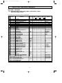
TECHNICAL CHANGES
w : change
Frequency
New Model
Old Model
Compressor: NH30VCD ➞ RH247NRAT
Compressor: RH277NHD ➞ RH247NRAT
Electricity receiving unit: Indoor unit ➞ Outdoor unit
Gas pipe diameter: [15.88 ➞ [12.7
Rated voltage: 220V ➞ 220-230V
60Hz
MU-A18ND - S1
MU-18TN - S1 MU-18SN w
w
w
w
w
w
w
w
Frequency
60Hz
New Model
MU-A24ND - S1
Old Model
MU-24TN - S1 MU-24SN Outdoor unit:Unit size:W850mmoH605mmoD290mm ➞ W840mmoH850mmoD330mm
w
Outdoor unit:Unit size:W870mmoH850mmoD295mm ➞ W840mmoH850mmoD330mm
w
Compressor: NH38NBD ➞ PH33NPBT
w
w
Electricity receiving unit: Indoor unit ➞ Outdoor unit
w
w
Liquid refrigerant pipe diameter: [9.52 ➞ [6.35
w
w
Rated voltage: 220V ➞ 220-230V
w
w
MU-A30ND - S1
New model
MU-A18ND - S1 ➔ MU-A18ND - S2
• Valve cover has been added.
MU-A24ND - S1 ➔ MU-A24ND - S2
• Compressor contactor has been added.
MU-A30ND - S1 ➔ MU-A30ND - S2
• Solenoid valve and solenoid valve coil have been changed.
2
C1
C2
09.10.14 9:16 AM
2
Page 3
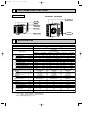
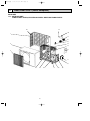
PART NAMES AND FUNCTIONS
OUTDOOR UNIT
MU-A18ND
MU-A24ND MU-A30ND
Air inlet
(back and side)
Air inlet
Piping
Drain hose
Air outlet
Air outlet
Drain outlet
3
SPECIFICATION
Outdoor model
MU-A24ND
MU-A18ND
Function
Fan
motor
Compressor
Electrical
data
Capacity
Capacity
kW
Dehumidification
R/h
Air flow (High/Low)
K /h
Power outlet
A
Running current (Total)
A
Power input (Total)
W
Power factor (Total)
%
Starting current (Total)
A
Compressor motor current
A
Fan motor current
A
Coefficient of performance (C.O.P) (Total)
Model
Output
W
Winding
"
resistance (at 20:)
Model
Winding
"
resistance (at 20:)
Dimensions WOHOD
mm
Weight
kg
Sound level (High/Low)
dB
Fan speed (High/Low)
rpm
Fan speed regulator
Refrigerant filling
kg
capacity (R22)
Refrigeration oil (Model)
cc
MU-A30ND
Cooling
Single phase
220-230V, 60Hz
Power supply
Special
remarks
OB405E.qxp
SSA 385
ISO 5151
4.40
5.10
1.8
2.3
2,480
15
9.94
8.52
2,100
1,800
96
96-92
40
9.02
7.60
0.55
2.10
2.83
RH247NRAT
1,200
C-R 1.43
C-S 2.06
RA6V60-MA
WHT-BLK 71.2
BLK-RED 89.3
850o605o290
44
54
945
1
ISO 5151
ISO 5151
SSA 385
SSA 385
8.1
6.6
6.6
5.9
4.3
3.2
3.2
2.7
2,880
2,880/1,380
25
15( S1 )
20( S2 )
14.25
10.54
17.52
12.42
3,010
2,250
3,700
2,650
96-92
97-93
96
97
58
78
13.22
9.50
16.49
11.39
0.66
0.66
2.69
1.78
2.93
2.23
PH33NPBT
NH44NAVT
1,500
2,000
C-R 0.84
C-R 0.62
C-S 2.09
C-S 1.40
RA6N75-BA
RA6N75-AA
WHT-BLK 65.0
WHT-BLK 64.2 BLK-YLW 32.9
BLK-RED 65.4
YLW-RED 32.7
840o850o330
67
76
54
55/51
790
790/490
1
2
1.40
2.20
2.40
520 (MS56)
900 (MS32N1)
1,300 (MS32N1)
NOTE: Test conditions are based on ISO 5151 / SSA 385
Cooling : Indoor
DB27°C WB19°C / DB29°C WB19°C
Outdoor DB35°C WB24°C / DB46°C WB24°C
Indoor-Outdoor piping length: 5 / 7.5 m
3
09.10.14 9:16 AM
4
Page 4
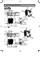
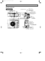
OUTLINES AND DIMENSIONS
REQUIRED SPACE
MU-A18ND - S1
OUTDOOR UNIT
355
350
Air in
Drainage
hole [16.2
20
100mm or more
OB405E.qxp
Unit: mm
ore
m
00m
or m
1
100
mm
or m
345
Air in
310
290
248
90
35
ore
re
Drainage
3holes [33
Air out
50
m
0m
50
30
or
mo
35
0m
m
Service panel
or
mo
re
20
50
100
157
292
3035-
605
Liquid refrigerant
pipe joint
Refrigerant pipe
(Flared) [6.35
183
Gas refrigerant
pipe joint
Refrigerant pipe
(flared) [12.7
161
500
850
74
MU-A18ND - S2
20
ore
rm
o
mm
100
100
mm
or m
ore
345
Air in
310
290
248
90
35
Drainage
hole [16.2
355
350
Air in
100mm or more
REQUIRED SPACE
re
Drainage
3holes [33
Air out
mm
or
mo
0
50
50
30
Service panel
20
50
100
157
292
3035-
605
Liquid refrigerant
pipe joint
Refrigerant pipe
(Flared) [6.35
183
500
850
161
74
81
4
Gas refrigerant
pipe joint
Refrigerant pipe
(flared) [12.7
35
0m
m
or
mo
re
09.10.14 9:16 AM
Page 5
MU-A24ND MU-A30ND
OUTDOOR UNIT
Open as a rule
500mm or more if
the front and both
sides are open
REQUIRED SPACE
515
299
40
100mm or more
200mm or more if
there are obstacles
to both sides
51
34
66
360
330
100mm or more
500
840
121
80
Open as a rule
500mm or more if the back,
both sides and top are open
350mm or more
30-
850
Service panel
155
90
35-
430
OB405E.qxp
198
5
Liquid refrigerant
pipe joint
Refrigerant pipe
(flared) [6.35(MU-A24ND)
[9.52(MU-A30ND)
Gas refrigerant
pipe joint
Refrigerant pipe
(flared) [15.88
Page 6
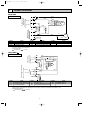
WIRING DIAGRAM
MU-A18ND
OUTDOOR UNIT
C2
RED
WHT
4 3 2 1
2
220-230V~
ORN
BLU
N
220-230V~
BLU
L
RED
ORANGE
WHITE
BLACK
MF
BRN
TB1
F
DSAR
POWER SUPPLY
220-230V ~/N 60Hz
TO INDOOR UNIT
CONNECTING
WHT
TB2
L
BLU
5
09.10.14 9:16 AM
BRN
OB405E.qxp
C
C1
BLU
N
RED
MC
S
GRN/YLW
BLK
NAME
SYMBOL
NAME
NAME
SYMBOL
SYMBOL
TERMINAL BLOCK
COMPRESSOR CAPACITOR
FUSE (3.15A)
C1
F
TB1
COMPRESSOR(INNER PROTECTOR)
TERMINAL BLOCK
OUTDOOR FAN CAPACITOR
C2
MC
TB2
OUTDOOR FAN MOTOR(INNER PROTECTOR)
DSAR SURGE ABSORBER
MF
NOTES: 1.About the indoor side electric wiring refer to the indoor unit electric wiring diagram for servicing.
2.Use copper conductors only (For field wiring).
3.Symbols below indicate.
: Connector
: Terminal block,
MU-A24ND- S1
L
TB1
BRN
BLU
220-230V~
RED
N
R
BLU 4 BLK
WHT 3 WHT
ORN
2
RED
1
C2
N
C
MF
ORN
RED
BLU
F
BLU
GRN/YLW
PE
S
MC
BLK
2 TB2
220-230V~
C1
WHT
L
DSAR BRN
TO INDOOR UNIT CONNECTING
POWER SUPPLY
~/N 220-230V 60Hz
OUTDOOR UNIT
NAME
SYMBOL
SYMBOL
NAME
NAME
SYMBOL
TERMINAL BLOCK
COMPRESSOR CAPACITOR
C1
F
TB1
FUSE(3.15A)
TERMINAL BLOCK
OUTDOOR FAN CAPACITOR
C2
MC
TB2
COMPRESSOR(INNER PROTECTOR)
DSAR SURGE ABSORBER
MF
OUTDOOR FAN MOTOR(INNER PROTECTOR)
NOTES: 1.Use copper conductors only (For field wiring).
2.Since the indoor and outdoor unit connecting wires have polarity, connect them according to the numbers (2,N,L).
3.Symbols below indicate.
: Terminal block,
: Connector
6
R
09.10.14 9:16 AM
Page 7
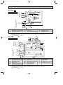
MU-A24ND- S2
BRN
TB1
1
BRN
52C
C1
BLU
N
4
S
RED
220-230V~
BLU
F
GRN/YLW
2
BLU
WHT
ORN
RED
TB2
3 WHT
MF
2 ORN
RED
C2
WHT
N
BLU
220-230V~
R
4 BLK
1
C
MC
BLK
PE
WHT
POWER SUPPLY
~/N 220-230V 60Hz
L
BLU
TO INDOOR UNIT CONNECTING
OUTDOOR UNIT
5
BRN
L
6
52C
DSAR
NAME
SYMBOL
SYMBOL
NAME
NAME
SYMBOL
TERMINAL BLOCK
COMPRESSOR CAPACITOR
C1
F
TB1
FUSE(3.15A)
TERMINAL BLOCK
OUTDOOR FAN CAPACITOR
C2
MC
TB2
COMPRESSOR(INNER PROTECTOR)
COMPRESSOR CONTACTOR
DSAR SURGE ABSORBER
MF
52C
OUTDOOR FAN MOTOR(INNER PROTECTOR)
NOTES: 1.Use copper conductors only (For field wiring).
2.Since the indoor and outdoor unit connecting wires have polarity, connect them according to the numbers (2,N,L).
3.Symbols below indicate.
: Terminal block,
: Connector
MU-A30ND
MF
LEV
6 5 4 3 2 1
L
CN662
YLW
BLK
WHT
RED
ORN
1 2 3 CN711
CN724
N
X63 X52
SR61
X63
COM NO
12V
21S2
NR61
COM NO
DEICER
T61
P.C. BOARD
3TB2
1
3
5
F61
CN730
RED
BLU
N
BRN
2
1
2
WHT
C
52C
C1
BLU
WHT
220-230V~
1
2
3
TAB52
X52
WHT
BLU
GRN/YLW
PE
C2
CN722
SR62
RED
S MC R
BLK
DSAR
POWER SUPPLY
SYMBOL
C1
C2
DSAR
F61
LEV
MC
MF
~/N 220-230V 60Hz
6
TB1
YLW
BLK
WHT
ORN
RED
RT62 RT63
OUTDOOR UNIT
TO INDOOR UNIT CONNECTING
OB405E.qxp
WHT
A1
BLU
52C
A2
BLU
NAME
SYMBOL
NAME
NAME
SYMBOL
COMPRESSOR CAPACITOR
TRANSFORMER
NR61
T61
VARISTOR
CONTACTOR
OUTDOOR FAN CAPACITOR
RT62
X52
DISCHARGE TEMPERATURE THERMISTOR
SOLENOID VALVE COIL RELAY
SURGE ABSORBER
RT63
X63
AMBIENT TEMPERATURE THERMISTOR
SOLENOID VALVE COIL
FUSE(3.15A)
SR61
21S2
SOLID STATE RELAY
COMPRESSOR CONTACTOR
EXPANSION VALVE COIL
SR62
52C
SOLID STATE RELAY
COMPRESSOR(INNER PROTECTOR)
TB1
TERMINAL BLOCK
OUTDOOR FAN MOTOR(INNER PROTECTOR)
TB2
TERMINAL BLOCK
NOTES: 1.Use copper conductors only (For field wiring).
2.Since the indoor and outdoor unit connecting wires have polarity, connect them according to the numbers (3,N,2).
3.Symbols below indicate.
: Terminal block,
: Connector
7
OB405E.qxp
6
09.10.14 9:16 AM
Page 8
REFRIGERANT SYSTEM DIAGRAM
MU-A18ND
Unit : mm
OUTDOOR UNIT
Refrigerant pipe
{12.7
(with heat insulator)
Stop Valve
(with service port)
Outdoor heat
exchanger
Compressor
Strainer
#100
Flared
connection
Capillary tube
[3.0 x [1.8 x 400
Stop Valve
Refrigerant pipe
{6.35
(with heat insulator)
MU-A24ND
OUTDOOR UNIT
Refrigerant pipe
[15.88
(with heat insulator)
Strainer
#100
Stop valve
(with service port)
Outdoor
heat
exchanger
Flared connection
Accumulator
Compressor
Flared connection
Stop valve
Refrigerant pipe
[6.35
(with heat insulator)
Capillary tube
[3.0 x [2.0 x 550
Refrigerant flow in cooling
8
OB405E.qxp
09.10.15 1:32 PM
Page 9
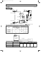
MU-A30ND
Unit : mm
OUTDOOR UNIT
Refrigerant pipe
[15.88
(with heat insulator)
Strainer
#100
Stop valve
(with service port)
Outdoor
heat
exchanger
Discharge
temperature
thermistor
RT62
Flared connection
Accumulator
Compressor
Capillary tube
[4.0 x [2.4 x 200
Solenoid valve
[4.2 x [3.0 x 50
Flared connection
LEV
(Expansion valve)
Stop valve
Refrigerant pipe
[9.52
(with heat insulator)
Ambient
temperature
thermistor
RT63
Capillary tube
[4.0 x [2.4 x 100
Strainer
#100
Capillary tube
[3.6 x [2.4 x 50
Refrigerant flow in cooling
MAX.REFRIGERANT PIPING LENGTH and MAX.HEIGHT DIFFERENCE
Piping size O.D : mm
Refrigerant piping : m
Model
Max. length Max. Height
A
difference
B
Gas
Liquid
{12.7
MU-A18ND
{6.35
MU-A24ND
30
15
{15.88
MU-A30ND
{9.52
Indoor
unit
Max. Height
difference
B
Max. length
A
Outdoor unit
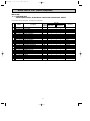
ADDITIONAL REFRIGERANT CHARGE(R22 : g)
Refrigerant piping length (one way)
Model
Outdoor unit precharged
MU-A18ND
1,400
MU-A24ND
2,200
MU-A30ND
2,400
7m
10m
15m
20m
30m
0
45
120
195
345
NOTE : Calculation : Xg=15g/m ✕ (Refrigerant piping length (m)-7)
9
OB405E.qxp
7
09.10.14 9:16 AM
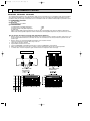
Page 10
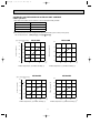
PERFORMANCE CURVES
MU-A18ND MU-A24ND MU-A30ND
The standard data contained in these specifications apply only to the operation of the air conditioner under normal conditions.
Since operating conditions vary according to the areas where these units are installed. The following information has been
provided to clarify the operating characteristics of the air conditioner under the conditions indicated by the performance curve.
(1) GUARANTEED VOLTAGE
198 ~ 253V, 60Hz
(2) AIR FLOW
Air flow should be set at MAX.
(3) MAIN READINGS
(1) Indoor intake air wet-bulb temperature :
°CWB
(2) Indoor outlet air wet-bulb temperature :
°CWB
(3) Outdoor intake air dry-bulb temperature :
°CDB
(4) Total input:
W
Indoor air wet/dry-bulb temperature difference on the left side of the following chart shows the difference between the
indoor intake air wet/dry-bulb temperature and the indoor outlet air wet/dry-bulb temperature for your reference at service.
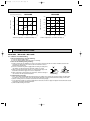
How to measure the indoor air wet/dry-bulb temperature difference
9.9
12.5 18.6
9.1
11.4 16.8
8.3
10.3 15.1
7.5
9.3 13.5
6.7
8.3 12.0
5.9
7.3 10.5
MS-A30ND
MU-A30ND
3.
4.
5.
6.
7.
MS-A24ND
MU-A24ND
2.
Attach at least 2 sets of wet and-dry-bulb thermometers to the indoor air intake as shown in the figure, and at least 2 sets
of wet-and-dry-bulb thermometers to the indoor air outlet. The thermometers must be attached to the position where air
speed is high.
Attach at least 2 sets of wet and dry-bulb thermometers to the outdoor air intake.
Cover the thermometers to prevent direct rays of the sun.
Check that the air filter is cleaned.
Open windows and doors of the room.
Press the EMERGENCY OPERATION switch once to start the EMERGENCY COOL MODE.
When system stabilizes after more than 15 minutes, measure temperature and take an average temperature.
10 minutes later, measure temperature again and check that the temperature does not change.
MS-A18ND
MU-A18ND
1.
INDOOR UNIT
OUTDOOR UNIT
Wet and dry-bulb
thermometers
Wet-and dry-bulb
thermometers
Indoor intake air WB temperature (:)
Indoor intake air WB temperature (:)
Outdoor intake air DB temperature (:)
Outdoor intake air DB temperature (:)
10
09.10.14 9:16 AM
Page 11
OUTDOOR LOW PRESSURE AND OUTDOOR UNIT CURRENT
COOL operation
① Both indoor and outdoor units are under the same temperature/humidity condition.
Dry-bulb temperature (:)
Relative humidity (%)
20
50
25
60
30
70
➁ Air flow should be set at MAX.
3 The unit of pressure has been changed to MPa on the international system of units(SI unit system).
f [Gauge])
The conversion factor is : 1(MPa [Gauge]) =10.2(kgf/f
8.0
0.8
7.0
0.7
6.0
0.6
5.0
0.5
4.0
0.4
3.0
0.3
15
MU-A18ND
MU-A18ND
8.0
Outdoor unit current (A)
Outdoor low pressure
(kgf/F [Gauge])(MPa [Gauge])
18 20
50
30 32
70
25
(kgf/F [Gauge])(MPa [Gauge])
7.0
6.0
5.0
4.0
15
35 (:)
(%)
Ambient temperature (˚C)/Ambient humidity (%)
0.8
10.0
7.0
0.7
9.0
6.0
0.6
4.0
3.0
25
60
30 32
70
35(:)
(%)
MU-A24ND
MU-A24ND
8.0
5.0
18 20
50
Ambient temperature (˚C)/Ambient humidity (%)
Outdoor unit current (A)
Outdoor low pressure
OB405E.qxp
0.5
0.4
8.0
7.0
6.0
0.3
5.0
15
18 20
50
25
60
30 32
70
35(:)
(%)
Ambient temperature (˚C)/Ambient humidity (%)
15
18 20
50
25
60
30 32
70
35(:)
(%)
Ambient temperature (˚C)/Ambient humidity (%)
11
OB405E.qxp
09.10.14 9:16 AM
6.0
0.6
5.0
0.5
4.0
0.4
3.0
0.3
MU-A30ND
MU-A30ND
15.0
Outdoor unit current(A)
Outdoor low pressure
(kgf/F[Gauge])(MPa[Gauge])
Page 12
14.0
13.0
12.0
11.0
10.0
0.2
15
2.0
18 20
50
25
60
30 32
70
9.0
15
35(:)
(%)
Ambient temperature (˚C)/Ambient humidity (%)
8
18 20
50
25
60
30 32
70
35(:)
(%)
Ambient temperature (˚C)/Ambient humidity (%)
TROUBLESHOOTING
MU-A18ND
MU-A24ND MU-A30ND
8-1. Cautions on troubleshooting
1. Before troubleshooting, check the following:
1) Check the power supply voltage.
2) Check the indoor/outdoor connecting wire for mis-wiring.
2. Take care the following during servicing.
1) Before servicing the air conditioner, be sure to turn off the main unit first with the remote controller, and then after
confirming the horizontal vane is closed, turn off the breaker and / or
disconnect the power plug.
2) Be sure to turn OFF the power supply before removing the front panel,
the cabinet, the top panel and the electronic control P.C. board.
3) When removing the electronic control P.C. board, hold the edge of the
board with care NOT to apply stress on the components.
4) When connecting or disconnecting the connectors, hold the housing of
Housing point
Lead wiring
the connector. DO NOT pull the lead wires.
3. Troubleshooting procedure
1) First, check if the OPERATION INDICATOR lamp on the indoor unit is flashing on and off to indicate an abnormality.
To make sure, check how many times the abnormality indication is flashing on and off before starting service work.
2) Before servicing that the connector and terminal are connected properly.
3) If the electronic control P.C. board is supposed to be defective, check the copper foil pattern for disconnection and the
components for bursting and discolouration.
4) When troubleshooting, refer to 8-2.
12
OB405E.qxp
09.10.14 9:16 AM
Page 13
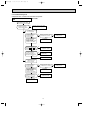
8-2. Instruction of troubleshooting
Start
Indoor unit
operates.
Outdoor unit
dose not
operate.
Outdoor unit
operates in
only Test Run
operation. w
Check room
temperature
thermistor.
Refer to
"Test point
diagram and
voltage".
MU-A30ND
Outdoor unit
dose not
operate
even in
Test Run
operation. w
Refer to
8-4. A
"Check of
outdoor unit".
MS-A30ND
Flash on and
off at 0.5-second
intervals
Cause:
Indoor/
Outdoor unit
• Mis-wiring
2-time flash
Cause:
Indoor unit
• Trouble of
room temperature/
indoor coil
thermistor
Refer to
8-4. C
"How to
check
mis-wiring
(When
outdoor unit
dose not
work)" .
Check room
temperature
thermistor
and indoor
coil thermistor.
Refer to
"Test point
diagram and
voltage".
w
Indoor unit
operates.
Outdoor unit
dose not operate
normally.
MU-A24ND - S2
MU-A30ND
Outdoor unit
dose not
stop even
if indoor unit
stop.
Refer to
8-4. B
"Check of
outdoor unit".
3-time flash
Cause:
Indoor unit
• Trouble of
indoor fan
motor
Refer to
"Check of
indoor fan
motor".
Indoor unit
dose not receive
the signal from
remote controller.
MU-A30ND
Outdoor unit
repeats start
and stop.
Refer to
8-4. F
"Check of
solenoid
valve coil".
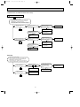
4-time flash
Cause:
Indoor unit
• Trouble of
indoor
control
system
Indoor unit
operates, when
EMERGENCY
OPERATION
switch is pressed.
Indoor unit
dose not operate,
when
EMERGENCY
OPERATION
switch is pressed.
Refer to
"Check of
remote controller
and receiver
P.C. board".
1. Check indoor /
outdoor
connecting wire.
2. Check of
outdoor fuse.
(MU-A18/A24ND)
3. Refer to
"Check of indoor
electronic control
P.C. board".
MU-A30ND
6-time flash
Cause:
Outdoor unit
• Trouble of
thermistor
in outdoor
unit
Refer to
8-4. E
"Check of
outdoor
thermistor".
Replace the
indoor
electronic
control
P.C. board.
OPERATION INDICATOR
lamp on the indoor unit is
flashing on and off.
MU-A30ND
7-time flash
Cause:
Outdoor unit
• Trouble of
outdoor
control
system
Replace the
deicer
P.C. board.
MU-A30ND
10-time flash
Cause:
Outdoor unit
• Trouble of
low discharge
temperature
protection
Refer to
8-4. D
"Check of
LEV".
Refer to indoor unit service manual.
"Test Run operation" means the operation within 30 minutes after EMERGENCY OPERATION switch is pressed.
13
OB405E.qxp
09.10.14 9:16 AM
Page 14
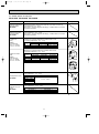
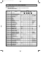
8-3. Trouble criterion of main parts
MU-A18ND MU-A24ND MU-A30ND
Part name
Discharge temperature
thermistor(RT62)
MU-A30ND
Check method and criterion
Figure
Measure the resistance with a tester.
Before measurement, hold the thermistor with your hands to warm it up.
(Part temperature 0˚C ~ 40˚C)
Refer to 8-5. "Test point diagram and voltage", "Outdoor deicer P.C. board",
the chart of thermistor.
Measure the resistance with a tester.
(Part temperature –10˚C ~ 40˚C)
Ambient temperature
thermistor(RT63)
MU-A30ND
Refer to 8-5. "Test point diagram and voltage", "Outdoor deicer P.C. board",
the chart of thermistor.
Compressor
(MC)
Measure the resistance between the terminals with a tester.
(Coil wiring temperature -10°C ~ 40°C)
INNER
PROTECTOR
155i 5: OPEN
90i10: CLOSE
Normal
Color of
lead wire MU-A18ND
MU-A24ND
MU-A30ND
C – R 1.26 " ~ 1.55 " 0.74 " ~ 0.91 " 0.54 " ~ 0.67 "
C – S 1.81 " ~ 2.23 " 1.84 " ~ 2.26 " 1.23 " ~ 1.52 "
WHT
C
P
S
R BLK
RED
Measure the resistance between the terminals with a tester.
(Coil wiring temperature -10°C ~ 40°C)
Outdoor fan motor
(MF)
INNER
PROTECTOR
135i 5: OPEN
87i15: CLOSE
Color of
lead wire
WHT – BLK
BLK – RED
BLK – YLW
YLW – RED
MU-A18ND
63 " ~ 77 "
79 " ~ 96 "
–
–
Normal
MU-A24ND
57 " ~ 70 "
58 " ~ 71 "
–
–
MU-A30ND
57 " ~ 69 "
–
29 " ~ 35 "
29 " ~ 35 "
MAIN
AUX.
BLK
RED ORN WHT
MU-A18/A24ND
MAIN
AUX.
BLK
YLW RED ORN WHT
MU-A30ND
Solenoid valve coil
(21S2)
MU-A30ND
Normal
37.4 " ~ 53.9 "
RED1
LEV
ORN4
BLU3
MU-A30ND
Color of lead wire
WHT – RED
RED – ORN
YLW – BRN
BRN – BLU
BRN2
LEV(Expansion valve)
WHT6
YLW5
Measure the resistance with a tester.
(Part temperature : 0˚C ~ 40˚C)
Measure the resistance with a tester.
(Part temperature : –10˚C ~ 40˚C)
Normal
MU-A30ND - S1
1,738 " ~ 2,125 "
MU-A30ND - S2
1,230 " ~ 1,330 "
P :INNER PROTECTOR
14
OB405E.qxp
09.10.14 9:16 AM
Page 15
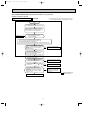
8-4. Troubleshooting flow
Compressor and / or outdoor fan motor dose not operate.
A Check of outdoor unit
MU-A30ND
Turn ON the power supply.
Is there 220-230V AC to
between L-N on the
outdoor terminal block?
No
Check the outdoor power supply
and connection of wiring.
Yes
Compressor
dose not operate.
Check the deicer P.C.
board. Refer to 8-5.
Is there 5V DC?
Yes
Press the EMERGENCY
OPERATION switch.
3-minute time delay works.
Test run operation
operates for 30 minutes.
Is there 220-230V AC
between A1 and A2 on the
compressor contactor (52C)?
No
Is there 220-230V AC CN730 No
on the deicer P.C. board?
Make the connection
of wiring correct.
Yes
Replace the
deicer P.C. board.
No
Replace the
deicer P.C. board.
No
Replace the compressor
contactor(52C).
Yes
Is there 220-230V AC between
2 on the compressor
contactor(52C) and N on
the outdoor terminal block?
Yes
Check the compressor.
Outdoor fan motor
dose not operate.
Check the deicer P.C.
board. Refer to 8-5.
Is there 5V DC?
Yes
Press the EMERGENCY
OPERATION switch.
3-minute time delay works.
Test run operation
operates for 30 minutes.
No
Is there 220-230V AC
CN711 1-3 or 2-3 on
the deicer P.C. board?
Yes
No
Is there 220V AC CN730
on the deicer P.C. board?
Yes
Replace the
deicer P.C. board.
Replace the
deicer P.C. board.
Check the outdoor fan
motor. Refer to 8-3.
15
No
Make the connection
of wiring correct.
OB405E.qxp
09.10.14 9:16 AM
Page 16
Compressor and / or outdoor fan motor dose not stop.
B Check of outdoor unit
MU-A24ND -
S2
1 Turn OFF the power supply.
2 After 30 seconds, turn ON the power supply again.
3 Operate the unit in COOL mode by pressing the
EMERGENCY OPERATION switch.
4 Operate the unit for 1 minute or more and stop it by
pressing the EMERGENCY OPERATION switch again.
After 30 seconds, does
compressor stop ?
No
Yes
Is there 220-230V AC
between 3-N on the outdoor
terminal block?
No
Yes
Is there 220-230V AC
between 1 on the compressor No
contactor(52C) and N on the
outdoor terminal block?
Make the connection
of wiring correct.
Yes
Replace the compressor
contactor(52C).
OK
Is there 220-230V AC
between 3-N on the indoor
terminal block?
Yes
No
Reconnect the continuity
of indoor and outdoor
unit connection.
Replace the indoor
electronic control P.C.
board.
After 30 seconds, does
outdoor fan motor stop ?
No
Yes
Is there 220-230V AC
between 3-N on the outdoor
terminal block?
No
Yes
Is there 220-230V AC
between 3 on the compressor No
contactor(52C) and N on the
outdoor terminal block?
Make the connection
of wiring correct.
Yes
OK
Replace the compressor
contactor(52C).
Is there 220-230V AC
between 3-N on the indoor
terminal block?
Yes
No
Reconnect the continuity
of indoor and outdoor
unit connection.
Replace the indoor
electronic control P.C.
board.
MU-A30ND
1 Turn OFF the power supply.
2 After 30 seconds, turn ON the power supply again.
3 Operate the unit in COOL mode by pressing the
EMERGENCY OPERATION switch.
4 Operate the unit for 1 minute or more and stop it by
pressing the EMERGENCY OPERATION switch again.
After 30 seconds,
did compressor stop?
No
Yes
Is there 220-230V AC
between A1 and A2 on the
compressor contactor (52C)?
Yes
Ok
Replace the
deicer P.C. board.
After 30 seconds,
did outdoor fan stop?
No
Replace the
deicer P.C. board.
Yes
Ok
16
No
Is there 220-230V AC between
2 on the compressor
contactor(52C) and N
on the outdoor terminal
block?
Yes
Replace the compressor
contactor(52C).
No
Make the connection
of wiring correct.
OB405E.qxp
09.10.14 9:16 AM
Page 17
When OPERATION INDICATOR lamp flashes ON and OFF in every 0.5-second.
Outdoor unit dose not operate.
C How to check mis-wiring
w Short circuit of JPG and JPS on the indoor electronic control
P.C. board enables self -check to be displayed in 3 seconds.
MU-A30ND
Start
• Turn ON the power supply.
• Press EMERGENCY OPERATION switch once.
When the unit has mis-wiring, in 3 minutes,
OPERATION INDICATOR lamp on indoor unit
flash on and off at 0.5 second intervals. w
Yes
Make them sure.
Is this mis-wiring, poor contact,
or wire disconnection?
No
1. Turn OFF the power supply and disconnect only terminal
block 3 of indoor/ outdoor connecting wire on indoor side.
2. Short-circuit terminal block N-3 by lead wire.
3. Turn ON the power supply and press EMERGENCY OPERATION switch once.
Is there 1V DC detected between both ends
of PS132 on the indoor electronic control P.C.
board ?
However, the stylus of a tester would be
between 0 and 20V.
Yes
No
Replace the indoor electronic
control P.C. board.
• Turn OFF the power supply.
• Disconnect the lead wire that terminal
block N-3 is short-circuited.
• Connect ON indoor/outdoor connecting wire.
Turn ON the power supply.
No
Is there 220-230V AC between L-N
on the outdoor terminal block?
Check the outdoor power supply
and connection of wiring.
Yes
No
Is there 5V DC between J101 + -J401 - ?
(Refer to 8-5.)
Yes
When EMERGENCY OPERATION
is operated, is there 10V DC between both
ends of R601 on the deicer P.C. board?
(Refer to 8-5.)
However the stylus of a tester would be
between 5 ~10V.
Yes
No
Replace the deicer P.C. board.
Make the wiring between CN730
on the deicer P.C. board and
outdoor terminal block correct.
(Refer to 8-5.)
Refer to indoor unit
service manual.
Replace the deicer P.C. board.
17
OB405E.qxp
09.10.14 9:16 AM
Page 18
When OPERATION INDICATOR lamp flashes 10-time.
Cooling mode dose not operate.
D Check of LEV (Expansion valve)
Remote controller model : KP0B
Turn ON the power supply.
1 While pressing OPERATION
SELECT button on the remote
controller, press RESET button.
2 Release RESET button to confirm
if all LCD in operation display
section of the remote controller is
displayed.
3 Release OPERATION SELECT
button.
MU-A30ND
Remote controller model : KM04B
Turn ON the power supply.
1 While pressing both OPERATION
SELECT button and TOO COOL
button on the remote controller at the
same time, press RESET button.
2 First, release RESET button.
And release the other two buttons
after all LCD in operation display
section of the remote controller is
displayed after 3 seconds.
KP0B
KM04B
With remote controller set toward the indoor unit, press
OPERATE/ STOP(ON/ OFF) button and confirm one beep tone.
LEV operates in full-opening
direction.
˚C
˚C
CLOCK
CLOCK
AMPM
AMPM
AMPM
Do you hear the expansion valve
"click, click·······"?
Do you feel the expansion valve
vibrate on touching it?
No
Is LEV properly fixed to
the expansion valve?
AMPM
Yes
Ok
No
Properly fix LEV coil to
the expansion valve.
Yes
Does the resistance of LEV
have the characteristics
on 8-3?
Yes
Replace the
deicer P.C. board.
NOTE : After check of LEV, do the undermentioned operation.
No
1. Turn OFF the power supply and turn ON again.
2. Press the RESET button on the remote controller.
Replace the LEV.
When OPERATION INDICATOR lamp flashes 6-time.
Thermistors in the outdoor unit are abnormal.
E Check of outdoor thermistor
MU-A30ND
w Disconnect the connectors CN662 from the deicer P.C. board. (Check the characteristics of each thermistor.)
Discharge temperature
thermistor(RT62)
Measure
resistance
between CN 662
1 and 2.
Turn OFF the
power supply.
Ambient temperature
thermistor(RT63)
Replace the deicer P.C.
board.
Does the
resistances of
thermistor have
the characteristics
on 8-5.?
No
Measure
resistance
between CN 662
3 and 4.
Replace the
thermistor.
Yes
Connect CN662.
Turn ON the power
supply and press
the EMERGENCY
OPERATION
switch.
No
Does the unit operate
10 minutes or more?
Yes
Ok W
W Defective contact of the connector is considered.
18
OB405E.qxp
09.10.14 9:16 AM
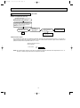
Page 19
F Check of solenoid valve coil
MU-A30ND
Outdoor unit repeats start and stop.
Turn ON the power supply.
Operate the unit in COOL mode by pressing
the EMERGENCY OPERATION switch.
After 1minute or more has passed since the
compressor started, operate the solenoid valve coil
by heating or cooling the ambient temperature
thermistor.
(Refer to Solenoid valve control.)
Do you hear "click" from the
solenoid valve coil?
Yes
No
Turn ON the
solenoid valve coil.
(Refer to Solenoid
valve control.)
Ok
Is there 220-230V AC
CN722 on the deicer
P.C. board?
Yes
Check of the
solenoid valve coil.
(Refer to 8-3.)
No
Replace the
deicer P.C. board.
Solenoid valve control
The solenoid valve opens when the ambient temperature thermistor RT63 temperature reaches 49.2: or more after 1
minute has passed since the compressor turned on. Then, the solenoid valve maintains to open until the ambient temperature thermistor RT63 temperature falls 46.2: or less.
Ambient temperature thermistor
RT63 temperature
Solenoid valve
ON
OFF
46.2:49.2:
NOTE: The solenoid valve remains to close when the ambient temperature thermistor RT63 temperature is 49.2: or
less after 1 minute has passed since the compressor turned on.
19
OB405E.qxp
09.10.14 9:16 AM
Page 20
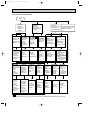
8-5. Test point diagram and voltage
MU-A30ND
Outdoor deicer P.C. board
Ambient temperature thermistor (RT63)
100
Discharge temperature thermistor(RT62)
900
Resistance(k")
800
700
600
Resistance(k")
90
80
70
60
50
40
500
400
30
300
20
200
10
100
0
0 10 20 30 40 50 60 70 80 90 100 110 120
Temperature(:)
CN662 1-2
Discharge temperature
thermistor (RT62)
(Refer to 8-4.E.)
0
-20 -10 0 10 20 30 40
Temperature(:)
CN662 3-4
Ambient temperature thermistor
(RT63)
(Refer to 8-4.E.)
LEV
connector
(CN724)
Fan motor
connector Varistor
(CN711)
(NR62)
Solenoid
valve coil
(CN722)
+
} 12V DC
Fuse
3.15A / 250V
J101 +
5V
DC
J401
(Refer to
8-4. C.)
}
Varistor (NR61)
CN7301-3
220-230-240V
AC
}
(Refer to
8-4. A or C.)
+
}
R601
10V DC
20
(Refer to
8-4. C.)
OB405E.qxp
09.10.14 9:16 AM
9
Page 21
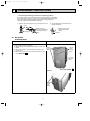
DISASSEMBLY INSTRUCTIONS
<"Terminal with locking mechanism" Detaching points>
The terminal which has the locking mechanism can be detached as shown below.
There are two types ( Refer to (1) and (2)) of the terminal with locking mechanism.
The terminal without locking mechanism can be detached by pulling it out.
Check the shape of the terminal before detaching.
(1) Slide the sleeve and check if there is a locking lever or not.
(2) The terminal with this connector has the
locking mechanism.
Sleeve
Locking lever
1Slide the sleeve.
2Pull the terminal while
pushing the locking
lever.
1Hold the sleeve, and
pull out the terminal
slowly.
Connector
9-1. MU-A18ND
OUTDOOR UNIT
OPERATING PROCEDURE
PHOTOS
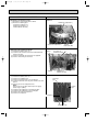
1. Removing the cabinet
(1) Remove the screws of the cabinet.
(2) Hold the bottom of the cabinet on both sides to remove the
cabinet.
(3) Remove the screws of the service panel and remove the
service panel.
(4) Remove the screw of the valve cover and remove the valve
cover (MU-A18ND- S2 ).
Photo 1
Screws
of the
cabinet
Screws
of the
Service
panel
Screw of
the valve
cover
Photo : MU-A18ND Photo 2
Screws
of the
cabinet
21
S2
OB405E.qxp
09.10.14 9:16 AM
Page 22
PHOTOS
OPERATING PROCEDURE
2. Removing the electrical parts
Photo 3
(1) Remove the service panel and the cabinet.
(2) Remove the following parts.
•Compressor capacitor (C1)
•Outdoor fan capacitor (C2)
•Terminal blocks (TB1,TB2)
Outdoor fan capacitor(C2)
Compressor capacitor(C1)
Photo 4
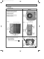
3. Removing the outdoor fan motor
(1) Remove the cabinet. (Refer to 1.)
(2) Disconnect the connector remove the hooked lead wire
from the fan motor.
(3) Remove the propeller nut and remove the propeller.
(4) Remove screws fixing the fan motor.
Hook
Set screws of
outdoor fan motor
Propeller
nut
Propeller
(5)
(6)
(7)
(8)
(9)
Set screws of
Outdoor fan motor
Photo 5
4. Removing the compressor
(1)
(2)
(3)
(4)
Terminal
blocks(TB1,TB2)
Remove the cabinet. (Refer to 1.)
Remove the soundproof felt.
Remove the terminal cover on the compressor.
Disconnect lead wires from the glass terminal of the compressor.
Recover gas from the refrigerant circuit.
NOTE:
Recover gas from the pipes until the pressure gauge
shows 0 kg/cm2 (0MPa).
Disconnect the welded part of the discharge pipe.
Disconnect the welded part of the suction pipe.
Remove nuts fixing the compressor.
Remove the compressor.
Discharge
pipe
Suction
pipe
Compressor
Compressor nuts
22
OB405E.qxp
09.10.14 9:16 AM
Page 23
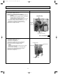
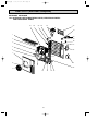
9-2. MU-A24ND
OUTDOOR UNIT
OPERATING PROCEDURE
PHOTOS
1.Removing the cabinet
Photo 1
(1) Remove the screw of the service panel.
(2) Remove the screws of the top panel.
(3) Remove the screw of the valve cover.
(4) Remove the service panel.
(5) Remove the top panel.
(6) Remove the valve cover.
(7) Remove the screws of the front panel.
(8) Remove the front panel.
(9) Remove the screws of the back panel.
(10) Remove the back panel.
Photo 3
Screw of the top panel
Screws
of the
cabinet
Screws of the cabinet
Screw of the motor support
Photo 2
Screw of the service panel
Screws
of the
top
panel
Screws
of the
back
panel
Screws
of the
front
panel
Screw
of the
valve
cover
Set screws of the back panel
Photo 4
2. Removing the electrical parts
(1) Remove the service panel and the cabinet.
(2) Remove the following parts.
•Compressor capacitor (C1)
•Outdoor fan capacitor (C2)
•Terminal blocks (TB1,TB2)
•Compressor contactor (52C) (MU-A24ND-
Compressor
contactor
(MU-A24
ND- S2 )
S2
Screws of the relay panel
Terminal
blocks
(TB1,TB2)
)
Screws
of the
relay
panel
Compressor
capacitor (C1)
Outdoor fan
capacitor (C2)
Screws
of the
relay
panel
Photo : MU-A24ND 23
S2
OB405E.qxp
09.10.14 9:16 AM
Page 24
PHOTOS
OPERATING PROCEDURE
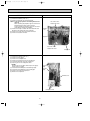
3. Removing the propeller and the outdoor fan motor
(1) Remove the cabinet. (Refer to 1.)
(2) Remove the propeller nut and the propeller.
NOTE : Loose the propeller in the rotating direction for
removal.
When attaching the propeller, align the mark on the
propeller and the motor shaft cut section.
Set the propeller in position by using the cut on the
shaft and the mark on the propeller.
(3) Remove the clamp of outdoor fan motor lead wire and
disconnect the outdoor fan motor connector.
(4) Remove the screws fixing the outdoor fan motor.
(5) Remove the outdoor fan motor.
Photo 5
Set screws of the
outdoor fan motor
Propeller
nut
Propeller
Set screws of
the outdoor fan motor
Photo : MU-A24ND 4. Removing the compressor
(1)
(2)
(3)
(4)
(5)
(6)
S2
Photo 6
Remove the cabinet. (Refer to 1.)
Remove the relay panel.
Remove the soundproof felt.
Remove the terminal cover on the compressor.
Disconnect lead wires from the compressor.
Recover gas from the refrigerant circuit.
Discharge pipe
Terminal cover
NOTE:
Recover gas from the pipes until the pressure gauge
shows 0 kg/cm2 (0 MPa).
(7) Disconnect the welded part of the discharge pipe.
(8) Disconnect the welded part of the suction pipe.
(9) Remove nuts fixing the compressor.
(10) Remove the compressor.
Suction pipe
Compressor nuts
24
OB405E.qxp
09.10.14 9:16 AM
Page 25
9-3. MU-A30ND
OUTDOOR UNIT
OPERATING PROCEDURE
PHOTOS
1.Removing the cabinet
Photo 1
(1) Remove the screw of the service panel.
(2) Remove the screws of the top panel.
(3) Remove the screw of the valve cover.
(4) Remove the service panel.
(5) Remove the top panel.
(6) Remove the valve cover.
(7) Remove the screws of the front panel.
(8) Remove the front panel.
(9) Remove the screws of the back panel.
(10) Remove the back panel.
Screw of the top panel
Screws
of the
cabinet
Screws of the cabinet
Photo 3
Photo 2
Screw of the motor support
Screw of the service panel
Screws
of the
top
panel
Screws
of the
back
panel
Screws
of the
front
panel
Screw
of the
valve
cover
Set screws of the back panel
2. Removing the deicer P.C. board
Photo 4
(1) Remove the service panel and the cabinet.
(2) Disconnect all the connectors and the terminals on the
deicer P.C. board.
(3) Remove the deicer P.C. board.
Screws
of the
relay
panel
Deicer P.C. board
Terminal blocks
(TB1,TB2)
Screws
of the
relay
panel
Compressor Compressor Outdoor fan
contactor
capacitor(C1) capacitor (C2)
(52C)
25
OB405E.qxp
09.10.14 9:16 AM
Page 26
PHOTOS
OPERATING PROCEDURE
3. Removing the propeller and the outdoor fan motor
(1) Remove the cabinet. (Refer to 1.)
(2) Remove the propeller nut and the propeller.
NOTE : Loose the propeller in the rotating direction for
removal.
When attaching the propeller, align the mark on the
propeller and the motor shaft cut section.
Set the propeller in position by using the cut on the
shaft and the mark on the propeller.
(3) Remove the clamp of outdoor fan motor lead wire and
disconnect the outdoor fan motor connector.
(4) Remove the screws fixing the outdoor fan motor.
(5) Remove the outdoor fan motor.
Photo 5
Set screws of the
outdoor fan motor
Propeller
nut
Propeller
Set screws of the
outdoor fan motor
Compressor
4. Removing the compressor
(1)
(2)
(3)
(4)
(5)
(6)
Photo 6
Remove the cabinet. (Refer to 1.)
Remove the relay panel.
Remove the soundproof felt.
Remove the terminal cover on the compressor.
Disconnect lead wires from the compressor.
Recover gas from the refrigerant circuit.
NOTE:
Discharge
pipe
Recover gas from the pipes until the pressure gauge
shows 0 kg/cm2 (0 MPa).
(7) Disconnect the welded part of the discharge pipe.
(8) Disconnect the welded part of the suction pipe.
(9) Remove nuts fixing the compressor.
(10) Remove the compressor.
Suction
pipe
Terminal cover
Compressor nuts
26
OB405E.qxp
09.10.14 9:16 AM
10
Page 27
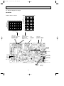
PARTS LIST (non-RoHS compliant)
MU-A18ND
10-1. OUTDOOR UNIT
STRUCTURAL PARTS, ELECTRICAL PARTS AND FUNCTIONAL PARTS
19
20
18
1
17
16
15
14
2
13
12
3
11
10
4
5
6
7
8
9
Part numbers that are circled are not shown in the illustration.
No.
1
2
3
4
5
6
7
8
9
10
11
12
13
14
15
16
17
18
19
20
21
22
23
Part No.
E02
E02
E02
E02
E02
E02
E02
E02
E02
E02
E02
E02
E02
E02
E02
E02
E02
E02
E02
E02
E02
E02
E02
E02
E02
E07
817
A27
817
817
141
496
075
949
817
A27
140
139
819
817
818
561
A27
890
795
798
895
816
817
627
A49
001
233
233
232
521
501
515
506
900
290
290
661
662
650
245
301
630
630
383
374
374
351
353
009
936
382
241
Part Name
BACK PANEL
BACK PANEL
CABINET
GRILLE
PROPELLER
MOTOR SUPPORT
COMPRESSOR RUBBER SET
COMPRESSOR
BASE
BASE
STOP VALVE(GAS)
STOP VALVE(LIQUID)
VALVE COVER
SERVICE PANEL
OUTDOOR FAN MOTOR
OUTDOOR HEAT EXCHANGER
OUTDOOR HEAT EXCHANGER
SURGE ABSORBER
TERMINAL BLOCK
TERMINAL BLOCK
OUTDOOR FAN CAPACITOR
COMPRESSOR CAPACITOR
HANDLE
CAPILLARY TUBE
FUSE
FUSE HOLDER
Q'ty/unit
Symbol
in Wiring
MU-A18ND - S1 MU-A18ND Diagram
1
1
1
1
1
1
1
1
1
1
3
3
1
1
MC
1
1
1
1
1
1
1
1
1
1
1
MF
1
1
1
1
DSAR
1
1
TB2
1
1
TB1
1
1
C2
1
1
C1
1
1
1
1
1
1
F
1
1
27
S2
Remarks
3RUBBERS/SET
RH247NRAT
{12.7
{ 6.35
RA6V60 -
3P
3P
3.0+/440V AC
35+/440V AC
{3.0o{1.8o400
3.15A
OB405E.qxp
09.10.14 9:16 AM
Page 28
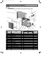
PARTS LIST (non-RoHS compliant)
MU-A24ND MU-A30ND
10-2. OUTDOOR UNIT STRUCTURAL PARTS, ELECTRICAL PARTS
AND FUNCTIONAL PARTS
27
26
25
24
22
23
A
21
B
1
20
19
2
18
3
17
4
16
5
7
17
15
8
6
14
9
10
28
11
12 13
OB405E.qxp
09.10.14 9:16 AM
Page 29
PARTS LIST (non-RoHS compliant)
MU-A24ND MU-A30ND
10-2. OUTDOOR UNIT STRUCTURAL PARTS, ELECTRICAL PARTS
AND FUNCTIONAL PARTS
Part numbers that are circled are not shown in the illustration.
No.
1
2
3
4
5
6
7
8
9
10
11
12
13
14
15
16
17
18
19
20
21
22
23
24
25
26
27
28
29
30
31
32
33
34
35
36
Part No.
E02
E02
E02
E02
E02
E02
E07
E02
E02
E02
E02
E02
E02
E02
E02
E02
E02
E02
E02
E02
E02
E02
E02
E02
E02
E02
E02
E02
E02
E02
E02
E02
E02
E02
E02
E02
E02
E02
E02
E02
E02
E02
E02
E02
E02
E02
E07
819
890
947
950
951
214
070
889
890
819
819
819
527
784
951
889
947
890
889
819
819
819
890
795
889
817
890
951
A19
951
889
816
819
817
726
890
819
A49
336
948
948
262
527
625
947
947
001
297
630
630
301
301
501
508
290
290
232
009
521
506
900
900
661
662
662
932
650
245
309
383
374
374
374
351
451
340
340
353
353
233
009
515
640
493
382
385
936
937
936
936
936
490
492
241
Part Name
TOP PANEL
OUTDOOR HEAT EXCHANGER
OUTDOOR HEAT EXCHANGER
OUTDOOR FAN MOTOR
OUTDOOR FAN MOTOR
PROPELLER
PROPELLER NUT
BASE
BASE
CABINET
HANDLE
FAN GUARD
COMPRESSOR RUBBER SET
COMPRESSOR
COMPRESSOR
STOP VALVE(GAS)
STOP VALVE(LIQUID)
STOP VALVE(LIQUID)
ACCUMULATOR
VALVE COVER
SERVICE PANEL
THERMISTOR
SURGE ABSORBER
TERMINAL BLOCK
TERMINAL BLOCK
TERMINAL BLOCK
OUTDOOR FAN CAPACITOR
DEICER P.C. BOARD
COMPRESSOR CONTACTOR
COMPRESSOR CONTACTOR
COMPRESSOR CAPACITOR
COMPRESSOR CAPACITOR
BACK PANEL(OUT)
HANDLE
MOTOR SUPPORT
EXPANSION VALVE
EXPANSION VALVE COIL
FUSE
VARISTOR
CAPILLARY TUBE(TAPER PIPE)
CAPILLARY TUBE(TAPER PIPE)
CAPILLARY TUBE
CAPILLARY TUBE
CAPILLARY TUBE
SOLENOID VALVE COIL
SOLENOID VALE
FUSE HOLDER
Symbol
in Wiring
MUDiagram A24ND -
MF
MF
MC
MC
RT62, RT63
DSAR
TB2
TB2
TB1
C2
52C
52C
C1
C1
LEV
F,F61
NR61
Q'ty/unit
S1
MUA24ND -
1
1
1
1
1
1
1
1
1
1
1
1
1
1
1
4
1
1
1
1
4
1
1
1
1
1
1
1
1
1
1
1
1
1
1
1
1
1
1
1
MUA30ND -
1
1
1
1
1
1
1
1
1
1
1
1
1
1
1
1
1
1
4
1
1
1
1
1
1
1
1
1
1
1
1
4RUBBERS/SET
PH33NPBT
NH44NAVT
{15.88
{6.35
{9.52
DISCHARGE, AMBIENT
3P
3P
3P
4.0+/440V AC
FIGUREB
FIGUREA
55+/440V AC
35+/440V AC
1
1
1
1
1
1
1
1
1
1
1
3.15A
1
1
RA6N75RA6N75-
1
1
1
1
1
Remarks
S1
1
1
1
21S2
29
S2
{4.2x{3.0x50
{3.6x{2.4x50
{4.0x{2.4x200
{4.0x{2.4x100
{3.0x{2.0x550
OB405E.qxp
11
09.10.14 9:16 AM
Page 30
RoHS PARTS LIST (RoHS compliant)
MU-A18ND
11-1. OUTDOOR UNIT
STRUCTURAL PARTS, ELECTRICAL PARTS AND FUNCTIONAL PARTS
19
20
18
1
17
16
15
14
2
13
12
3
11
10
4
5
30
6
7
8
9
09.10.14 9:16 AM
Page 31
RoHS PARTS LIST (RoHS compliant)
MU-A18ND
11-1. OUTDOOR UNIT
STRUCTURAL PARTS, ELECTRICAL PARTS AND FUNCTIONAL PARTS
Part numbers that are circled are not shown in the illustration.
No.
1
2
3
4
5
6
7
8
9
10
11
12
13
14
15
16
17
18
19
20
21
22
23
RoHS
OB405E.qxp
G
G
G
G
G
G
G
G
G
G
G
G
G
G
G
G
G
G
G
G
G
G
G
G
G
G
Part No.
E12
E12
E12
E12
E12
E12
E12
E12
E12
E12
E12
E12
E12
E12
E12
E12
E12
E12
E12
E12
E12
E12
E12
E12
E12
E17
817
A27
817
817
141
496
075
949
817
A27
140
139
819
817
818
561
A27
890
795
798
895
816
817
627
A49
001
233
233
232
521
501
515
506
900
290
290
661
662
650
245
301
630
630
383
374
374
351
353
009
936
382
241
Part Name
BACK PANEL
BACK PANEL
CABINET
GRILLE
PROPELLER
MOTOR SUPPORT
COMPRESSOR RUBBER SET
COMPRESSOR
BASE
BASE
STOP VALVE(GAS)
STOP VALVE(LIQUID)
VALVE COVER
SERVICE PANEL
OUTDOOR FAN MOTOR
OUTDOOR HEAT EXCHANGER
OUTDOOR HEAT EXCHANGER
SURGE ABSORBER
TERMINAL BLOCK
TERMINAL BLOCK
OUTDOOR FAN CAPACITOR
COMPRESSOR CAPACITOR
HANDLE
CAPILLARY TUBE
FUSE
FUSE HOLDER
Q'ty/unit
Symbol
in Wiring
MU-A18ND - S1 MU-A18ND Diagram
1
1
1
1
1
1
1
1
1
1
3
3
1
1
MC
1
1
1
1
1
1
1
1
1
1
1
MF
1
1
1
1
DSAR
1
1
TB2
1
1
TB1
1
1
C2
1
1
C1
1
1
1
1
1
1
F
1
1
31
S2
Remarks
3RUBBERS/SET
RH247NRAT
{12.7
{ 6.35
RA6V60 -
3P
3P
3.0+/440V AC
35+/440V AC
{3.0o{1.8o400
3.15A
OB405E.qxp
09.10.14 9:16 AM
Page 32
RoHS PARTS LIST (RoHS compliant)
MU-A24ND MU-A30ND
11-2. OUTDOOR UNIT STRUCTURAL PARTS, ELECTRICAL PARTS
AND FUNCTIONAL PARTS
27
26
25
24
22
23
A
21
B
1
20
19
2
18
3
17
4
16
5
7
17
15
8
6
14
9
10
32
11
12 13
09.10.14 9:16 AM
Page 33
RoHS PARTS LIST (RoHS compliant)
MU-A24ND MU-A30ND
11-2. OUTDOOR UNIT STRUCTURAL PARTS, ELECTRICAL PARTS
AND FUNCTIONAL PARTS
Part numbers that are circled are not shown in the illustration.
No.
RoHS
OB405E.qxp
1 G
G
2
G
G
3
G
4 G
5 G
G
6
G
7 G
8 G
9 G
10 G
G
11
G
12 G
G
13
G
14 G
15 G
16 G
17 G
18 G
G
19
G
20 G
21 G
G
22
G
G
23
G
G
24
G
25 G
26 G
27 G
28 G
29 G
30 G
31 G
G
32 G
G
G
33 G
G
G
34
G
G
35
G
36 G
Part No.
E12
E12
E12
E12
E12
E12
E17
E12
E12
E12
E12
E12
E12
E12
E12
E12
E12
E12
E12
E12
E12
E12
E12
E12
E12
E12
E12
E12
E12
E12
E12
E12
E12
E12
E12
E12
E12
E12
E12
E12
E12
E12
E12
E12
E12
E12
E12
E12
E12
E12
E17
819
890
947
950
951
214
070
889
890
819
819
819
527
784
951
889
947
890
889
819
819
819
890
795
889
817
890
951
B19
A19
951
889
816
819
817
726
890
819
A49
336
948
B18
948
262
527
625
947
B19
947
B18
001
297
630
630
301
301
501
508
290
290
232
009
521
506
900
900
661
662
662
932
650
245
309
383
374
374
374
351
451
451
340
340
353
353
233
009
515
640
493
382
385
936
936
937
936
936
936
490
490
492
492
241
Part Name
TOP PANEL
OUTDOOR HEAT EXCHANGER
OUTDOOR HEAT EXCHANGER
OUTDOOR FAN MOTOR
OUTDOOR FAN MOTOR
PROPELLER
PROPELLER NUT
BASE
BASE
CABINET
HANDLE
FAN GUARD
COMPRESSOR RUBBER SET
COMPRESSOR
COMPRESSOR
STOP VALVE (GAS)
STOP VALVE (LIQUID)
STOP VALVE (LIQUID)
ACCUMULATOR
VALVE COVER
SERVICE PANEL
THERMISTOR
SURGE ABSORBER
TERMINAL BLOCK
TERMINAL BLOCK
TERMINAL BLOCK
OUTDOOR FAN CAPACITOR
DEICER P.C. BOARD
DEICER P.C. BOARD
COMPRESSOR CONTACTOR
COMPRESSOR CONTACTOR
COMPRESSOR CAPACITOR
COMPRESSOR CAPACITOR
BACK PANEL (OUT)
HANDLE
MOTOR SUPPORT
EXPANSION VALVE
EXPANSION VALVE COIL
FUSE
VARISTOR
CAPILLARY TUBE (TAPER PIPE)
CAPILLARY TUBE (TAPER PIPE)
CAPILLARY TUBE (TAPER PIPE)
CAPILLARY TUBE
CAPILLARY TUBE
CAPILLARY TUBE
SOLENOID VALVE COIL
SOLENOID VALVE COIL
SOLENOID VALE
SOLENOID VALE
FUSE HOLDER
Q'ty/unit
Symbol
MUMUMUMUin Wiring
Diagram A24ND - A24ND - A30ND - A30ND -
MF
MF
MC
MC
RT62, RT63
DSAR
TB2
TB2
TB1
C2
S1
S2
S1
S2
1
1
1
1
1
1
1
1
1
1
1
1
1
1
1
1
1
1
1
1
4
1
1
1
1
4
1
1
1
1
1
1
1
1
1
1
1
1
1
1
1
1
1
1
1
1
1
1
1
1
1
1
1
1
1
1
1
1
4
1
1
1
1
4
1
1
1
1
1
1
1
1
1
1
1
1
1
1
1
1
1
1
1
Remarks
RA6N75RA6N75-
4RUBBERS/SET
PH33NPBT
NH44NAVT
{15.88
{6.35
{9.52
DISCHARGE, AMBIENT
3P
3P
3P
4.0+/440V AC
1
52C
52C
C1
C1
LEV
F,F61
NR61
1
1
1
1
1
1
1
1
1
1
1
1
1
1
1
1
1
1
1
1
1
1
1
1
1
1
1
1
1
1
1
1
1
1
1
1
1
1
1
21S2
21S2
1
1
1
1
1
33
1
FIGUREB
FIGUREA
55+/440V AC
35+/440V AC
3.15A
{4.2x{3.0x50
{4.2x{3.0x50
{3.6x{2.4x50
{4.0x{2.4x200
{4.0x{2.4x100
{3.0x{2.0x550
OB405E.qxp
09.10.14 9:16 AM
Page 34
34
OB405E.qxp
09.10.14 9:16 AM
Page 35
35
OB405E.qxp
09.10.14 9:16 AM
Page 36
TM
HEAD OFFICE: TOKYO BLDG, 2-7-3, MARUNOUCHI, CHIYODAKU, TOKYO 100-8310, JAPAN
C Copyright 2005 MITSUBISHI ELECTRIC ENGINEERING CO.,LTD
Distributed in Oct. 2009. No.OB405 REVISED EDITION-E 5
Distributed in May 2006. No.OB405 REVISED EDITION-D 106
Distributed in Nov. 2005. No.OB405 REVISED EDITION-C 106
Distributed in Jun. 2005. No.OB405 REVISED EDITION-B 106
Distributed in May 2005. No.OB405 REVISED EDITION-A 106
Reprinted in Apr. 2005. No.OB405 100
Distributed in Mar. 2005. No.OB405 6
Made in Japan
New publication, effective Oct. 2009
Specifications subject to change without notice.