1
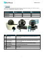
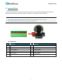
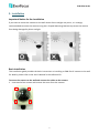
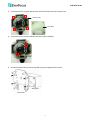
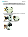
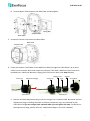
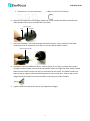
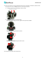
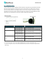
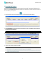
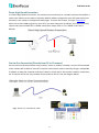
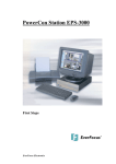
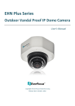
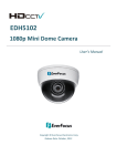
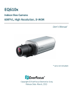
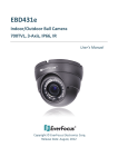
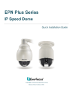
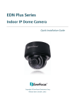
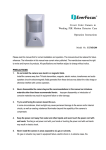
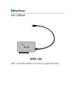
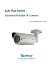
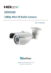
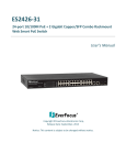
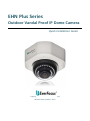
EHN Plus Series
Outdoor Vandal Proof IP Dome Camera
Quick Installation Guide
Copyright © EverFocus Electronics Corp,
Release Date: October, 2012
EHN Plus Series
1. Overview
The EHN Plus series vandal proof IP dome Camera is designed for outdoor use. The series comes in
three models: EHN3160 Plus / 3260 Plus / 3340 Plus.
Model Name
Megapixel
P-Iris
WDR
EHN3160 Plus
1.3 MP
Yes
Yes
EHN3260 Plus
2 MP
Yes
Yes
EHN3340 Plus
3 MP
Yes
No
Camera Module
8
7
6
1
3
2
4
5
No. Item Name
Descriptions
1
Cable Gland
Equipped with three plugs inserted in the cable conduits for
waterproofing.
2
LAN / PoE
Connects to a 10/100 Ethernet or PoE.
3
Terminal Block
A 12-pin terminal block. See Terminal Block later in this Quick
Installation guide.
4
Reset Button
Resets all configurations to the factory default settings.
5
SD / SDHC Slot
For inserting an SD / SDHC card
6
Lens
Varifocal lens with P-Iris control.
7
Light Sensor
Detects lights.
8
IR LEDs
33 IR LEDs for infrared illumination in night vision applications.
1
EHN Plus Series
System Requirement
Before installing, please check that your computer meets this system requirement.
•
•
Operating System: Microsoft Windows XP / Vista (32-bit) / 7 (32-bit)
Microsoft Internet Explorer 7 or above
Packing List
•
•
•
•
EHN Series Camera x 1
Base Plate Screw x 4
Screw Anchor x 4
Hexagon Screwdriver x 1
•
•
•
•
Desiccant Bag x 2
Inner Paper x 1
Software CD x 1
Quick Installation Guide x 1
Note: Contact the shipper if any items appear to have been damaged in the shipping process. If
any items are missing, notify your EverFocus Electronics Corp. Sales Representative or Customer
Service Branch. Please also keep the shipping carton for possible future use.
Optional Accessories
You can use the optional accessories to expand the capabilities and versatility of the camera. Please
contact your dealer for more information.
• One Adapter Plate with 4 Screws
The Adapter Plate is designed for wiring the cables
through the bottom of the camera case. For details on
how to wire the cables through the bottom of the
camera, please refer to the User’s Manual in the CD.
• L-Shaped Mounting Bracket
To prevent the camera from being damaged by direct
sunlight, it is strongly recommended to use the
L-Shaped Mounting Bracket to mount the camera to
the wall. For details on mounting the camera to the
wall using the L-Shaped Mounting Bracket, the User’s
Manual in the CD.
2
EHN Plus Series
2. Terminal Block
The I/O terminal block, located on the camera module, can be used to develop applications for
alarm input and output, two-way audio, TV-output or a variety of other functions.
Note:
1. You can unplug the terminal block from the camera module for easier wiring.
2. Microphones with external power supplies are required.
1 2 3 4 5 6
7 8 9 10 11 12
Camera Module
Pin Assignment
No.
Functions
No.
Functions
1
12V DC Input
7
Line Input C
2
Digital GND
8
Audio GND
3
Alarm Output C
9
Audio Output
4
Alarm COM C
10
Audio GND
5
Alarm Input C
11
CVBS Output
6
Digital GND
12
Digital GND
3
EHN Plus Series
3. Installation
Important Notice for the Installation
If you want to mount the camera on the wall where direct sunlight may occur, it is strongly
recommended to mount the camera using the L-Shaped Mounting Bracket to prevent the camera
from being damaged by direct sunlight.
Basic Installation
This installation guide provides the basic instructions on installing an EHN Plus IP camera to the wall.
For details, please refer to the User’s Manual in the software CD.
To mount the camera to the wall and connect the cables to the camera:
1. Unscrew the four screws and remove the cover from the camera.
4
EHN Plus Series
2. Unscrew the four screws and remove the Base Plate from the Camera Case.
Camera Case
Base Plate
3. Unscrew the two screws and take out the camera module.
4. Screw the Base Plate to the Wiring Box using the supplied four screws.
Wiring Box
Base Plate
5
EHN Plus Series
If you want to wire the cables through the bottom of the Camera Case, follow the steps below:
a. Remove the Circle Plate on the bottom of the Camera Case. You can simply loosen the Circle
Plate using a coin.
Circle Plate
Camera Case
b. Loosen and remove the Cable Gland from the Camera Case. Screw the Cable Gland to the
hole on the bottom of the Camera Case.
Cable Gland
Camera Case
c. Screw the Circle Plate to the side hole on the camera Case.
6
EHN Plus Series
d. Screw Adapter Plate between the Base Plate and Wiring Box.
Wiring Box
Adapter Plate
Base Plate
5. Screw the Camera Case back to the Base Plate.
Base Plate
Camera Case
6. Insert the network / PoE cable or the additional cables through the Cable Gland. Up to three
cables can be inserted. Note that except the network / PoE cable, additional wires have to be
bundled into a cable with diameter ranging from 5.3mm to 6.4mm (see Step d below).
Stopper Claw
Screw Cap
Screw Cap
Adjustment Ring(s)
Cable Gland
Stopper
Plug
Screw Body
Cable Gland
a. Remove the black Adjustment Ring if you are using a Cat 5 network cable. Note that the four
Adjustment Rings, including one black and three transparent rings, are attached on the
Cable Gland. If you are using a Cat 6 network cable, you can ignore this step. For details on
the Adjustment Rings, please refer to 3.1 Adjustment Rings in the User’s Manual.
7
EHN Plus Series
• Transparent x 3 (1 mm thickness)
• Black x 1 (0.5 mm thickness)
b. Remove the Plug(s) from the Stopper (depends on the number of cables inserted). One
Cable Conduit can only be inserted with one cable.
Cable Conduit
Plug
Stopper
c. Insert the network / PoE cable through the Cable Conduit, if your network / PoE cable
already has a RJ-45 connector, then you can use the Slitted Cable Conduit.
Slitted Cable Conduit
d. Optionally insert the additional wires, such as power (if you want to power the camera
through a 12V DC power source), alarm and audio cables, through the other Cable Conduit.
Note that one Cable Conduit can only be inserted with one cable. The Cable Conduit has
been tested to support cable diameter between 5.3mm and 6.4mm. Please refer to the
image below to bundle the lose wires before inserting to the Cable Conduit.
e. Tighten the Screw Cap all the way to the Adjustment Ring(s).
8
EHN Plus Series
f. Due to the variable cable diameters, for better waterproofing, it is strongly recommended
that you apply silicon sealants to the inner Screw Cap.
7. Connect the network / PoE cable to the LAN / PoE port on the camera module.
8. If you have inserted additional wires, connect the wires to the terminal block. Please refer to
2. Terminal Block for pin assignment.
9. Optionally insert an SD / SDHC card to the card slot.
SD Card Slot
10. Stick the supplied 2 desiccant bags inside the camera case.
Note: It is highly recommended to replace the desiccant bags every time when you open the
camera.
11. Place and screw the camera module back to the camera case.
9
EHN Plus Series
12. Access the camera live view for adjusting camera lens and angles. For details on how to access
the camera live view, see Step 6 and 7 in 4. Accessing the Camera.
a. To adjust camera lens, use the Zoom / Focus screws.
Zoom Screw
Focus Screw
b. To adjust the camera to a desired angle:
Pan Adjustment: Simply turn left / right for the top camera module.
360°
Tilt Adjustment: Using the two tilt screws.
64°
Rotational Adjustment: Using the rotate screw.
180°
13. Screw the cover back to the camera case.
10
EHN Plus Series
3.1 Adjustment Rings
The four Adjustment Rings, including one black and three transparent rings, attached on the Cable
Gland are used to tighten the cable gland for better waterproofing. The Cable Gland is designed
with three cable conduits for inserting the cables. You can insert a network cable (Cat 5 or Cat 6)
through one of the three conduits. And use the spare two conduits for inserting additional cables.
Please refer to the table below to verify the number of Adjustment Rings used.
Adjustment Rings
Adjustment Ring(s)
• Transparent x 3 (1mm thickness)
• Black x 1 (0.5mm thickness)
Cable Gland
Number of Cable used
One
Two
Three
Cable Type & Diameter
Number of Adjustment Ring Used
One Cat 5 (Φ 5.3mm)
Three Transparent Rings
One Cat 6 (Φ 6.4mm)
Three Transparent Rings + One Black Ring
One Cat 5 (Φ 5.3mm) +
One Additional Cable
One Cat 6 (Φ 6.4mm) +
One Additional Cable
One Cat 5 (Φ 5.3mm) +
Two Additional Cable
One Cat 6 (Φ 6.4mm) +
Two Additional Cables
Three Transparent Rings
Three Transparent Rings + One Black Ring
Three Transparent Rings
Three Transparent Rings + One Black Ring
** If you are using one / two / three cables (with Φ5.3mm), use three transparent rings.
** If you are using one / two / three cables (with Φ6.4mm), use three transparent rings and one
black ring.
11
EHN Plus Series
4. Accessing the Camera
You have to assign an IP address for your camera to be accessible. To assign an IP address to the
camera, use the IP Utility (IPU) software included in the software CD. Please connect the camera in
the same LAN of your computer.
1. Install and then start the IPU program
. The following dialog box appears.
2. Click Find Devices to search the cameras connected in the LAN. The default network values of
the cameras will be displayed.
Note: By default, the network protocol of the camera is DHCP.
3. To configure the network settings, select a camera and then click Login/Multi Login to log in.
4. Type the user ID and password. Click OK.
Note:
1. The default user ID is user1 and the default password is 11111111.
2. If you select more than one camera that has the same user ID / password, you will be able
to log in several cameras at once.
12
EHN Plus Series
5. To change the IP address, double-click the IP Address of the camera. Type a new IP address and
then click Set IP Address to save the settings.
You can also change the other settings by double-clicking the values. After configuring the
values, click Save Configuration.
Note: Most networks uses DHCP to assign IP addresses, if you are unsure of your network
settings, please consult your network administrators for configuration details.
6. To access the camera, highlight the camera and click Connect to Selected IP. The Internet
Explorer window pops up.
7. Type the user ID and password to log in. The Live View window of the camera appears.
Note:
1. You might be required to download ActiveX for viewing the camera feed. If asked, click Yes.
2. To enable Remove Live View, Firmware Upgrade and ActiveX Prompt on Internet Explorer,
some settings have to be complete. Please refer to 5.2 Settings for Microsoft Internet
Explorer in the User’s Manual.
13
EHN Plus Series
5. Connecting to the Network
You can use one of the methods below to connect the camera to the network.
Router or LAN Connection
This is the most common connection in which the IP camera is connected to a router and allows
multiple users on and off site to see the IP camera on a LAN/WAN (Internet). The camera must be
assigned an IP address that is compatible with its LAN. By setting up port forwarding on the router,
you can remotely access the cameras from outside of the LAN via the Internet. To remotely access
the Web interface of the IP camera, please refer to 7.3.2 DDNS in the User’s Manual. To set up port
forwarding, please consult the manual of the router.
Straight-through LAN patch cable
Right: Pinout of a straight-through cable.
14
EHN Plus Series
Direct High-Speed Connection
In a Direct High-Speed Connection, the camera connects directly to a modem without the need for a
router. You need to set the static or dynamic WAN IP address assigned by your ISP (Internet Service
Provider) in the camera’s configuration web pages. To access the camera, just type “http://xxx”,
where xxx is the IP address given by your ISP. If you have a dynamic IP address, this connection may
require that you use DDNS for a reliable connection. Please refer to 7.3.2 DDNS in the User’s
Manual.
One-to-One Connection (Directly from PC to IP camera)
You can connect directly without using a switch, router or modem. However, only the PC connected
to the camera will be able to view the IP camera. You will also have to manually assign a compatible
IP address to both the computer and the IP camera. Unless the PC has another network connection,
the IP camera will be the only network device visible to the PC. See the diagram below:
Pinout of straight patch cable
4. Assign IP Address
Right: Pinout of a crossed-over cable.
15
EHN Plus Series
6. Upgrading Firmware
You can upgrade camera’s firmware using the IP Utility software, which is included in the software
CD.
1. Follow Step 1 to Step 4 in 4. Assigning an IP Address to log in the camera.
2. Highlight the camera and then click Upgrade Firmware. A browsing window appears.
3. Select the firmware file (.evb) and then click Open. The IP Utility will automatically upgrade the
firmware.
The camera will reboot once the update is complete. Click Find Devices, the new firmware version
should be displayed in the last part of the Machine Name.
16
EverFocus Electronics Corp.
EverFocus Taiwan:
EverFocus Europe - Germany:
12F, No.79, Sec. 1, Shin-Tai Wu Road,
Hsi-Chih, Taipei, Taiwan
TEL: +886 2 2698 2334
FAX: +886 2 2698 2380
www.everfocus.com.tw
marketing@everfocus.com.tw
Albert-Einstein-Strasse 1, D-46446
Emmerich, Germany
TEL: +49 2822 93940
FAX: +49 2822 939495
www.everfocus.de
info@everfocus.de
EverFocus China - Beijing:
EverFocus China - Shenzhen:
Room 609, Technology Trade Building,
Shangdi Information Industry Base,
Haidian District, Beijing 100085, China
TEL: +86 10 6297 3336~39
FAX: +86 10 6297 1423
www.everfocus.com.cn
marketing@everfocus.com.cn
4F, No. 2, D4 Building, Wan Yelong
Industrial Park, Tangtou Road, Shiyan,
Baoan, Shenzhen, Guangdong 518101, China
TEL: +86 755 2765 1313
FAX: +86 755 2765 0337
www.everfocus.com.cn
marketing@everfocus.com.cn
EverFocus USA - California:
EverFocus USA - New York:
1801 Highland Avenue, Unit A, Duarte, CA 91010, USA
TEL: +1 626 844 8888
FAX: +1 626 844 8838
www.everfocus.com
sales@everfocus.com
415 Oser Avenue, Unit S, Hauppauge, NY 11788, USA
TEL: +1 631 436 5070
FAX: +1 631 436 5027
www.everfocus.com
sales@everfocus.com
EverFocus Japan:
EverFocus Europe - UK:
5F, Kinshicho City Building, 2-13-4
Koto-Bashi,Sumida-Ku, Tokyo, 130-0022, Japan
TEL: +81 3 5625 8188
FAX: +81 3 5625 8189
www.everfocus.co.jp
info@everfocus.co.jp
Unit 12, Spitfire Business Park,
Hawker Road, Croydon Surrey, CR0 4WD, UK
TEL: +44 20 8649 9757 / +44 845 430 9999
FAX: +44 20 8649 9907
www.everfocusuk.co.uk
salesuk@everfocus.com
EverFocus India:
Suite 803, Housefin Bhavan, C-21,
Bandra Kurla Complex, Bandra (East),
Mumbai 400051, India
TEL: +91 22 6128 8700
FAX: +91 22 6128 8705
www.everfocus.in
sales@everfocus.in
Your EverFocus product is designed
and manufactured with high quality
materials and components which can
be recycled and reused.
This symbol means that electrical and
electronic equipment, at their
end-of-life, should be disposed of
separately from your household waste.
Please, dispose of this equipment at
your local community waste
collection/recycling centre.
In the European Union there are
separate collection systems for used
electrical and electronic product.
Please, help us to conserve the
environment we live in!
Ihr EverFocus Produkt wurde entwickelt
und hergestellt mit qualitativ
hochwertigen Materialien und
Komponenten, die recycelt und wieder
verwendet werden können.
Dieses Symbol bedeutet, dass
elektrische und elektronische Geräte am
Ende ihrer Nutzungsdauer vom
Hausmüll getrennt entsorgt werden
sollen.
Bitte entsorgen Sie dieses Gerät bei
Ihrer örtlichen kommunalen
Sammelstelle oder im Recycling Centre.
Helfen Sie uns bitte, die Umwelt zu
erhalten, in der wir leben!
P/N: 4605PH3160B010A-Ver.C