1
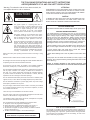
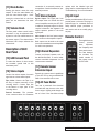
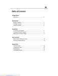
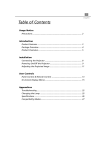
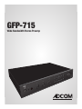
GFP-715
Wide Bandwidth Stereo Preamp
vo lu m
e
ta pe
tu ne r
ph on o
au x
CD
m ut e
e
ba la nc
to ne
in
m on o
ta pe
m on
ex t. pr
oc
tr eb le
ba ss
1 5
P - 7
G F
ph on e
ADCOM GFP-715 Owner’s Manual | 1
ABOUT ADCOM
PERFORMANCE AND VALUE
In the world of high performance electronics, Adcom has done the impossible: make state-ofthe-art components that are easy to use at an affordable price. In doing this, Adcom has created
a revolution in the world of consumer electronics. By creating some of the most renowned components and offering them at affordable prices, Adcom has enabled more people to enjoy their
favorite music and movies at top performance levels. Perhaps Audio Magazine said it best: “No
competing company I know can provide a similar balance of sound quality, power and affordability.”
AWARD WINNING
Innovation is our stronghold, and our numerous awards year after year prove that we’re never
satisfied to rest on our reputation. From our legendary high current amplifiers to our state-of-theart digital processors, Adcom components consistently impress even the most demanding audiences. Adcom components have won over 25 Product of the Year and Special Recognition citations
from Audio Video International, 3 Diapason D’Or Awards, 7 Consumer Electronics Show Design and
Engineering Awards, and have appeared on Stereophile’s “Recommended Components” lists over
70 times since 1988. A reputation worth its weight in gold.
ENGINEERING PASSION
Every Adcom component is not only designed to reproduce the highest quality sound and picture,
but to also deliver the greatest possible value. It is our engineers’ passion for perfection that has
enabled our components to be judged the equivalent of others costing two, three, or even five
times as much. Our engineering team consistently strives to develop and design products that
will exceed your expectations. Our goal at Adcom is to let more consumers hear high-end quality
sound and see high-end video without paying high-end prices.
All Adcom components are the result of a long-standing dedication to innovation, quality, simplicity and value. Adcom, we have the power, and now so do you.
ADCOM
A division of Klein Technology Group, LLC
8541 East Anderson Drive
Scottsdale, Arizona 85255 USA
Telephone: (480) 607-2277
Fax: (480) 348-9876
Email: info@adcom.com
Web: www.adcom.com
ADCOM is a registered trademark of Klein Technology Group, LLC.
Copyright © 2003 Klein Technology Group, LLC. All rights reserved. No part of this manual may be reproduced
2 | ADCOMorGFP-715
Owner’s
Manual without the express written consent of Klein Technology Group, LLC.
electronically
transmitted
TABLE OF CONTENTS
Welcome . . . . . . . . . . . . . . . . . . . . . . . . . . . . . . 2
Table of Contents . . . . . . . . . . . . . . . . . . . . . . 3
Precautions and Warnings . . . . . . . . . . . . . . . 4
Introduction & Key Features . . . . . . . . . . . . . 5
Safety Information . . . . . . . . . . . . . . . . . . . . . 5
Front Panel Illustration . . . . . . . . . . . . . . . . . 6
Rear Panel Illustration . . . . . . . . . . . . . . . . . . 6
Description of Front Panel . . . . . . . . . . . . 6-7
Description of Rear Panel. . . . . . . . . . . . . . . . 7
Remote Control Illustration . . . . . . . . . . . . . . 7
Troubleshooting . . . . . . . . . . . . . . . . . . . . . .
8
Service Information . . . . . . . . . . . . . . . . . . 8-9
Warranty . . . . . . . . . . . . . . . . . . . . . . . . . . . . . . 9
Your Responsibilites . . . . . . . . . . . . . . . . . . . . 9
GFP-715 Specifications . . . . . . . . . . . . . . . . 10
ADCOM GFP-715 Owner’s Manual | 3
N
OCK
THE FOLLOWING PRECAUTIONS AND SAFETY INSTRUCTIONS
ARE REQUIREMENTS OF UL AND CSA SAFETY REGULATIONS
Warning: To reduce the risk of fire or electric shock, do
not expose this unit to rain or moisture.
CAUTION
RISK OF ELECTRIC SHOCK
DO NOT OPEN
CAUTION
The graphic symbol of a lightning flash with an
arrow point within a triangle signifies that there
is dangerous voltage within the unit and it poses
a hazard
to anyoneSHOCK
removing the cover to gain
RISK
OF ELECTRIC
access to the interior of the unit. OnIy qualified
DO
NOT
OPEN
service personnel should make any such attempt.
The graphic symbol of an exclamation point within
an equilateral triangle warns a user of the device
that it is necessary to refer to the instruction manual
and its warnings for proper operation of the unit.
Do not place this unit on an unstable cart, stand, tripod,
bracket, or table. The unit may fall, causing serious
injury to a child or adult, and serious damage to the
unit. Use only with a cart, stand, tripod, bracket, or
table recommended by the manufacturer or sold with
the unit. Any mounting of the device should follow the
manufacturer’s instructions, and should use a mounting
accessory recommended by the manufacturer.
ATTENTION
POUR PREVENIR LES CHOCS ELECTRIQUES NE PAS UTILISER CETTE FICHE
POLARISEE AVEC UN PROLONGATEUR, UNE PRISE CE COURANT OU UNE
AUTRE SORTIE CE COURANT, SAUF SI LES LAMES PEUVENT ETRE INSEREES
A FOND SANS EN LAISSER AUCUNE PARTIE A DECOUVERT.
CAUTION
TO PREVENT ELECTRIC SHOCK DO NOT USE THIS POLARIZED PLUG WITH
AN EXTENSION CORD, RECEPTACLE OR OTHER OUTLET UNLESS THE
BLADES CAN BE FULLY INSERTED TO PREVENT BLADE EXPOSURE.
CAUTION POWER LINES
Any outdoor antenna must be located away from all power lines.
OUTDOOR ANTENNA GROUNDING
If an outside antenna is connected to your tuner or tuner/preamplifier,
be sure the antenna system is grounded so as to provide some protection
against voltage surges and built-up static charges. Section 810 of the
National Electrical Code, ANSI/NFPA No. 701984, provides information
with respect to proper grounding of the mast and supporting structure,
grounding of the lead-in wire to an antenna discharge unit, size of
grounding conductors, location of antenna discharge unit, connection to
grounding electrodes, and requirements for the grounding electrode.
a. Use No.10 AWG (5.3 mm2) copper, No.8 AWG (8.4 mm2) aluminum, No.17
AWG (1.0 mm2) copper clad steel or bronze wire, or larger, as a ground wire.
b. Secure antenna lead-in and ground wires to house with stand-off
insulators spaced from 46 feet (1.221.83 m) apart.
Read all the safety and operating instructions before connecting or using
this unit.
c. Mount antenna discharge unit as close as possible to where lead-in enters
house.
Retain this notice and the owner’s manual for future reference.
d. Use jumper wire not smaller than No.6 AWG (13.3 mm2) copper, or the
equivalent, when a separate antenna grounding electrode is used. See NEC
Section 810-21 (j).
All warnings on the unit and in its operating instructions should be adhered to.
All operating and use instructions should be followed.
Do not use this unit near water. For example, near a bathtub, washbowl,
kitchen sink, laundry tub, in a wet basement, or near a swimming pool.
EXAMPLE OF ANTENNA GROUNDING AS PER NATIONAL ELECTRICAL CODE
INSTRUCTIONS CONTAINED IN ARTICLE 810. RADIO AND TELEVISION EQUIPMENT.
power lines
The unit should be installed so that its location or position does not interfere
with its proper ventilation. For example, it should not be situated on a
bed, sofa, rug, or similar surface that may block the ventilation openings;
or placed in a built-in installation, such as bookcase or cabinet, that may
impede the flow of air through its ventilation openings.
ground clamp
service entrance
conductors
standoff
insulators, b
The unit should be situated away from heat sources such as radiators, heat
registers, stoves, or other devices (including amplifiers) that produce heat.
mast
The unit should be connected to a power supply outlet only of the voltage
and frequency marked on its rear panel.
The power supply cord should be routed so that it is not likely to be walked
on or pinched, especially near the plug, convenience receptacles, or where
the cord exits from the unit.
service
entrance
equipment
antenna
lead-in wire
ground wire, a,b
ground clamps
antenna
discharge
unit, c
Clean unit only as recommended in its instruction manual.
The power supply cord of the unit should be unplugged from the wall outlet
when it is to be unused for a long period of time.
Care should be taken so that objects do not fall, and liquids are not spilled,
into the enclosure through any openings.
This unit should be serviced by qualified service personnel when:
A. The power cord or the plug has been damaged; or
B. Objects have fallen, or liquid has been spilled, into the unit; or
C. The unit has been exposed to rain, or liquids of any kind; or
D. The unit does not appear to operate normally, or exhibits a marked
change in performance; or
E. The device has been dropped, or the enclosure damaged.
DO NOT ATTEMPT SERVICING OF THIS UNIT YOURSELF.
SERVICING
TO QUALIFIED
4REFER
| ADCOM
GFP-715
Owner’s SERVICE
ManualPERSONNEL.
to external antenna
terminals of radio receiver
power service grounding
electrode system
(e.g. interior metal water pipe)
bonding jumper, d
ground wire, a,b
ground clamps
optional antenna grounding
electrode driven 8 feet (2.44 M) into
the earth if required by local codes.
NOTE TO CATV SYSTEM INSTALLER
This reminder is provided to call the CATV system installer’s attention to
Article 82022 of the National Electrical Code that provides guidelines for
proper grounding and, in particular, specifies that the cable ground shall
be connected to the grounding system of the building, as close to the
point of cable entry as practical.
Introduction
Congratulations on your decision to
purchase the GFP-715 stereo preamplifier.
Two channel audio is better than ever!
The new DVD Audio and SACD formats
can support a wider frequency spectrum
(100kHz) and greater dynamic range
(144dB) than conventional CD. The GPF715 is designed to capture all the fidelity
that high resolution audio has to offer,
with precision broadband components
and an ultra low noise floor. Equipped
with a processor loop, a tape loop and
a phono stage, this new ADCOM preamp
hasn’t forgotten about your legacy
components. Audition the GFP-715 paired
with an ADCOM power amp and DVD
player and rediscover the magic of two
channel. To realize the full potential of
your new stereo preamplifier, and before
making any connections to it, please
read these operating and installation
instructions thoroughly.
Key Features
• Class A line level preamp
• high resolution audio bandwidth
• 4 audio inputs
• 1 phono input stage
• tape output w/ monitor function
• external processor loop
• bass, treble, and balance adjust
• front panel headphone input
• remote control
Unpacking the GFP-715
Before your new ADCOM preamplifier
left our factory, it was carefully
inspected for physical imperfections
and
tested
for
all
electrical
parameters as a routine part of
ADCOM’s systematic quality control.
This, along with full operational and
mechanical testing, should ensure a
product flawless in both appearance
and performance. After you have
unpacked the GTP-715, inspect it for
physical damage. Save the shipping
carton and all packing material as they
are intended to reduce the possibility
of transportation damage should the
preamplifier ever need to be shipped
again. In the unlikely event damage
has occurred, notify your dealer
immediately and request the name of
the carrier so a written claim to cover
shipping damages can be initiated. The
right to a claim against a public carrier
can be forfeited if the carrier is not
notified promptly in writing and if the
shipping carton and packing materials
are not available for inspection by
the carrier. Save all packing materials
until the claim has been settled.
Placing the GFP-715
Although the GFP-715 does not
generate much heat, it is good practice
to ensure the amplifier’s long-term,
trouble-free operation to provide
adequate ventilation for the unit.
Therefore, the GFP-715 should be kept
away from external sources of heat
such as radiators and hot-air ducts.
We recommend that you exercise
care when placing components on top
of the GFP-715. If you are placing a
heat producing component (such as an
amplifier) on top of or below the GFP715, it is recommended that you allow
at least 3 inches vertical spacing for
proper airflow.
If your system includes the use of the
phono input, you may find that placing
components above or under the GFP-715
may induce hum, caused by the proximity
of their power transformer to the phono
cables or input jacks. If this should occur,
moving the components will usually help
reduce the hum.
If you observe these recommendations,
the GFP-715 will perform reliably
in any reasonable environment. You
should also pay attention to such
normal considerations as protection
from excessive dust and moisture.
Occasional vacuuming of accumulated
dust on the chassis panels and around
the ventilating slots should be all that
is required.
The optimal perfomance of your new
GFP-715 will ultimately depend on
the care with which you make the
connections between the amplifier,
preamplifier and loudspeakers. All
input and output signal connections
should be made only with high quality,
low-loss, low capacitance cables. For
recommendations of the type and
quality of interconnections that are
best for your applications, consult with
your ADCOM retailer.
Safety Information
There are no user serviceable parts
inside. Refer all servicing to qualified
service personnel.
The unit must be connected to a power
supply only of the type and voltage
specified on the rear panel. Connect
the component to the power outlet
only with the supplied power supply
cable or an exact equivalent. Do not
modify the supplied cable. Do not
defeat grounding and/or polarization
provisions. The cable should be
connected to a 3-pin polarized wall
outlet, matching the wide blade of the
plug to the wide slot of the receptacle.
Do not use extension cords. Do not
route the power cord where it will
be crushed, pinched, bent, exposed
to heat, or damaged in any way. Pay
particular attention to the power cord
at the plug and where it exits the back
of the unit. The power cord should be
unplugged from the wall outlet if the
unit is to be left unused for a long
period of time. Immediately stop using
the component and have it inspected
and/or serviced by a qualified service
agency if:
• the power supply cord or plug has
been damaged;
• objects have fallen or liquid has
been spilled into the unit;
• the unit has been exposed to rain;
• the unit shows signs of improper
operation; or
• the unit has been dropped or
damaged in any way.
ADCOM GFP-715 Owner’s Manual | 5
1
2
5
4
3
6
14
Description of Unit:
Front Panel
[1] On/Off Power Switch
The GFP-715 is turned on by pressing
either the remote control power button
or toggling the front panel power
switch. When on, the LED indicator in
the button will illuminate.
[2] Headphones Jack
Headphones may be used through the use
of the phones output jack on the front
pael. This jack will accept a standard 1⁄4”
stereo headphone plug.
[3] IR Sensor
This lens protects the infrared reciever
which receives commands from the
remote control. Note: the pathway
between the lens and remote control
must be free of obstruction for the
remote control to operate the GFP-715.
6 | ADCOM GFP-715 Owner’s Manual
15
16
12
10
8
13
11
9
7
17
18
19
[4] Bass and Treble Knobs [7] Tone In Button
The bass and treble knobs contol the
bass and treble frequencies by increasing
or decreasing levels.
This button is used to engage the bass
and treble controls. In the out position,
the tone controls will have no effect.
[5] Balance Knob
[8] Mono Button
Balance control provides adjustment for
greater accuracy of stereo imaging.
The mono setting combines both left
and right channels for a monaural input
signal or where speaker placement does
not accommodate stereo playback.
[6] Source Selections
These five buttons select the source you
desire for listening. When you select
CD, tuner, phono or video/aux, these
signals are routed to the tape output
for recording the selected source. Tape
playback is accessed by pressing the
tape button. The presence of signal at
the tape outputs can be confirmed by
pressing the tape monitor button. The
five source select buttons are also on the
remote control.
[9] Tape Monitor
Confirms that signals are present at tape
outputs. If a three-head tape recorder
is connected, activating this circuit
will allow direct monitoring from the
recording. See tape recorder manual for
details.
[10] External Processor
Selects an exteranl audio precessor, i.e.,
surround sound processor or equalizer.
[11] Mute Button
Pressing this button mutes the main
outputs. To turn the mute feature off,
press the mute button again. Note:
turning the volume knob on the front
panel will not deactivate the mute
feature.
[12] Volume Knob
The front panel volume control knob is
motorized. It may be adjusted either
by hand or with the volume buttons on
the remote control. The volume knob’s
illuminated LED always indicates the
volume level.
Description of Unit:
Rear Panel
[13] GND Ground Post
To reduce the chance for hum connect
the turntable ground lead to this
attachment point.
[14] Stereo Inputs
Connect the various outputs from each
signal source to these stereo inputs.
Tape In/Out: Connect the Tape In to
the Play or Output connection of the
recording device. Connect Tape Out
to the Record or Input jacks of the
recording device.
External Processor: The processor
in/out connectors allow for convenient
connection of an external processor or
an equalizer. Consult the manual of your
external processor.
replace with the identical type and
rating fuse for continued protection. See
“Troubleshooting” for more information.
[15] Stereo Outputs
[16] AC Input
Bypass Output: The signal path from
this output does not include the tone
control amplifiers used by the GFP-715.
In addition, the bypass output is a direct
coupled connection that bypasses the
output capacitor present in the main
signal path.
Use the provided standard IEC AC cord to
provide power to the unit. The plug is a
polarized type, for continued electrical
safety observe proper polariztion at
main outlet and do not modify plug in
any way.
Main Output: A line level stereo output
that connects to the amplifier’s inputs.
Remote Control
Both outputs can be used at the same
time to accommodate a second amplifier
for multi-room operation.
[16] Infrared Repeaters
Connect an infrared repeater, such as
the ADCOM IRA-500II, to control other
remote controlled components via the
remote sensor extension.
[17] Remote Sensor
Extension Input
CD
power
tuner
volume
tape
video/aux
phono
ext. proc
mute
The supplied remote
control,
pictured
here,
duplicates
the frequently used
front panel controls.
Two AAA batteries
are included. The
model number of
the remote control
is GFP-710RC.
Expand the remote control capabilities
of the GFP-715 by using an ADCOM XR500II via an external room or zone.
[18] AC Fuse Holder
This unit is protected from electrical
overloads that may be sent to the unit
from a surge or lighting strike though the
use of a fuse. If the fuse blows always
ADCOM GFP-715 Owner’s Manual | 7
SYMPTOM
POSSIBLE REASON
POSSIBLE SOLUTION
Power LED does not
AC Power Cord(s) not plugged in.
Plug in AC Power Cord(s).
glow. No sound
AC Fuse(s) failed.
Transformer thermal protection engaged.
I2V DC triggering malfunctioning.
Replace AC Fuse(s).
Wait until unit cools down. It will reset.
Reset power switch manually. Check
Power LED glows,
but no sound
Preamp or source unit is not on.
Connections in rear of amp are loose.
connection of 12V DC trigger at source.
Make sure whole system is on.
Verify all connections on rear of amp.
One channel not
producing sound
INPUT(s) or OUTPUT(s) connector
disconnected or loose.
Verify both connections on that channel.
Hum from all speakers
at any volume
Speaker disconnected.
Internal protection engaged.
Ground loop (difference in ground voltages
between components).
Verify connection at speaker.
Bring to Dealer or Service Center.
If Cable TV is present (see Note 1).
If Cable TV is not present (see Note 2).
Hum from all speakers
(hum goes up or
down with volume)
Problem with source unit (CD, tape, etc.),
or RCA cable connecting that source unit
to the preamp.
Try different source (tuner, tape, etc.)
and/or different RCA cable.
Hum from the amplifier
itself
Some major appliance, dimmer, halogen or
fluorescent light is creating interference.
Make sure all appliances, dimmers and
suspect lights are off.
Troubleshooting
Use the troubleshooting notes above to solve common
situations that don’t require professional attention. If the
steps stated in possible solution do not resolve your problem, then please contact your ADCOM dealer or call the
ADCOM customer service department. Any problems not
covered here should be brought to the attention of your
ADCOM dealer or ADCOM customer service department.
A special note on “hum:” When there is a low-volume
“hum” audible throughout your speakers, even with the
main volume turned all the way down, you have a common phenomenon known as a “ground loop.” A ground loop
is basically a difference in ground voltages between two
or more components which are connected electrically and
which creates multiple current paths where there must only
be one. This difference in potentials creates a 60Hz lowlevel sound (approximately a low A), that seems to “hum.”
It can be caused by adding new components to your system,
but that does not imply there is anything electrically wrong
with any new component. With the advent of audio/video
and home theater systems, the problem has become commonplace. Generally, the cause is the Cable-TV incoming
signal line. This new incoming line may add an additional
ground at a different potential to the AC line ground of
your other equipment (refer to note I and 2, to troubleshoot a hum problem).
Note 1: Cable TV systems can sometimes contribute to
ground loop problems which cause “hum.” To determine
if your cable system is the contributing factor, disconnect
the Cable-TV incoming signal line (round, 75Ω) at the wall,
8 | ADCOM GFP-715 Owner’s Manual
or the first component the cable is connected to (i.e. the
cable box, or VCR). If the hum is no longer present, you
must insert a “75Ω ground loop isolator” before reconnecting the line. You should check with your ADCOM dealer to
obtain one. If the “75Ω ground loop isolator” works only
partially or not at all, then please read note 2 to complete
the troubleshooting procedure.
Note 2: Make sure that the power amplifier is at least 6”
from processor or other equipment using microprocessors.
Usually putting another component between them is sufficient to minimize the hum. If this does not reduce the
hum, turn the system off and disconnect all Inputs from
the amplifier. If the hum still persists, then your dealer or
service center must examine the unit/system. If the hum
disappears, try another set of RCA cables. Connect one RCA
cable at a time to see if one specific cable is responsible.
If any or all cables cause the hum to appear, then the unit
should be evaluated for proper operation by your dealer or
authorized service center. Please see our website or call us
for a list of authorized service centers in your area.
Servicing
ADCOM has a technical service department to answer
questions pertinent to the installation and operation of your
unit. In the event of difficulty, please contact us for prompt
advice. If your problem cannot be resolved through our
combined efforts, we may refer you to an authorized repair
agency, or authorize return of the unit to our factory. To aid
us in directing you to a convenient service center, it would
be helpful if you indicate which major city is accessible to
your home.
Please address mail inquires to:
ADCOM Service
8541 East Anderson Drive
Scottsdale, Arizona 85255 USA
of original purchase from an ADCOM authorized dealer.
During this period, ADCOM will repair or replace a defective
product or part, at our option, with a new or refurbished
product or part without charge to you, as long as you follow
the procedures listed below.
Phone, Fax or Email inquires to:
Voice: (480) 607-2277 or Fax: (480) 348-9876
Monday through Friday, 8:00 AM to 4:00 PM MST
Email: service@adcom.com
All implied warranties, including implied warranties of
merchantability and fitness for a particular purpose are
limited in duration to the duration of the warranty period.
For fax inquires, please include a return fax number for the
reply. When calling or writing about your ADCOM product,
be sure to note and refer to its serial number as well as
the date of purchase and the dealer from whom it was
purchased. In any communications to us, please include
a daytime phone number where we may reach you. In
the event the unit must be returned to our factory for
service, you will be instructed on the proper procedure
when you call or write for a return authorization. Under no
circumstances should your unit be shipped to our factory
without prior authorization, or packed in other than its
original carton and fillers.
If the original shipping carton and its fillers have been lost,
discarded, or damaged, a duplicate carton may be obtained
from our service department for a nominal charge.
Always ship prepaid via United Parcel Service (UPS) or other
approved carrier. Do not ship via parcel post, since the
packing was not designed to withstand rough parcel post
handling. Improper shipment of the product will void your
warranty coverage.
Warranty
ADCOM, a division of Klein Technology Group, LLC, makes
the following limited warranties. These limited warranties
extend to the original purchaser or any person receiving this
product as a gift from the original purchaser and to no other
purchaser or transferee. There is no warranty provided by
ADCOM for products purchased from unauthorized outlets
or dealers or from previous owners.
Limited Five Year Warranty (Home, Non-Commercial Use Only)
ADCOM warrants this product against defects in materials or
workmanship for a period of five (5) years after the date of
original retail purchase from an ADCOM authorized dealer.
During this period, ADCOM will repair or replace a defective
product or part, at our option, with a new or refurbished
product or part without charge to you, as long as you follow
the procedures listed below.
This warranty excludes all incidental and consequential
damages, unless contravened by state law. This warranty
gives you specific rights and you may have other rights
which vary from state to state.
No person, agent, distributor, dealer, or company is
authorized to change, modify or extend the terms of these
warranties in any manner whatsoever.
Your Responsibilities
The above warranties are subject to the following conditions:
(1) You must retain and present your dated invoice or bill
of sale to provide proof of original purchase from an ADCOM
Authorized Dealer and coverage under the warranty period.
(2) You must notify us within ten (10) days after you
discover a defective product or part.
(3) All warranty servicing of this product must be done by
ADCOM or an authorized ADCOM Service Center.
(4) This warranty is only valid if this product has been
purchased and used in the United States. Warranty coverage
for products purchased and used outside of the United
States is provided by local ADCOM authorized distributors.
(5) Charges by third parties for set-up, installation,
adjustments, shipment, insurance, and other charges are
not covered by this warranty.
(6) This warranty extends only to defects in material or
workmanship as limited above and does not extend to any
product or part which has been lost or discarded by you, or
to damage to products or parts caused by misuse, accident,
Acts of God such as lightning or fluctuations in electrical
power, improper installation, improper maintenance or use in
violation of instructions provided in this Owner’s Manual, or to
products which have been altered or modified. This warranty
does not extend to products which have had the serial number
removed, altered, defaced, or rendered illegible.
(7) Physically damaged products are not covered by this
warranty and will be returned as received without repair.
Limited Ninety (90) Day Warranty (Commercial Use Only)
ADCOM warrants this product against defects in materials or
workmanship for a period of ninety (90) days after the date
ADCOM GFP-715 Owner’s Manual | 9
GFP-715 Specifications
Output Impedance
Bypass/Main Outputs . . . . . . . . . . . . . . . . . . . . . . . . . . . . . . . . . . . . . . . . . . . . . . . . . . . . . . . . . . . . . . . . . 100 Ohms
Tape Outputs . . . . . . . . . . . . . . . . . . . . . . . . . . . . . . . . . . . . . . . . . . . . . . . . . . . . . . . . . . . . . . . . . . . . . . . 475 Ohms
Output Level
Bypass / Main Outputs . . . . . . . . . . . . . . . . . . . . . . . . . . . . . . . . . . . . . . . . . . . . . . . . . . . . . . . . . . . . . . . . . . . 2.0 Vrms
Output Level (Maximum)
Bypass / Main Outputs . . . . . . . . . . . . . . . . . . . . . . . . . . . . . . . . . . . . . . . . . . . . . . . . . . . . . . . . . . . . . . . . . . 10.0 Vrms
Frequency Response (±0.5dB)
High Level . . . . . . . . . . . . . . . . . . . . . . . . . . . . . . . . . . . . . . . . . . . . . . . . . . . . . . . . . . . . . . . . . . . . . . . . 5Hz-100kHz
Phono . . . . . . . . . . . . . . . . . . . . . . . . . . . . . . . . . . . . . . . . . . . . . . . . . . . . . . . . . . . . . . . . . . . . . . . . . . . . 5Hz-50KHz
THD + Noise (@ rated output 20Hz - 20kHz)
High Level . . . . . . . . . . . . . . . . . . . . . . . . . . . . . . . . . . . . . . . . . . . . . . . . . . . . . . . . . . . . . . . . . . . . . . . . . . . . 0.005%
Phono . . . . . . . . . . . . . . . . . . . . . . . . . . . . . . . . . . . . . . . . . . . . . . . . . . . . . . . . . . . . . . . . . . . . . . . . . . . . . . . . 0.005%
Intermodulation Distortion (SMPTE @ rated output)
High Level . . . . . . . . . . . . . . . . . . . . . . . . . . . . . . . . . . . . . . . . . . . . . . . . . . . . . . . . . . . . . . . . . . . . . . . . . . . . 0.005%
Phono . . . . . . . . . . . . . . . . . . . . . . . . . . . . . . . . . . . . . . . . . . . . . . . . . . . . . . . . . . . . . . . . . . . . . . . . . . . . . . . 0.005%
Signal to Noise (@ rated output - A weighted)
High Level . . . . . . . . . . . . . . . . . . . . . . . . . . . . . . . . . . . . . . . . . . . . . . . . . . . . . . . . . . . . . . . . . . . . . . . . . . . ≥100dB
Phono . . . . . . . . . . . . . . . . . . . . . . . . . . . . . . . . . . . . . . . . . . . . . . . . . . . . . . . . . . . . . . . . . . . . . . . . . . . . . . . . ≥95dB
Input Impedance
High Level . . . . . . . . . . . . . . . . . . . . . . . . . . . . . . . . . . . . . . . . . . . . . . . . . . . . . . . . . . . . . . . . . . . . . . . . . . . . . 25KΩ
Phono . . . . . . . . . . . . . . . . . . . . . . . . . . . . . . . . . . . . . . . . . . . . . . . . . . . . . . . . . . . . . . . . . . . . . . . . . . . . . . . . . 47kΩ
Input Sensitivity (@ rated output)
High Level . . . . . . . . . . . . . . . . . . . . . . . . . . . . . . . . . . . . . . . . . . . . . . . . . . . . . . . . . . . . . . . . . . . . . . . . . . . . 205 mV
Phono . . . . . . . . . . . . . . . . . . . . . . . . . . . . . . . . . . . . . . . . . . . . . . . . . . . . . . . . . . . . . . . . . . . . . . . . . . . . . . . . 2.4mV
RIAA accuracy (20Hz - 20kHz)
Phono . . . . . . . . . . . . . . . . . . . . . . . . . . . . . . . . . . . . . . . . . . . . . . . . . . . . . . . . . . . . . . . . . . . . . . . . . . . . . . ± 0.25dB
Tone Controls
Bass (20Hz) . . . . . . . . . . . . . . . . . . . . . . . . . . . . . . . . . . . . . . . . . . . . . . . . . . . . . . . . . . . . . . . . . . . . . . . . . ± 11.5dB
Treble (20kHz) . . . . . . . . . . . . . . . . . . . . . . . . . . . . . . . . . . . . . . . . . . . . . . . . . . . . . . . . . . . . . . . . . . . . . . . . ± 8.5dB
General
Power (available in 230VAC by special order) . . . . . . . . . . . . . . . . . . . . . . . . . . . . . . . . . . . . . . . . . . 115VAC—50/6OHz
Chassis Dimensions . . . . . . . . . . . . . . . . . . . . . . . . . . . . . . . . . . . . . . 3” (76.2mm) x 17” (432mm) x 11.5” (292.1mm)
Maximum Dimensions . . . . . . . . . . . . . . . . . . . . . . . . . . . . . . . . . . 3.5” (88.9mm) x 17” (432mm) x 12.5” (317.5mm)
Weight . . . . . . . . . . . . . . . . . . . . . . . . . . . . . . . . . . . . . . . . . . . . . . . . . . . . . . . . . . . . . . . . . . . . . . . . . . 12 lbs. (5.5kg)
Weight, Packed . . . . . . . . . . . . . . . . . . . . . . . . . . . . . . . . . . . . . . . . . . . . . . . . . . . . . . . . . . . . . . . . . . . 15 lbs. (6.8kg)
10 | ADCOM GFP-715 Owner’s Manual
Installer’s Notes
ADCOM GFP-715 Owner’s Manual | 11
ADCOM
A division of Klein Technology Group, LLC
8541 East Anderson Drive
Scottsdale, Arizona 85255
Voice: (480) 607-2277
Fax: (480) 348-9876
http://www.adcom.com
12 | ADCOM GFP-715 Owner’s Manual
GFP715_manual_v1