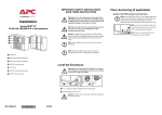
1
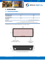
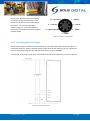
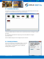
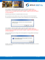
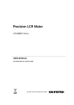
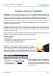
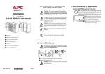
HIBEAM Load Display Model HBD100 Installation and User Manual V1.5: 7/10/2013 CONTENTS 1 OVERVIEW ....................................................................................................................................... 4 2 SPECIFICATIONS .............................................................................................................................. 5 2.1 Physical Specifications ............................................................................................................ 5 2.2 Electrical Specifications........................................................................................................... 6 2.3 Communication Specifications................................................................................................ 6 3 INSTALLATION DETAILS ................................................................................................................... 7 3.1 Prior to Installation ................................................................................................................. 7 3.2 Wiring Details .......................................................................................................................... 7 4 3.2.1 Connecting the Power Supply .................................................................................. 7 3.2.2 Connecting Load Sensor Inputs ................................................................................ 7 3.2.3 Connecting the Fault Output.................................................................................... 8 COMMISSIONING DETAILS .............................................................................................................. 9 4.1 Installing and Launching the FSU Application ......................................................................... 9 4.1.1 FSU Program Installation.......................................................................................... 9 4.1.2 Installing the FSU application ................................................................................... 9 4.1.3 Launching the application ........................................................................................ 9 4.2 Connecting to the Device ...................................................................................................... 10 4.3 Checking for Firmware .......................................................................................................... 10 4.4 General Tab ........................................................................................................................... 12 4.4.1 Setting Equipment Name ....................................................................................... 12 4.4.2 Test Display ............................................................................................................ 12 4.4.3 Auto Tare................................................................................................................ 12 4.5 Load Input Configuration ...................................................................................................... 13 4.5.1 Input Selection ....................................................................................................... 13 4.5.2 Using/Removing a HoistNet Input ......................................................................... 14 4.5.3 Amplification and the Signal Indicator ................................................................... 15 4.5.4 Units ....................................................................................................................... 16 4.5.5 Display Hysteresis .................................................................................................. 16 4.5.6 Calibration (with a directly connected load cell, or the F-Link input option) ........ 16 © CASWA Pty Ltd – 2013 2 | Page 4.5.7 Calibration (Using the 0-10V input from a ControlPro) ......................................... 17 4.5.8 Calibration (using the Q-Link option) ..................................................................... 17 4.5.9 Resetting the Calibration ....................................................................................... 17 4.6 Setting Overloads .................................................................................................................. 18 4.7 Running CheckIt Diagnostics ................................................................................................. 18 5 ROUTINE MAINTENANCE .............................................................................................................. 20 Appendix A: Communication Protocol ................................................................................................. 21 Appendix B: FSU System Requirements ............................................................................................... 24 © CASWA Pty Ltd – 2013 3 | Page 1 OVERVIEW The HiBeam load display is a compact, very bright and easy to install after market display for visually indicating the load on a crane hoist. It can accept all types of load signals (mV, V, mA, Frequency, Abus LIS Q-Link or ControlPro Volts) and when used in conjunction with Sole Digital data loggers or load limiting systems, HiBeam connects wirelessly, eliminating the need for additional cabling. Furthermore, when used with an AbusLIS, Konecranes ControlPro or Sole Digital Liftlog™ or LiftlogXL, HiBeam requires no additional calibration, resulting in a significant saving in terms of test weight hire and calibration time. © CASWA Pty Ltd – 2013 4 | Page 2 SPECIFICATIONS 2.1 Physical Specifications Without mounting bracket With mounting bracket Overall length (mm): 310 330 Overall width (mm): 66 100 Overall height (mm): 137 137 Weight (kg): 1.0 1.5 - Screw into bracket as required. Mounting: Electrical connections: 1 x 4 core cable – Active, Neutral, Fault, Fault 1 x Load cell input (prewired connector/cable to suit specified input) Detailed dimensions of the HiBeam load display are provided in Figure 1. Figure 1: HiBeam Load Display Dimensions © CASWA Pty Ltd – 2013 5 | Page 2.2 Electrical Specifications Parameter Description Vin Supply voltage Iin Supply current Vlimit Max Units 110 VAC 500 mA Overload relay voltage 240 VAC Ilimit Overload relay current 4 A Lsense mv load sensor sensitivity 10 mV/V Rin Input impedance of 0-10V input I24 24V output current Operating temperature Min Typ 24 100 0.5 1500 Ohms 100 -40 Note 2 65 mA °C Notes: 1. Power supply –ve and GND pins are at chassis GND (0V) potential 2. Extended operation at maximum temperature will reduce the life the device. 2.3 Communication Specifications Communications between the device and a host is usually via a Bluetooth radio link. The Bluetooth device name will be set to the Crane ID, the PIN is 0000. For more details on the communication protocol used to communicate with the HiBeam display, see Appendix A. © CASWA Pty Ltd – 2013 6 | Page 3 INSTALLATION DETAILS 3.1 Prior to Installation Before installing your HiBeam display visually inspect the unit and check that: (a) the unit is not damaged and fits together securely; (b) cables are secure; (c) the power and signal connectors are appropriate for your application. 3.2 Wiring Details For the HiBeam to operate the following must be connected as a minimum: a. Power supply; plus b. A source of load information, either a dedicated load pin/clamp or a signal from another device. HiBeam can also provide two load limit outputs. 3.2.1 Connecting the Power Supply HiBeam is designed to operate from 24-110VAC grounded neutral. The numbered cores of the power cable should be connected as follows: 1: Active 2: Neutral 3-4: Fault1 5-6: Fault2 (Not connected in early models of HiBeam) See section 3.2.3 for details on how to connect Fault outputs. 3.2.2 Connecting Load Sensor Inputs The HiBeam load display has one load sensor input of various types: a) b) c) d) Strain gauge input (e.g. CASWA rope clamp load cell); 4-20mA input; 0-10V input; ABUS LIS Q, F1 or F2 inputs. © CASWA Pty Ltd – 2013 7 | Page Unless other specified at time of ordering, your device will be provided with a 7 pin female line socket to suit the male plug on the device. This can be connected as shown in Figure 2. If you have different connector, see the documentation supplied with the device. 7: 0-10V INPUT 1: + EXCITE 7 6: +12V OUT 1 6 2 5 5: 4-20mA RETURN 4 3 2: - EXCITE 3: + SENSE 4: - SENSE Figure 2: Pinout of 7-pin Connector 3.2.3 Connecting the Fault Output The two fault outputs (marked Fault1 and Fault2) are normally closed relays which open when an overload is detected. They are typically wired in series with the UP contactor coil. On a dual hoist crane an interposing relay may be required if both hoists are to be inhibited. For example, connecting up the Limit1 and Limit2 to UP and FAST respectively is shown in Figure 4. Figure 3: Connecting up Limits © CASWA Pty Ltd – 2013 8 | Page 4 COMMISSIONING DETAILS HiBeam is designed to be commissioned using a laptop computer. You will need a CASWA LINK-2 Bluetooth Modem and the Field Service Utility (FSU) software application loaded on a laptop. 4.1 Installing and Launching the FSU Application 4.1.1 FSU Program Installation Ensure that your computer is switched on, connected to the internet and that the minimum required software versions are installed (see Appendix B for minimum system requirements). Ensure that the LINK-2 modem is installed and that the drivers have loaded. 4.1.2 Installing the FSU application The latest FSU software (FSU_X_Y) can be downloaded from http://www.soledigital.com.au/Link2.html . You should check this location periodically for updates. 4.1.3 Launching the application Click on the FSU program icon in the programs folder of the start menu: © CASWA Pty Ltd – 2013 . 9 | Page 4.2 Connecting to the Device The FSU will scan for Bluetooth enabled devices. This process takes approximately 10 seconds, when complete a list of all CASWA devices within range will be displayed. If a particular HiBeam display is not found, ensure it is powered up and press <Look again> to repeat the search. NB: The Bluetooth link between the Laptop using a Link-2 and a HiBeam has a range of approximately 200m. Select the HiBeam display you wish to configure and press <Connect>. 4.3 Checking for Firmware After you have selected your desired HiBeam display, a connection will be made and the software will check if the device has the current firmware. If a new firmware version is available the following window will pop up: © CASWA Pty Ltd – 2013 10 | Page Press <Update> to update the HiBeam display to the latest available firmware version (recommended). The new firmware will be installed on the device. DO NOT switch off the computer or remove the LINK2 modem until this is complete – doing so may leave the display in an unrecoverable state. Alternatively, press <Not now> to update firmware at a later time. NB: If you did not see this window, then your device already has the most current firmware. If it cannot find any valid firmware on the device then the following error message will be seen: Press <Update> to update the HiBeam display to the latest available firmware version (recommended). The new firmware will be installed on the device. DO NOT switch off the computer or remove the LINK2 modem until this is complete – doing so may leave the display in an unrecoverable state. If you see the following error message, then the FSU application is having problems connecting to the HiBeam unit: Press OK. You may need to power cycle the load display or reinstall the FSU application. Go to the next section for now. © CASWA Pty Ltd – 2013 11 | Page 4.4 General Tab 4.4.1 Setting Equipment Name The Display ID text is used to identify the HiBeam display when the FSU app searches for devices. It can be up to 18 characters long. NB: If the Display ID does not show the name of the HiBeam unit you selected when you connected to a device on the first FSU screen, power cycle the load display and try connecting again. If the problem still persists, delete the FSU application from your machine, and install the latest version and try again. If you are still not displaying the correct information, contact tech@caswa.com for further advice. 4.4.2 Test Display To test the display (and check that all LEDs are working correctly) press the <Test Display> button. All sectors of the display will be powered up for 5 seconds. 4.4.3 Auto Tare When checked, this function will re-zero the display on power up. The calibration is not affected. This function is only enabled when the HiBeam is using a direct input. When using a wireless HoistNet input, this functionality is performed on the source device. © CASWA Pty Ltd – 2013 12 | Page 4.5 Load Input Configuration HiBeam load displays can either be used in one of two modes: (a) Direct input : the load signal is connected directly to the display, this may require the unit to be loaded and calibrated prior to usage. All standard input types (4-20mA, mV, 0-10V, AbusQ, AbusF) can be used. (b) Bound to a HoistNet device: the load signal is connected to a HoistNet enabled device and the HiBeam unit displays the load value from this HoistNet device. Unless your HiBeam has been factory configured (only available for Abus inputs) and you are operating the HiBeam with a direct input then you will need to calibrate the load signal. Unless you are connecting the device to a Konecranes ControlPro (and elect to use the already calibrated ControlPro settings), this process will require test weights. 4.5.1 Input Selection To select the load input type, press the <Load> tab. Select the button that corresponds to the type of load sensor input you are using. If using a Sole Digital rope clamp load cell then select the mV option. © CASWA Pty Ltd – 2013 13 | Page 4.5.2 Using/Removing a HoistNet Input HiBeam displays are now compatible with CASWA HoistNet. This means that they can obtain their load signal wirelessly from any other HoistNet enabled device , eliminating the need for long cable runs between the load cell and display. They can also sum the loads from two different hoistnet devices (e.g. two hoists on a dual hoist crane). NB: HoistNet was first enabled in FSU version 10.7. If you do not see a HoistNet input option, then you are running an old FSU version. Download and reinstall the lastest version of CASWA FSU. You may also need to update the firmware on your HiBeam, the FSU application will prompt you to do this if it is required.. To specify a hoistnet load signal, select the HoistNet input on the Load screen. The screen will change to the following: Press the top <Bind> button to connect to the load (or first of two summed loads). A box will appear asking you which HoistNet enabled device you want to connect to: Select the device that has the load signal to be used and press <OK>. Unless the selected device is a LiftlogXL, the popup box will close. If you have selected a LiftlogXL device, another box will popup asking you whether you want to bind to the Main, Aux or Combined Load. © CASWA Pty Ltd – 2013 14 | Page Select the desired load and press <OK>. This popup box will close. A few seconds later the former box will also close. When you return to the main FSU window the name of the bound HoistNet device will be shown on the Load screen. The connection status will also be shown. NB: You will need to ensure that the originating HoistNet load signal has been calibrated correctly. If you want the HiBeam to display the sum of two separate hoists, press the lower <Bind> button after completing the first binding, and repeat the connection process to the second device. NB: You can not only make one binding to a each HoistNet device. Therefore, if you want to display the combined load from a LiftlogXL device (that has both Main and Aux inputs connected) bind the first device to the Combined Load rather than binding to two separate devices from the HiBeam . To unbind a HiBeam from a HoistNet device, or to change the bound device, press the <Bind> button on the Load screen and then select <Unbind> on the HoistNet popup box. 4.5.3 Amplification and the Signal Indicator Irrespective of the indicated load (which is determined from the calibration), the signal indicator (bar below the load display) shows the absolute magnitude of the input signal. Before undertaking a calibration, check the magnitude of the signal at near full load. It should be approximately 70-80% of the full scale reading. If the signal is too large, the signal indicator will turn red and you should reduce the amplification applied to the signal by moving the gain slider to the left. © CASWA Pty Ltd – 2013 15 | Page If the signal is less than half of full scale, then increase the amplification by moving the gain slider to the right. 4.5.4 Units HiBeam can be configured to display the load in units of kilograms or tonnes. In tonnes mode, the display will illuminate a decimal point between the third and fourth digits (i.e. 123.4). In kilogram mode, no decimal point is displayed (i.e. 1234). In Auto mode, HiBeam will display the load in kilograms until it reaches 9999 kg and then switch over to display the load in tonnes. 4.5.5 Display Hysteresis This setting is used to prevent the load display from flickering between different values. Adjust the slider to set the amount that the load must change before the display updates. Move the slider to the right to increase the display hysteresis. This increases the amount that load needs to change before this change is displayed by HiBeam. High hysteresis values cause the display to be less likely to flicker, but very small genuine changes in the load being lifted may not be displayed). Conversely, move the slider to the left to decrease the amount that load needs to change before this change is displayed by HiBeam (i.e. more sensitive to changes in load). 4.5.6 Calibration (with a directly connected load cell, or the F-Link input option) With no load on the hook, press the <Zero> button. © CASWA Pty Ltd – 2013 16 | Page After a brief pause the indicated load will show zero. Don’t be concerned if the indicated load changes or is slightly higher than zero; in this state the indicated load is very sensitive to both electrical noise and very small changes in applied load. Next, lift a known load with the crane. Ideally this load should be >80% of the cranes lifting capacity. Note: In practice, it is often not possible to arrange test weights for every install. Provided the input amplification has been set correctly (5.2.2), then an acceptable calibration may be performed with 30-50% of the cranes capacity. However, if this is done, the HiBeam display should then be recalibrated when the crane is next subject to a full load test. With this known load lifted, press the <Cal> button. The FSU application will prompt you to enter the load. Do so and press <OK>. After a brief pause the indicated load will match the load on the hook. 4.5.7 Calibration (Using the 0-10V input from a ControlPro) Press the <ControlPro> button. A dialog will appear prompting you for the rated capacity of the hoist. Enter this value in tonnes and click <OK>. The unit is now calibrated. 4.5.8 Calibration (using the Q-Link option) No calibration is required. Just lift a load and confirm that the display updates. 4.5.9 Resetting the Calibration Under some circumstances, it may be necessary to erase the calibration of a hoist. Warning: IF YOU ERASE THE CALIBRATION THEN YOU WILL NEED A TEST WEIGHT TO SET IT AGAIN! To reset the calibration for a hoist, tap the <!> button. © CASWA Pty Ltd – 2013 17 | Page 4.6 Setting Overloads The Set Points tab lets you set the loads at which one or two load limit outputs will be triggered. In each of the Load boxes, enter the required overload in tons. For each load, select the button that corresponds to the type of fault contact being used (N/O for normally open and N/C for normally closed). 4.7 Running CheckIt Diagnostics To confirm whether critical settings and parameters have been set sensibly, after completing the setup and commissioning of the HiBeam device, it is strongly recommended that you run CheckIt diagnostics (first introduced in version 11.9 of the FSU application). To initiate CheckIt Diagnostics, go to the General Tab and click on the check box in the lower left corner of the tab: A new window will appear and CheckIt Diagnostics will be initiated. © CASWA Pty Ltd – 2013 18 | Page During this process you may be asked to enter parameters (e.g. rated capacity of the hoist) to verify that critical settings have been entered and have saved correctly. Any potential issues or irregularities will be described in the CheckIt Diagnostics window. Press <Close> to return to the main HiBeam FSU screen. © CASWA Pty Ltd – 2013 19 | Page 5 ROUTINE MAINTENANCE There is no routine maintenance required for this device. © CASWA Pty Ltd – 2013 20 | Page APPENDIX A: COMMUNICATION PROTOCOL The host sends single character commands to the device to write or query parameters. Each command must be followed by a carriage return <CR>(ASCII 13). Where the command is a query command, no arguments are sent and the device will respond with a single the requested value in ASCI text followed by a <CR>. Where the command is a set command, an argument may be included between the command and the <CR> . Where numbers are sent or received, they are sent as clear text; eg “1234” Where a number represents a load (eg the “o” and “O” commands, and the logged data returned by the “u” command), it is expressed in 100Kg units. Eg 3.5mt would be sent and received as 35. Where a number represents an elapsed time (eg in the logged data returned by the “u” command) it is expressed in 0.1second units. Eg. 35.4 seconds would be sent as 354. Where dates-time values are sent or received, they are sent in the format dd/mm/yy hh:mm . Hours are in 24 hour clock format. Leading zeros must be used. Eg 3/8/07 13:30 is an invalid datetime and should be sent as 03/08/07 13:30 © CASWA Pty Ltd – 2013 21 | Page Communication commands: Command b R/W Read Description Read BT state Returns: 0,Idle 1,Connect Pending 2,Waiting for Ready 3,Connected 4,Waiting for hangup Example Send:b<CR> Rcv:3 r Read Send:r<CR> Rcv:1234 l Read Get Raw A-D value. Nb returns Load in tons if the display is bound to Logger or connected to an LIS. Read bound logger L d Write Read Write bound logger Get debug level D I Write Read Write debug level Read equipment id L s Write Read Write equipment id Read displayed value c Read Read calibration constant C z Write Read Write calibration constant Read zero value Z o1 Write Read Write zero value Read setpoint #1 O1 o2 Write Read Write setpoint #1 Read setpoint #2 O2 Write Write setpoint #2 g Read G h Write Read H j1 Write Read Read gain Gain settings (0-4), Write gain Read input selection 1:mV 2:4-20mA 3:0-10V 4:Q-Link 5:F-Link Write input selection Read fault inverted status for output #1 J1 j2 Write Read Write fault inverted status for output #1 Read fault inverted status for output #2 © CASWA Pty Ltd – 2013 Send:l<CR> Rcv:00:80:4b:4f:38:07 Send:L00:80:4b:4f:38:07<CR> Send:d<CR> Rcv:0 Send:A0<CR> Send:i<CR> Rcv:hoist1 Send:Ihoist1<CR> Send:s<CR>? Rcv:1234 123.4t Send:c<CR> Rcv:123 Send:C123<CR> Send:z<CR> Rcv:1234 Send:Z1234 Send:o1<CR> Rcv:100 (10t) Send:O110<CR> Send:o2<CR> Rcv:125 (12.5t) Send:O21234<CR> Send:g Rcv:2 Send:G2<CR> Send:h<CR> Rcv:2 Send:H2<CR> Send:j1<CR> Rcv:0 (not inverted) Send:J10<CR> Send:j2<CR> Rcv:0 (not inverted) 22 | Page J2 v Write Read Write fault inverted status for output #2 Read firmware version number ? * Read Read all parameters Reset © CASWA Pty Ltd – 2013 Send:J20<CR> Send:v<CR> Rcv:1.3 Send:?<CR> Send:*<CR> 23 | Page APPENDIX B: FSU SYSTEM REQUIREMENTS The minimum requirements for operating CASWA’s Field Service Utility (FSU) and Link-2 Bluetooth modem are: Laptop computer running Windows XP SP3 or later; One Spare USB port; Microsoft .NET framework 3.5. © CASWA Pty Ltd – 2013 24 | Page