1
User Manual
GK800T Dedicated
AC Motor Drives
For Tension Control
1. Instruction
GK800T dedicated drives mainly provide winding and unwinding requirements and tension control functions
of winding diameter calculation. This additional manual should be used along with the manual of GK800
Series High Performance AC Motor Drives.
2. Hardware Difference
N/A
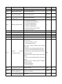
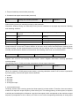
3. Dedicated Parameters
Parameter
Designation
Range
Default
Attr.
1
×
0
△
1.00
△
2
△
0: Invalid
Tension
F6-00
control
model
selection
1: Torque control mode
2: Speed control mode
3:Torque closed-loop control mode (reserved)
4: Constant linear speed control mode (reserved)
F6-01
F6-02
Winding
and
rewinding
0: Winding
selection
1: Rewinding
Register ratio
0.01~100.00
0: Invalid
F6-03
Linear
selection
speed
input
1: AI1 input
2: AI2 input
3: AI3 input
4: X7/DI pulse input
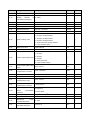
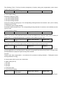
Parameter
Designation
Range
Default
Attr.
5: communication input
F6-04
Maximum linear speed
0.1m/min~6000.0m/min
F6-05
Minimum linear speed
0.1m/min~6000.0m/min
F6-06
Current
linear
speed
displayed value
0.1m/min~6000.0m/min
1000.0m/
min
200.0m/m
in
△
△
0.0m/min
△
0
△
500.0mm
△
0: Calculated by linear speed
1:Calculatedby thickness added up
2: AI1 input winding diameter
F6-07
Winding calculation mode
3: AI2 input winding diameter
4: AI3 input winding diameter
5: X7/DI pulse input winding diameter
6: Automatic calculation
F6-08
Maximum winding diameter
0.1mm~5000.0mm
F6-09
Minimum winding diameter
0.1mm~5000.0mm
F6-10
Initial winding diameter 1
0.1mm~5000.0mm
F6-11
Initial winding diameter 2
0.1mm~5000.0mm
100.0mm
△
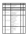
F6-12
Initial winding diameter 3
0.1mm~5000.0mm
100.0mm
△
1000
×
7.000s
△
0.0mm/s
△
1
×
100.0mm
100.0mm
△
△
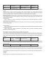
Units place: winding diameter reset selection
during running
0: Cannot reset when running
1: Can reset when running
Tens place: winding diameter reset selection
when stop
0: Remain current winding diameter when stop
1: Restore to initial winding diameter when stop
F6-13
Winding
diameter
calculation selection
Hundreds place: winding diameter reset selection
when power failure
0: Remain current winding diameter when power
failure
1: Restore to initial winding diameter when power
failure
Thousands place: winding diameter calculation
direction selection
0: Reverse allowable
1: Reverse forbidden
F6-14
F6-15
F6-16
Winding
diameter
calculation filter time
0.000s~60.000s
Amplitude limit of winding
0.0mm/s ~20.0mm/s
diameter change rate
0.0mm/s is unlimited
Number of pulses per lap
(when the winding diameter
0~65535
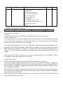
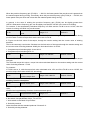
Parameter
Designation
Range
Default
Attr.
is calculated by thickness)
Laps per layer (when the
F6-17
winding
diameter
is
0~10000
1
×
calculated by thickness)
F6-18
Material thickness 0
0.01mm ~100.00mm
0.01mm
△
F6-19
Material thickness 1
0.01mm ~100.00mm
0.01mm
△
F6-20
Material thickness 2
0.01mm ~100.00mm
0.01mm
△
F6-21
Material thickness 3
0.01mm ~100.00mm
0.01mm
△
F6-22
Current winding diameter
0.1mm ~5000.0mm
0.0mm
△
0
×
0: F6-25 digital setting
1: AI1 input winding diameter
F6-23
2: AI2 input winding diameter
Tension setting mode
3: AI3 input winding diameter
4: X7/DI pulse input winding diameter
5: communication setting
F6-24
Maximum tension
0.0N~6553.5N
0.0N
△
F6-25
Tension digital setting value
0.0N~6553.5N
0.0N
△
0: F6-27 digital setting
1: AI1 input
F6-26
Tension taper setting mode
2: AI2 input
0
3: AI3 input
△
4: X7/DI pulse input
5: communication setting
F6-27
F6-28
Tension taper digital setting
value
Tension
taper
compensation correction
0.0%~100.0%
0.0%
0mm ~65535mm
0mm
△
△
F6-29
Zero-speed tension boost
0.0%~200.0%
0.0%
△
F6-30
Zero-speed threshold value
0.0%~100.0%
0.0%
△
0.0%~100.0%
0.0%
△
-50.0%~50.0%
0.0%
△
0
×
0
△
F6-31
F6-32
Sliding
friction
compensation torque
High speed sliding friction
compensation correction
Basis of high speed sliding
F6-33
friction
compensation
correction
0: frequency
0: linear speed
3
3
F6-34
Material density
0kg/m ~65535 kg/m
F6-35
Material width
0mm ~65535mm
0
△
0~1000
0
△
0.0s~10.0s
2.0s
×
F6-36
F6-37
Mechanical
inertia
compensation factor
Pre-drive winding diameter
calculation delay time
Parameter
Designation
Range
F6-38
Pre-drive frequency gain
0%~200.0%
Default
Attr.
100.0
△
0
△
0.0~200.0%
100.0%
△
0.0~200.0%
100.0%
△
0.0~200.0%
50.0%
△
3
×
000F
△
000F
△
0: Calculate torque limit value by tension setting
F6-39
Pre-drive torque limit mode
and current winding diameter
1: torque limit by d2-12, d2-13
2: torque limit by F6-41
F6-40
F6-41
F6-42
Pre-drive torque limit gain
Pre-drive torque limit digital
setting
Tension boost value
0: No switch, determined by parameters Kp1, Ti1
and Td1.
1: Auto switch on the basis of input offset
F0-14
PID parameter switch
2: Switched by terminal
3: Switched by winding diameter
4: Switched by linear speed
5: Switched by frequency
0: Display disabled; display enabled
Units place:
BIT0: running linear speed (m/min)
BIT1: Setting linear speed (m/min)
BIT2: Input terminal state
BIT3: Output terminal state
Tens place:
L1-01
LED
display
parameter
setting 2 on running status
BIT0: Closed-loop setting (%)
BIT1: Closed-loop feedback (%)
BIT2: Setting length (m)
BIT3: Actual length (m)
Hundreds place:
BIT0: Setting torque (%)
BIT1: Current winding diameter (0.1mm)
BIT2: Reserved
BIT3: Reserved
Thousands place: Reserved
0: Display disabled; display enabled
Unit’s place:
BIT0: Setting frequency (Hz)
BIT1: Busbar voltage (V)
L1-02
LED
display
parameter
setting on stop status
BIT2: Input terminal state
BIT3: Output terminal state
Tens place:
BIT0: AI1 (V)
BIT1: AI2 (V)
BIT2: AI3 (V)
Parameter
Designation
Range
Default
Attr.
BIT3: Reserved
Hundreds place:
BIT0: Closed-loop setting (%)
BIT1: Closed-loop feedback (%)
BIT2: Setting length (m)
BIT3: Actual length (m)
Thousands place:
BIT0: Setting linear speed (m/min)
BIT1: Current winding diameter (0.1mm)
BIT2: External count value
BIT3: DI
4. Dedicated Parameter Specifications
F6-00
Tension control model selection
Range: 0~4
Default: 1
Select tension control mode.
0: Invalid
Tension control invalid. Drives are the same as GK800 high performance AC motor drives.
1: Torque control mode
Tension detection device and tension feedback signals are unnecessary. The drive automatically calculates
current torque setting value basing on externally setting tension and current winding diameter, and performs
torque control, so as to control the tension of materials.
The control mode requires the drive to run in the vector control mode, and in high-demanding tension control
applications, the motor speed feedback encoder needs to be installed to perform closed-loop vector control.
Motor parameters (for details, see d0 group, or d3 group), vector control parameters (for details, see d2
group, or d4 group), and encoder parameters (for details, please see d6 group) are required to be set
correctly.
After F6-00 is set to 1, there is no need to set 1 in d2-00 or d5-00 (speed/torque control selection). The drive
automatically runs according to the torque control mode.
2: Speed control mode
Tension or position detection device are required (tension oscillating bar or floating roll).
The tension or position feedback signals can be sent to the drive to perform PID regulation, to stabilize the
feedback position in PID setting value, so as to ensure constant tension of the material. However, the tension
force is not always regulated by changing PID setting value, but by changing the balance weight of tension
bar or floating roll to regulate.
When running under tension control of this mode, there is no need to set frequency setting mode in b0 group,
but to correctly set linear speed input channel, so as to obtain correct linear speed signal. PID regulation
parameters can be set in F0 group.
When running under tension control of this mode the drive can work under V/F control, sensor-less vector
control, and closed-loop vector control
3: Torque closed-loop control mode (reserved)
4: Constant linear speed control mode (reserved)
F6-01
Winding and rewinding selection
Range: 0~1
Default: 0
Select winding running or rewinding running by this parameter.
Meanwhile, winding running and rewinding running can be switched over by digital input terminal “Winding
and rewinding selection”.
F6-01
Winding
terminal
and
rewinding
selection
Winding and rewinding status
0
OFF
winding
0
ON
rewinding
1
OFF
rewinding
1
ON
winding
Whether winding or rewinding, the moving direction when material is pulled tightly is considered as the
forward direction of the motor. Tension direction is the same as the motor forward direction. Namely, when
winding normally, and the tension direction is forward, then the winding motor runs forward. When rewinding
normally, and the tension direction is forward then the rewinding motor runs in a reverse direction.
F6-02
Register ratio
Range: 0.01~100.00
Default: 1.00
Register ratio must be set correctly during tension control. Register ratio=motor revolving speed/reel
revolving speed.
The following F6-03~F6-06 are function descriptions of linear speed calculation.
F6-03
Linear
speed
selection
input
Range: 0~5
Default: 2
When 2 is selected in F6-00 (speed control mode), or winding calculation mode F6-07 is set as 0 (calculated
by linear speed), correct linear speed must be obtained.
0: Invalid
1: AI1 input
2: AI2 input
3: AI3 input
4: X7/DI pulse input
5: communication input
Generally, traction motor revolving speed and linear speed is in linear relation. Therefore, the most common
method is to output the output frequency of the drive by AO. This analog quantity, as linear speed, is inputted
to winding and rewinding drive. Moreover, input the linear speed, which corresponds to the maximum output
frequency (corresponds to 10V or 20mA), to F6-04 so as to finish corresponding relationship of analog input
and linear speed.
When performing tension control (F6-00 selected as 2) under speed control mode, there is no need to set
frequency setting mode in b0 group. After setting this parameter correctly, the drive will calculate setting
frequency, according to the input linear speed and calculated winding diameter, and it will overlap PID
calculation output as the final frequency setting value of winding and rewinding drive. PID regulation
parameters are set in F0 group.
F6-04
Maximum linear speed
Range:
0.1m/min~6000.0m/min
Default:
1000.0m/min
When 1~4 is selected in F6-03, the linear speed corresponding to analog input maximum value (10V or 20mA)
or pulse input maximum value (50kHz) needs to be set. This linear speed is the maximum linear speed.
F6-05
Minimum linear speed
Range:
0.1m/min~6000.0m/min
Default:
200.0m/min
When the linear speed detected is smaller than this setting value, winding diameter calculation is not
performed, in case of causing major calculation error.
F6-06
Current linear
displayed value
speed
Range:
0.1m/min~6000.0m/min
Default:
0.0m/min
Display current running linear speed.
The following F6-07~F6-22 are function descriptions of winding diameter calculation.
F6-07
Winding
mode
calculation
Range: 0 ~6
Default: 0
Regardless torque control mode or speed control mode, when performing tension control of winding and
rewinding, current winding diameter needs to be correctly calculated. Winding diameter can be calculated via
the following modes.
0: Calculated by linear speed
The most common is winding calculation mode. Winding diameter is calculated by inputting linear speed and
running frequency of the winding and rewinding drive. At this moment, parameter F6-08~F6-15 needs to be
set correctly. The winding diameter calculation is shown in F6-22.
1: Calculated by thickness added up
Calculate winding diameter by material thickness added up, and need to input lap counting signal. At this
moment, parameter F6-16~F6-21 need to be set correctly. Winding diameter calculation result is shown in
F6-22.
2: AI1 input winding diameter
3: AI2 input winding diameter
4: AI3 input winding diameter
5: X7/DI pulse input winding diameter
When detecting winding diameter by winding diameter detection sensor, select input channel of the winding
diameter detection signal.
6: Automatic calculation
This is realized by internal automatic calculation and used to applications where winding diameter precision
and tension control precision are not so high.
F6-08
Maximum
diameter
winding
Range: 0.1mm ~5000.0mm
Default:
500.0mm
When 2 to 5 is selected in F6-07, the corresponding winding diameter of maximum value (10V or 20mA) of
analog input or pulse input of maximum value (50KHZ), is the maximum winding diameter.
Maximum winding diameter is also used for maximum amplitude during winding diameter calculation.
When not selecting “Initial winding diameter selection” terminal function, if reset winding diameter of the
rewinding drive, then the initial winding diameter will be F6-08 setting value after reset.
F6-09
Minimum
diameter
winding
Range: 0.1mm ~5000.0mm
Default:
100.0mm
Minimum winding diameter is also used for minimum amplitude during winding diameter calculation.
When not selecting “Initial winding diameter selection” terminal function, if reset winding diameter of the
winding drive, then the initial winding diameter will be F6-09 setting value after reset.
F6-10
Initial winding diameter 1
Range: 0.1mm ~5000.0mm
Default:
100.0mm
F6-11
Initial winding diameter 2
Range: 0.1mm ~5000.0mm
Default:
100.0mm
F6-12
Initial winding diameter 3
Range: 0.1mm ~5000.0mm
Default:
100.0mm
Set the initial winding diameter of winding and rewinding, by using digital input “Initial winding diameter
selection 1” and terminal “Initial winding diameter selection 2” terminal, as shown in the following table. When
digital input “Winding diameter reset” terminal is enabled, the winding diameter resets according to the initial
winding diameter as shown in the following table.
Initial
winding
selection 2
diameter
Initial
winding
selection 1
diameter
Initial winding diameter
OFF
OFF
F6-08 ( when rewinding)
F6-09 ( when winding)
OFF
ON
F6-10
ON
OFF
F6-11
ON
ON
F6-12
F6-13
Winding
diameter
calculation selection
Range: 0000~1111
Units place: Winding diameter reset selection when running
0: Cannot reset when running
1: Can reset when running
Tens place: winding diameter reset selection when stopping
0: Remain current winding diameter when stopping
1: Restore to initial winding diameter when stopping
Hundreds place: Winding diameter reset selection when power failure
0: Remain current winding diameter when power failure
1: Remain initial winding diameter when power failure
Thousands place: winding diameter calculation direction selection
Default: 1000
0: Reverse allowable
1: Reverse forbidden
F6-14
Winding
diameter
calculation filter time
Range: 0.000s~60.000s
Default: 7.000s
Range:
0.0mm/s
~20.0mm/s
0.0mm/s is no limit
Default: 0.0mm/s
Set filter time of winding diameter calculation.
F6-15
Amplitude
winding
change rate
limit
of
diameter
Limit the change rate of calculated winding diameter. Defined as: the winding diameter change at every
second is no more than this setting value. If set as 0.0, it means that rate amplitude limit does not perform.
When 1 is selected in F6-07 (calculate winding diameter by thickness), F6-16~F6-21 needs to be set.
F6-16
Number of pulses per lap
(When calculating winding
diameter by thickness)
Range: 0~65535
Default: 1
It refers to the number of pulse generated by digital input “Lap counting signal” when the reel revolves a lap.
F6-17
Laps per layer
(When
calculating
winding diameter by
thickness)
Range: 0~10000
Default: 1
This is generally used for wire material. Defined as: the material reels one full layer, when the reel revolves
the set laps as set in F6-17.
F6-18
Material thickness 0
Range: 0.01mm~100.00mm
Default: 0.01mm
F6-19
Material thickness 1
Range: 0.01mm~100.00mm
Default: 0.01mm
F6-20
Material thickness 2
Range: 0.01mm~100.00mm
Default: 0.01mm
F6-21
Material thickness 3
Range: 0.01mm~100.00mm
Default: 0.01mm
Select the thickness of material. The winding diameter adds once according to the material thickness when
the material rolls one full lap.
Material
selection 2
Material thickness selection 1
Material thickness
OFF
OFF
F6-18
OFF
ON
F6-19
ON
OFF
F6-20
ON
ON
F6-21
F6-22
thickness
Current
diameter
winding
Range: 0.01mm~100.00mm
—
No matter what kind of winding calculation mode is, the final calculated winding diameter displays on this
parameter, which can be changed online manually.
The following F6-23~F6-36 are function descriptions of tension setting and compensation under torque
control mode (F6-00 is set as 1).
F6-23
Tension setting mode
Range: 0~5
Default: 0
0: F6-25 digital setting
Set tension setting by F6-25.
1: AI1 input winding diameter
2: AI2 input winding diameter
3: AI3 input winding diameter
Set tension setting by analog input. The corresponding winding diameter for maximum value (10V or 20mA)
of analog input is F6-24.
4: X7/DI pulse input winding diameter
Set tension setting by pulse input. The corresponding winding diameter for maximum value (50kHz) of pulse
input is F6-24.
5: communication setting
F6-24
Maximum tension
Range: 0.0N~6553.5N
Default: 0.0N
When 1~4 is set in F6-23, maximum tension must be set. Defined as: maximum value (10V or 20mA) of
analog input, or corresponding diameter for maximum value (50kHz) of pulse input.
F6-25
Digital setting value for
tension
Range: 0.0N~6553.5N
Default: 0.0N
When the F6-23 is set to 0, the digital setting value for tension can be set through F6-25.
F6-26
Tension
mode
taper
setting
Range: 0~5
Default: 0
F6-23~F6-25: the taper compensation parameters, which are applicable to winding control only. In some
winding applications, the winding tension is required to be gradually decreased along with the increase of the
winding diameter for purpose of good curling of the material.
Formula:
Tension value after compensation = set tension*{1-K*[1-(minimum winding diameter + F6-28)/(the current
winding diameter+F6-28)]}
K: tension taper, which can be set via the below:
0: digital setting (F6-27)
1: AI1 input
2: AI2 input
3: AI3 input
4: X7/DI pulse input
5: communication setting
F6-27
Digital setting value of
tension taper
Range: 0.0%~100.0%
Default: 0.0%
When the tension taper setting mode F6-26 is set to 0, this parameter value will be the value of tension taper.
F6-28
Tension
taper
compensation correction
Range: 0mm~65535mm
Default: 0mm
Refer to the formula of taper compensation as abovementioned in F6-26.
The higher the compensation correction value, the lower the tension droop rate while the winding diameter
increases.
F6-29
Zero-speed
boost
tension
F6-30
Zero-speed threshold
Range: 0.0%~200.0%
Default: 0.0%
Range: 0.0%~100.0%
Default: 0.0%
F6-29: in order to overcome the static friction force during booting up, a proper tension boost value shall be
set. It indicates the percentage that the tension value makes up of the maximum tension value. Increase the
F6-29 setting value properly, in case the tension is set in a low value that may result in difficulty during
booting up.
F6-30: the inverter is running under zero-speed condition, when the running speed of the inverter is lower
than zero-speed threshold as set in F6-30. The zero-speed value (F6-30) indicates the percentage that the
frequency makes up of the maximum frequency value.
F6-31
Sliding
friction
compensation torque
Range: 0.0%~100.0%
Default: 0.0%
F6-32
High
speed
sliding
friction
compensation
correction
Range: -50.0%~50.0%
Default: 0.0%
F6-33
Basis of high speed
sliding
friction
compensation correction
Range: 0~1
Default: 0
F6-31: due to the sliding friction the actual tension is less than the setting value, especially when the winding
diameter is small or the tension is set to a small value. A proper setting of sliding friction compensation torque
is an effective solution.
F6-32: when the F6-32 is set at 0.0%, the sliding friction compensation is based on the setting value of F6-31
regardless of the speed. However, sliding friction may vary for some systems when speed changes.
A proper correction value set via F6-32 assists to enable the material tension to stay constant. When the
F6-32 setting value is: <0%, the high speed sliding friction is less than the low speed sliding friction value.
Conversely, when the F6-32 setting value is: >0%, the high speed sliding friction is greater than the low
speed friction sliding value
For F6-31 and F6-32, the setting value indicates the percentage that the compensation makes up of the rated
torque.
F6-33 indicates the identifying basis of the high/low speed.
0: identify via the running frequency of the winding and rewinding inverter.
1: identify via the linear speed.
F6-34
Material density
Range:
0kg/m3~65535kg/m3
Default: 0kg/m3
F6-35
Material width
Range: 0mm~65535mm
Default: 0mm
F6-36
Mechanical
inertia
compensation factor
Range: 0~1000
Default: 0
F6-34~F6-36: inertia compensation. Inertia is mainly comprised of two types: material inertial and mechanical
inertial.
Material inertial: is much in line with the density, width, winding diameter, min. winding diameter (winding
diameter of empty winding) of the material. Basing on these the inverter is able to figure out the required
inertial compensation torque. The density and width of the material need to be set properly.
Mechanical inertia: includes inertia of winding and rewinding motor rotor, drive system inertia, and reel
inertia. Mechanical inertia is irrelevant with the material, thus when empty winding, the F6-36 setting value
can be modified as below:
During winding:
When it speeds up, properly increase the F6-36 setting value if the tension decreases. Whereas,
decrease the F6-36 setting value.
When it slows down, properly increase the F6-36 setting value if the tension increases. Whereas, decrease
the F6-36 setting value.
During rewinding:
When it speeds up, properly increase the F6-36 setting value if the tension increases. Whereas, decrease
the F6-36 setting value.
When it slows down, properly increase the F6-36 setting value if the tension decreases. Whereas,
decrease the F6-36 setting value.
F6-37~F6-41: Pre-drive function during automatic roll alternation
In the case of reel alternation during the running, it is necessary to rotate the winding and rewinding reel in
advance, and the linear speed of rotating shall be consistent with the linear speed of material. The pre-drive
status of the inverter starts, after it receives the “Run Command” and the digital input “pre-drive terminal” is
enabled.
F6-37
Pre-drive
diameter
delay time
winding
calculation
Range: 0.0s~10.0s
Default: 2.0s
After the pre-drive is ended, there is a delay time which is defined by F6-37 before the winding diameter
calculation starts up. This helps to avoid the winding diameter calculation fluctuation at the instant of the
pre-drive ending.
F6-38
Pre-drive frequency gain
Range: 0%~200.0%
Default: 100.0%
The inverter automatically calculate the Running Frequency in terms of linear speed and winding diameter
during pre-drive, so as to keep the linear speed of pre-drive reel in consistency with the material linear speed.
The automatically calculated Running Frequency can be properly corrected through pre-setting the pre-drive
frequency.
Formula:
Revised frequency= automatically calculated Running Frequency * F6-38 set value
When the pre-drive frequency gain (F6-38) is: ﹥100.0%, the linear speed of the pre-drive reel is greater than
the material speed during running. Conversely, when the pre-drive frequency gain (F6-38) is: <100.0%, the
linear speed of the pre-drive reel is less than the material speed during running.
In general, in the case of winding the pre-drive frequency gain (F6-38) can be slightly greater than
100.0% .Whereas the frequency gain can be slightly less than the 100.0% in the case of re-winding.
For instance, if the automatically calculated frequency is 5.00Hz and the F6-38 is set at 110.0%, then the
inverter is running at 5.50Hz in a pre-drive state
F6-39
Pre-drive
mode
torque
limit
Range: 0~2
Default: 0
The output torque is required to be limited since the inverter is running in a speed control state during
pre-drive state. Pre-drive torque limit mode can be set via F6-39.
0: Figure out the limit value of the torque, through the tension setting and the current value of winding
diameter.
This is the commonly used mode. Calculate out the limit value of the torque through the tension setting and
the current value of winding diameter. Modify the limit value further via F6-40.
1: Complete torque limit through d2-12 and d2-13.
2: Complete torque limit through F6-41.
F6-40
Pre-drive
gain
torque
limit
Range: 0.0~200.0%
Default: 100.0%
When the F6-39 is set to: 0, the torque limit value figured out already can be corrected by setting this torque
limit gain.
The corrected torque limit value = torque limit value calculated based on the tension setting and the current
value of winding diameter * F6-40
For instance:
If F6-39 is set to: 0 , with the torque limit value calculated to be 10%, and if the F6-40 is set to 120.0%, the
pre-drive torque limit value will be 12% accordingly.
F6-41
Digital
setting
for
pre-drive torque limit
Range: 0.0%~200.0%
Default: 100.0%
When the F6-39 is set to: 2, the pre-drive torque limit value can be set by F6-41.
Auxiliary function description
F6-42
Tension boost value
Range: 0.0%~200.0%
Default: 10.0%
When the digital input terminal of “Tension boost” is enabled, the tension boost is based on the F6-42 setting
value.
Modified and supplementary functions of other parameter group:
F0-14
PID parameters switch
Range: 0~5
When F6-00 is set to 2, (Speed control mode), this parameter is valid.
0: No switch. Use parameters of Kp1, Ti1 and Td1
1: Auto switch on the basis of input offset
2: Switch by terminal
Quite the same with the standard products if choose 0~2.
3: Switch by winding diameter
Default: 3
When minimum winding diameter: use parameters of Kp1, Ti1 and Td1. When maximum winding diameter:
use parameters of Kp2, Ti2 and Td2. When between minimum and maximum winding diameter, the PID
parameter changes continuously.
4: Switch by linear speed
When the linear speed is 0: use parameters Kp1, Ti1 and Td1. When maximum linear speed: use parameters
of Kp2, Ti2 and Td2. When the linear speed is between 0 and maximum linear speed, the PID parameter
changes continuously.
5: Switch by frequency
When the frequency is 0: use parameters of Kp1, Ti1 and Td1. When maximum frequency: use parameters of
Kp2, Ti2 and Td2. When the frequency is between 0 and maximum frequency, the PID parameter changes
continuously.
Supplementary terminal functions:
C0-01
Function of terminal X1
C0-02
Function of terminal X2
C0-03
Function of terminal X3
C0-04
Function of terminal X4
C0-05
Function of terminal X5
C0-06
Function of terminal X6
C0-07
Function of terminal X7/D1
C0-08
Function of terminal
(digital enabled)
AI1
C0-09
Function of terminal
(digital enabled)
AI2
C0-10
Function of terminal
(digital enabled)
AI2
70: Tension control prohibited
71: Winding and rewinding
selection
72: Winding diameter reset
73: Initial winding diameter
selection 1
74: Initial winding diameter
selection 2
75: Winding diameter calculation
pause
76: Material thickness selection 1
77: Material thickness selection 2
78: Lap counting signal
79: Pre-drive enabled
80: Tension boost
Default: 0
Default: 0
Default: 0
Default: 0
Default: 0
Default: 0
Default: 0
Default: 0
Default: 0
Default: 0
70: Tension control prohibited
When this terminal is enabled, the tension control is prohibited. Which is equivalent to that the F6-00 is set to
0.
71: Winding and rewinding selection
Refer to F6-01 functions description, which enables a switch between winding and rewinding.
72: Winding diameter reset
The winding diameters need to be reset at the initial value in case of reel alternation.
73: Initial winding diameter selection 1
74: Initial winding diameter selection 2
Basing on the above terminal functions (73~74) different initial winding diameters can be choose /set, for
which please kindly refer to F6-10~F6-12.
75: Winding diameter calculation pause
The winding diameter calculation is paused when this terminal is enabled.
76: Material thickness selection 1
77: Material thickness selection 2
Material thickness can be set basing on the aforementioned terminal functions (76~77)
78: Lap counting signal
When the winding diameter is calculated by thickness added up, calculate the laps of the reel by this input
signal.
79: Pre-drive enabled
When this terminal is enabled, the pre-drive running mode is activated.
When this terminal is disabled, the inverter is running in tension control mode.
80: Tension boost
When this terminal is enabled, the tension boost can be started basing on the F6-42 setting value.
C3-00
AO1 output
selection
function
C3-01
AO2 output
selection
function
C3-02
Y2/DO output function
selection (When used as
DO )
18: Winding diameter output
2
1
2
18: Output winding diameter
Output winding diameter calculation. The maximum winding diameter is corresponding to the maximum
analog value (10V or 20mA), or the maximum pulse frequency (50kHz).
L1-01
LED display parameter
setting 2 on running
status
0: Display disabled; display enabled
Units place:
BIT0: running linear speed (m/min)
BIT1: Setting linear speed (m/min)
BIT2: Input terminal state
BIT3: Output terminal state
Tens place:
BIT0: Closed-loop setting (%)
BIT1: Closed-loop feedback (%)
BIT2: Setting length (m)
BIT3: Actual length (m)
Hundreds place:
BIT0: Setting torque (%)
Range: 0000~37FF
Default: 000F
BIT1: Current winding diameter (0.1mm)
BIT2: Reserved
BIT3: Reserved
Thousands place:
BIT0: Reserved
BIT1: Reserved
BIT2: Reserved
BIT3: Reserved
L1-02
LED display parameter
setting on stop status
Range: 0000~FF7F
Default: 000F
LED display parameters can be set, when inverter is in stopped state. Press the
for multiple parameters selection or display.
0: Display disabled; display enabled
Unit’s place:
BIT0: Setting frequency (Hz)
BIT1: Busbar voltage (V)
BIT2: Input terminal state
BIT3: Output terminal state
Tens place:
BIT0: AI1 (V)
BIT1: AI2 (V)
BIT2: AI3 (V)
BIT3: Reserved
Hundreds place:
BIT0: Closed-loop setting (%)
BIT1: Closed-loop feedback (%)
BIT2: Setting length (m)
BIT3: Actual length (m)
Thousands place:
BIT0: Setting linear speed (m/min)
BIT1: Current winding diameter (0.1mm)
BIT2: External count value
BIT3: DI
button on the keyboard