1
Appendix
Technical Publication
AP-0015R2
Quick Installation Guide
for TXR Generators
HF Series Generators
HF Series Generators
Appendix -- Quick Installation Guide for TXR Generators
REVISION HISTORY
REVISION
DATE
REASON FOR CHANGE
0
JAN 7, 2004
1
OCT 16, 2007
General Update & Improvement
2
AGO 06, 2009
Dip--Switch configuration of HT Controller
First edition
This Document is the English original version, edited and supplied by the manufacturer.
The Revision state of this Document is indicated in the code number shown at the bottom of this page.
ADVISORY SYMBOLS
The following advisory symbols will be used throughout this manual. Their
application and meaning are described below.
DANGERS ADVISE OF CONDITIONS OR SITUATIONS THAT
IF NOT HEEDED OR AVOIDED WILL CAUSE SERIOUS
PERSONAL INJURY OR DEATH.
ADVISE OF CONDITIONS OR SITUATIONS THAT IF NOT
HEEDED OR AVOIDED COULD CAUSE SERIOUS PERSONAL
INJURY, OR CATASTROPHIC DAMAGE OF EQUIPMENT OR
DATA.
Advise of conditions or situations that if not heeded or
avoided could cause personal injury or damage to equipment
or data.
Note
AP-0015R2
.
Alert readers on pertinent facts and conditions. Notes represent
information that is important to know but which do not necessarily
relate to possible injury or damage to equipment.
HF Series Generators
Appendix -- Quick Installation Guide for TXR Generators
TABLE OF CONTENTS
Section
Page
1
INSTALLATION . . . . . . . . . . . . . . . . . . . . . . . . . . . . . . . . . . . . . . . . . . . . . . . . . . . . . . . . . .
1
2
CONFIGURATION . . . . . . . . . . . . . . . . . . . . . . . . . . . . . . . . . . . . . . . . . . . . . . . . . . . . . . .
9
2.1
Proper Dip Switch Selections on the ATP Console CPU Board . . . . . . . . . . . .
9
2.2
Configuring the Workstations . . . . . . . . . . . . . . . . . . . . . . . . . . . . . . . . . . . . . . . . .
10
2.3
Configuring the Tube Type . . . . . . . . . . . . . . . . . . . . . . . . . . . . . . . . . . . . . . . . . . .
12
CALIBRATION . . . . . . . . . . . . . . . . . . . . . . . . . . . . . . . . . . . . . . . . . . . . . . . . . . . . . . . . . .
15
3.1
Previous Tasks . . . . . . . . . . . . . . . . . . . . . . . . . . . . . . . . . . . . . . . . . . . . . . . . . . . . .
15
3.2
Digital kV Loop Open . . . . . . . . . . . . . . . . . . . . . . . . . . . . . . . . . . . . . . . . . . . . . . . .
16
3.3
Digital mA Loop Closed . . . . . . . . . . . . . . . . . . . . . . . . . . . . . . . . . . . . . . . . . . . . . .
17
3.4
Auto-calibration of Digital mA Loop Open . . . . . . . . . . . . . . . . . . . . . . . . . . . . . .
17
3.5
Final Checks . . . . . . . . . . . . . . . . . . . . . . . . . . . . . . . . . . . . . . . . . . . . . . . . . . . . . . .
22
4
APR EDITING . . . . . . . . . . . . . . . . . . . . . . . . . . . . . . . . . . . . . . . . . . . . . . . . . . . . . . . . . . .
23
5
BUCKY INTERFACE CONNECTIONS .. . . . . . . . . . . . . . . . . . . . . . . . . . . . . . . . . . . . . . . . . 31
3
AP-0015R2
i
HF Series Generators
Appendix -- Quick Installation Guide for TXR Generators
ii
AP-0015R2
HF Series Generators
Appendix -- Quick Installation Guide for TXR Generators
SECTION 1
INSTALLATION
THIS DOCUMENT PROVIDES A STEP BY STEP GUIDE AND IS
NOT INTENDED TO TAKE THE PLACE OF THE SERVICE
MANUAL. AS STEPS ARE COMPLETED CHECK OFF THE
LIST TO THE LEFT OF EACH NUMBER OR PARAGRAPH.
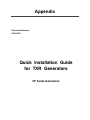
1.
Place the Power Module close to its permanent position. For easy
interconnection and calibration place the Generator Cabinet on a table
or pedestal; or mount it to the wall using the Wall Support provided.
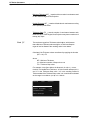
2.
Verify that wire marked “:” on Transformer 6T2 terminal strip is matched
to the incoming power. Identify the Generator type: Single--Phase,
Three--Phase or Battery Powered.
POWER SUPPLY LINE FOR SINGLE-PHASE OR BATTERY POWERED GENERATORS
Cable-: in Transformer 6T2
110 VAC or
Stand-Alone option
208 VAC
220 / 230 VAC
240 VAC
TB-3 or TB-8
TB-21
TB-4 or TB-5
TB-6 or TB-7
POWER SUPPLY LINE FOR THREE-PHASE GENERATORS
Cable-: in Transformer 6T2
220 / 230 / 240 VAC
400 VAC
415 VAC
440 VAC
480 VAC
TB-4 or TB-5
TB-8
TB-7
TB-9
TB-10
6T2 Terminal Strip
AP-0015R2
1
HF Series Generators
Appendix -- Quick Installation Guide for TXR Generators
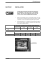
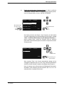
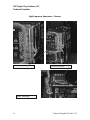
3.
THIS POINT ONLY APPLIES TO BATTERY POWERED GENERATORS.
a.
Open hinged door to access to Charger Module (Mod 1) by
removing the Allen screws.
b.
Verify that wire marked “:” is connected to Transformer 2T1
terminal strip -- 110 (for 110 VAC).
c.
Remove plastic covers over Charger Board and Line Monitor
Board.
d.
Plug J1 into the Charger Board, it is unplugged at the factory for
safety.
e.
Verify Jumper SW1 connection between SW1--5 and SW1--4
(110 VAC).
f.
Re-install plastic covers.
Line Monitor Board
Plastic Covers
Charger Board
J1
6T2 Terminal Strip
SW1
J1 Connection
J1
J1
T1
SW1
SW1 Jumper
T1 Terminal Strip
2
AP-0015R2
HF Series Generators
Appendix -- Quick Installation Guide for TXR Generators
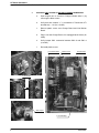
4.
TXR products require 24 VAC for locks. At top of the Generator cabinet
a 24 VAC Distribution Board has been added to connect these locks.
24 VAC
Distribution
Board
3
4
5
6
7
8
24VAC 0VAC +24VDC 0VDC +24VDC 0VDC
Terminals 1 and 2 are in coming 24VAC
Collimator is connected to terminals 3 and 4
5.
AP-0015R2
Remove Allen screws that secure hinged door on MOD3 side.
3
HF Series Generators
Appendix -- Quick Installation Guide for TXR Generators
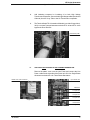
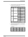
6.
The Terminal Strip 4TS2 is located on Module 4 (back of Module 3) of the
hinged door. Connect the X-ray Tube Rotor wiring as follows:
WIRE FROM X-RAY TUBE
CONNECTION IN 4TS2
BLACK
4TS2--1
RED
4TS2--2
WHITE
4TS2--3
THERMAL
4TS2--4
THERMAL
4TS2--5
GROUND *
4TS2--6
* If X-ray Tube have not a shielded Ground wire, terminal 4TS2--6 is not used.
4TS2 Terminal Strip
7.
Connection of
Serial Cable
at Console
4
Carefully connect the J5 side of the Serial cable to the Console and then
route the Handswitch wire. Connect the J1 side of the Serial cable from
the Console to the Generator Cabinet.
Connection of Serial Cable
at Generator Cabinet
(located on upper back)
AP-0015R2
HF Series Generators
Appendix -- Quick Installation Guide for TXR Generators
8.
Add insulating compound or insulating oil to both High Voltage
Transformer receptacles. Connect both High Voltage cables (Anode and
Cathode) from the X-ray Tube to the HV Transformer receptacles.
9.
The Terminal Strip 3TS1 is located on Module 3 (out-side of hinged door).
Verify or connect a jumper between terminals 3TS1--22 and 3TS1--23 to
bypass the Door Interlock.
Terminal Strip 3TS1
10.
THIS POINT ONLY APPLIES TO LINE POWERED GENERATORS.
Remove the plastic cover over the Line Fuses and connect the Line
Power cables to the right side of the Fuses at L1 & L2 for Single Phase
Generators and also at L3 for Three Phase Generators.
Input Transf. 6T2
Plastic Cover over Line Fuses
GND Stud
L1 Input Line
L2 Input Line
L3 Input Line
Single Phase
Neutral Stud
Three Phase
AP-0015R2
(optional)
5
HF Series Generators
Appendix -- Quick Installation Guide for TXR Generators
11.
THIS POINT ONLY APPLIES TO BATTERY POWERED GENERATORS.
a.
Connector 6J10 on the right side of Generator Cabinet (Module 6)
is unplugged for safety during transport. Plug in it.
Connector 6J10
b.
Connect the Line Power cable to Line Connector (wire-1 to left,
wire-2 to middle, ground wire to right). These connections are
color coded.
Line Connector
Circuit Breaker
6
AP-0015R2
HF Series Generators
Appendix -- Quick Installation Guide for TXR Generators
c.
Turn On the Circuit Breaker. Visually check that all green lights and
LED DS1 are lit on the Charger Board.
LED DS1
Connector J1
Row of Green LEDs
Charger Board
d.
Visually verify that LED DL1 (yellow) is flashing on the Line
Monitor Board (2A3). The MAX and MIN LEDs (red) on the Line
Monitor Board check the line coming in, neither should be on.
Potentiometer POT1 is factory adjusted. If MAX or MIN LED is
ON, first check that Mains Voltage is according to specifications on
page 1 of this guide. If Mains Voltage is correct, adjust POT1 (CW
up, CCW lower) measuring between TP-1 and TP-2 on Line
Monitor Board. Potentiometer adjustment should be:
Potentiometer =
Potentiometer
Line Monitor Board
AP-0015R2
Mains Voltage
Nominal Voltage
x 2.5
Max and Min Lights
Check Light Flashing
7
HF Series Generators
Appendix -- Quick Installation Guide for TXR Generators
This page intentionally left blank.
8
AP-0015R2
HF Series Generators
Appendix -- Quick Installation Guide for TXR Generators
SECTION 2
2.1
CONFIGURATION
PROPER DIP SWITCH SELECTIONS ON THE ATP CONSOLE CPU BOARD
Note
.
The ATP Console CPU Board is located on Module 4 side of the
Hinged Door.
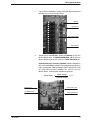
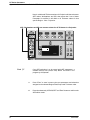
1.
Locate Switches #1, #2 and #3 on the ATP Console CPU Board from the
illustration.
G
Switch #1 contains four Dip Switches.
G
Switch #2 contains four Dip Switches.
G
Switch #3 contains eight Dip Switches (for factory use).
Swicth #2
Swicth #3
Swicth #1
ATP Console Board
2.
AP-0015R2
Configuration of Switch #1.
G
For use with 60 Hertz Line Supply: All four Dip Switches must
be placed in the down (OFF) position.
G
For use with 50 Hertz Line Supply: The first Dip Switch must be
placed in the up (ON) position. The second, third and fourth Dip
Switches must be placed in the down (OFF) position.
3.
Configuration of Switch #2. The first, third and fourth Dip Switches
must be placed in the up (ON) position. The second Dip Switch must be
placed in the down (OFF) position.
4.
Configuration of Switch #3. All eight Dip Switches must be placed in
the down (OFF) position.
9
HF Series Generators
Appendix -- Quick Installation Guide for TXR Generators
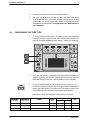
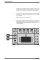
2.2
CONFIGURING THE WORKSTATIONS
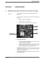
1.
With the Generator OFF, make sure Dip 3 of Switch #2 on the ATP
Console CPU Board (Module 4 side) is placed in the closed (ON) position
(Service Mode enabled).
2.
Turn ON the Line Power and then the Console power. Wait for the self
testing to finish, then enter in configuration mode by maintaining pressed
Power ON, “200” and “800” simultaneously for at least two seconds until
all of the workstations push-buttons are illuminated.
3.
Results you should see:
A display of numbers will be visible on the kVp, mAs, mA and time
displays. The visible numbers will either be 0, 1, 2, etc.
The Console is equipped to operate in five different modes
(workstations). The three push-buttons at the upper-left provide a way to
program for different operations. See the following tables for proper
selections.
10
AP-0015R2
HF Series Generators
Appendix -- Quick Installation Guide for TXR Generators
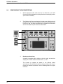
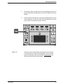
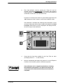
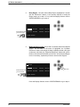
4.
Select the first workstation to be configured (Bucky 1, Bucky 2, No Bucky)
by pressing the respective push-button, only this push-button blinks and
the console shows one of the following values:
DISPLAY
1st Value
2nd Value
3rd Value
FUNCTION
VALUE
SELECT THE TUBE
SELECT THE DEVICE
(WORKING MODE)
SELECT THE ION
CHAMBERS BEING
USED (ONLY WITH AEC)
DESCRIPTION
0
No-configured workstation
1
Tube-1
2
Tube-2
0
Direct (No Bucky)
1
Bucky-1
2
Bucky-2
3
Standard Tomo *1)
4
Standard RF
0
No AEC
1
Ion Chamber-1
2
Ion Chamber-2
3
Ion Chamber-3
4
Ion Chamber-4
Notes.-- Some values may not be configurable, depending on Generator model.
*1) Only when the Tomo is controlled by the Generator.
5.
Set the new value by pressing the Density “+” or “--” buttons located at
the bottom left corner of the Operator Console. When the first value is “0”,
the second and third value are “0”.
The following table is an example of a 2 tube System with 2 Buckys and
no Ion Chambers.
AP-0015R2
B tt
Button
kV
kVp
mAs
A
mA
A
Ti
Time
Bucky 1
1
(tube 1)
1
(Bucky 1)
0
(no Ion Chamber)
0
Bucky 2
2
(tube 2)
2
(Bucky 2)
0
(no Ion Chamber)
0
No Bucky
1
(tube 1)
0
(No Bucky)
0
(no Ion Chamber)
0
11
HF Series Generators
Appendix -- Quick Installation Guide for TXR Generators
2.3
6.
Continue Configuration for the remaining Workstations.
7.
Exit from configuration by pressing the “200” and “800” pushbuttons
down simultaneously for at least two seconds until you hear an audible
double beep. This sound signals that you have successfully saved the
workstations you had selected. Configuration of the Workstations is
now completed.
CONFIGURING THE TUBE TYPE
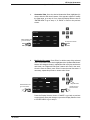
1.
To configure the X-ray Tube type, it is necessary to enter into Calibration
Mode by pressing the “200” and “800” push-buttons simultaneously. The
light of the selected workstation blinks (Bucky 1, Bucky 2 or No Bucky).
2.
Press the “mA Increase” push-button until you reach the maximum mA
capacity. Press the “mA Increase” push-button twice more to reach the
Extended Memory Code “E02”, that will appear on the mA Display.
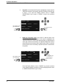
3.
In order to configure the X-ray Tube type and model, press the “+” or “--”
Density push-buttons until one of the Tube Type numbers listed below is
shown on the kVp Display. (The entire list of Tube Data is found in your
Service Manual on the last page of the Configuration Section).
Normally one of the following three Tube capacities is chosen:
TUBE NUMBER
(kVp Display)
TUBE CODE (ID)
(mAs Display)
001
139
003
004
12
POWER RATINGS
FOCAL
SPOT
LS (kW)
HS (kW)
TOSHIBA E7239X
1.0 / 2.0
22 / 45
--
133
140
TOSHIBA E7242X
0.6 / 1.5
18 / 49
--
187
090
TOSHIBA E7252X
0.6 / 1.2
15 / 42
26 / 73
300
MODEL
KHU
AP-0015R2
HF Series Generators
Appendix -- Quick Installation Guide for TXR Generators
Note
AP-0015R2
.
4.
Verify that the Tube code (ID) shown on the mAs Display is the same as
the tube code listed in the table above or in the Tube Table of the Service
Manual.
5.
Press the “Reset” Push-button to save and permanently store the X-ray
Tube configuration. You will once again hear an audible beep to confirm
that you have successfully saved your selection.
At this point, if your selected Bucky is still blinking, you are already
in Service Mode and ready for Autocalibration. If your selected
Bucky is not blinking, press “200” and “800” simultaneously for at
least two seconds to enter Service Mode.
13
HF Series Generators
Appendix -- Quick Installation Guide for TXR Generators
This page intentionally left blank.
14
AP-0015R2
HF Series Generators
Appendix -- Quick Installation Guide for TXR Generators
SECTION 3
3.1
CALIBRATION
PREVIOUS TASKS
Before calibration, keep in mind that:
1.
To calibrate and measure the kVp output, a Non-Invasive kVp Meter is
needed.
Place and center a Non-Invasive kVp Meter on the X-ray Tube output at
the required SID (refer to the Non-Invasive kVp Meter documentation).
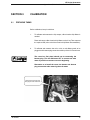
2.
To calibrate and measure the mA or mAs, a mAs Meter needs to be
plugged to the banana plug connection at the top of the HV Transformer.
The cross bar (link plate) should not be connecting the
banana plug. Turn the Generator OFF to connect the mAs
meter if you did not connect one at the beginning.
Remember to re-install the cross bar between the banana
plug connections after removing the mAs meter.
Remove the cross bar (link)
and plug the mAs meter here.
AP-0015R2
15
HF Series Generators
Appendix -- Quick Installation Guide for TXR Generators
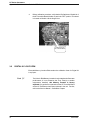
3.
Before calibration procedure, verify that the Dip Switches of Switch #2 of
the HT Controller Board (A3000--xx) are in the “OFF” position. This board
is located on Module 3 at the hinged door.
Switch #2 on the
HT Controller Board
3.2
DIGITAL KV LOOP OPEN
Extended Memory Location E06 contains the calibration factor for Digital kV
Loop Open.
Note
16
.
The Value in E06 Memory Location is only related to the Generator
performance (it is not related to the X-ray Tube(s) or another
components installed), this Memory Location is factory
adjusted. Only perform this procedure if the HT Controller Board
and/or HV Transformer have been replaced in the unit. For that,
refer to the Service Manual -- Calibration Chapter.
AP-0015R2
HF Series Generators
Appendix -- Quick Installation Guide for TXR Generators
3.3
DIGITAL mA LOOP CLOSED
Extended Memory Locations E03 and E05 contain the calibration factor for
Digital mA Loop Closed.
Note
3.4
.
Values in E03 and E05 Memory Locations are only related to the
Generator performance (they are not related to the X-ray Tube(s)
installed). These Memory Locations are factory adjusted. Only
perform this procedure if the HT Controller Board and/or HV
Transformer have been replaced in the unit. For that, refer to the
Service Manual -- Calibration Chapter.
AUTO-CALIBRATION OF DIGITAL mA LOOP OPEN
To achieve the most accurate calibration, this procedure has to be
automatically performed by the Generator (Auto-calibration).
The Calibration procedure should be manually performed only if
Auto-calibration is not possible. In this case, refer to the Service Manual
(Calibration Chapter -- Section “Manual Calibration of Digital mA Loop Open”).
Auto-calibration of the Filament Current Numbers is divided in two separated
procedures related to the mA stations configured for the Small or Large Focal
Spots. Start with the Small Focal Spot (first group) and continue with the Large
Focal Spot (second group).
EACH TIME THAT AUTO-CALIBRATION IS ACTIVATED IN A
mA STATION (OR IN “E01” MEMORY LOCATION), ALL THE
FILAMENT CURRENT NUMBERS OF THE SELECTED FOCAL
SPOT ARE AUTOMATICALLY SET TO “344”. SO A NEW
COMPLETE CALIBRATION OF THE FILAMENT CURRENT
NUMBERS FOR THIS FOCAL SPOT WILL BE REQUIRED.
AP-0015R2
17
HF Series Generators
Appendix -- Quick Installation Guide for TXR Generators
Auto-calibration starts with the minimum available mA station for the
selected Focal Spot at 50 kV and follows with the other combinations of
mA stations for the selected Focal Spot at 80 kV, 120 kV and 40 kV.
18
1.
For this procedure, set Dip Switch 4 of Switch #2 on the HT Controller
Board back in the “ON” position (Digital mA Loop Open / Filament
Current Constant).
1.
Select the “No Bucky” workstation (Direct).
2.
Enter calibration mode by pressing the “200” and “800” push-buttons
simultaneously and select one of the configured mA stations for the
Small Focal Spot (Light will be blinking for workstation selected if you
are in Service Mode).
AP-0015R2
HF Series Generators
Appendix -- Quick Installation Guide for TXR Generators
3.
Enter Auto-calibration mode by pressing the “Power On” and “kV
increase” push-buttons simultaneously for 2 seconds. After releasing
both push-buttons, code “222” will be flashing on the Console waiting for
confirmation to then enter Auto-calibration mode.
Press the “kV increase” and “Power On” push-buttons again until code
“222” disappears on the Console to confirm Auto-calibration mode.
Auto-calibration is activated after releasing both push-buttons. At this
moment, the Generator will check the mA stations available for the Small
Focal Spot. When 50 kV at 10 mA is displayed in the display windows,
the Unit is ready for Auto-calibration.
4.
Check that the Heat Units available for the X-ray Tube are 100%
(kV Display shows “H -- --” on the Console).
5.
Keep the Handswitch push-button fully pressed or use the Exposure
Controls on the Console to perform continuous exposures.
Auto-calibration can be stopped momentarily by releasing
the Handswitch push-button or the Exposure Controls. Do
not exit from Auto-calibration before the procedure has been
completed.
AP-0015R2
19
HF Series Generators
Appendix -- Quick Installation Guide for TXR Generators
If the Heat Units available for the X-ray Tube are less than 40%,
exposures are inhibited momentarily and code “111” will be flashed on the
Console accompanied by an alarm. In this case, release the Handswitch
or Exposure Controls to stop momentarily the Auto-calibration
procedure. The alarm will stop when the X-ray Tube begins to cool and
recovers the Heat Units capacity. Exposures can be performed again
even though code “111” is shown on the Console.
At this point, it is recommended to wait until the Heat Units available are
close to 80% of the X-ray Tube capacity without making any exposure.
The Generator will try to calibrate each kV / mA combination for ten (10)
attempts (maximum). If calibration is aborted (after ten attempts), code
“888” will flash on the Console until the “Power On” push-button is
pressed to exit Calibration. Calibration might also abort due to space
charge during calibration of the lowest kV at the highest mA stations for
the Focal Spot selected, so code “777” will be flashing on the Console
until the “Power On” push-button is pressed.
IF AUTO-CALIBRATION IS ABORTED (CODE “888” OR
“777”), CONTINUE AUTO-CALIBRATION FOR THE OTHER
FOCAL SPOT. CHECK AT THE END OF AUTO-CALIBRATION
WHICH KV / MA COMBINATIONS HAVE NOT BEEN
AUTO-CALIBRATED FOR EACH FOCAL SPOT (THESE
COMBINATIONS HAVE THE FILAMENT CURRENT NUMBER
SET TO “344”). MANUALLY CALIBRATE THESE KV / MA
COMBINATIONS AS EXPLAINED IN THE SERVICE MANUAL
(CALIBRATION CHAPTER -- “MANUAL CALIBRATION OF
DIGITAL mA LOOP OPEN”).
When Auto-calibration is successfully performed, code “999” will be
flashing on the Console until press the “Power On” push-button for 2
seconds to exit from Auto-calibration mode. The “999” code will
disappear when you have successfully exited Calibration.
6.
To calibrate the Large Focal Spot, select one of the configured mA
stations for the Large Focal Spot by pressing the mA “+” push-button.
Repeat steps 2.-- 5.
Before starting the exposures, it is recommended to wait until the Heat
Units available are closed to the 80% of the X-ray Tube capacity.
20
AP-0015R2
HF Series Generators
Appendix -- Quick Installation Guide for TXR Generators
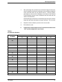
7.
After performing both procedures (for Small and Large Focal Spots),
select in calibration mode each combination of the available mA stations
at the kV break points (40, 50, 80 and 120 kV). Press the “Reset”
push-button to read on the kV Display the new value of the Filament
Current Number stored for each combination and write down the new
values in the Data Book.
Note that the highest mA station for Small Focal Spot may have numbers
larger than the lowest mA station for Large Focal Spot. This is normal.
8.
Repeat the above calibration process for the second tube.
9.
Exit calibration mode.
10.
Set Dip Switch 4 of Switch #2 on the HT Controller Board back in the
“OFF” position (Digital mA Loop Closed).
Table 3-1
mA Calibration Numbers
mA STATION
FILAMENT CURRENT NUMBERS AT kV BREAK POINT
40
50
80
120
10
12.5
16
20
25
32
40
50
64
80
100
125
160
200
250
320
400
500
640
800
Note.-- Some Generator models do not contain all the mA stations listed above.
AP-0015R2
21
HF Series Generators
Appendix -- Quick Installation Guide for TXR Generators
3.5
FINAL CHECKS
Verify that all Configuration and Calibration data have been properly stored in
memory.
1.
Enter in calibration mode and check that the values noted for the
“Filament Current Numbers” and “Extended Memory Locations” of the
Data Book are the same values displayed and stored in memory. Press
the “Reset” button to read the stored values.
2.
Exit from calibration mode and Service mode.
3.
Turn the Generator OFF and verify position of Dip Switches of Switch #2
on the HT Controller Board are:
4.
22
G
Dip Switch 2 in “Off” position (enables Filament and Rotor
Interlocks).
G
Dip Switch 4 in “Off” position (Digital mA Loop Closed).
Set Dip Switch 3 of Switch #2 on the ATP Console CPU Board in “Off”
position to place the Generator in normal operating mode.
AP-0015R2
HF Series Generators
Appendix -- Quick Installation Guide for TXR Generators
SECTION 4
APR EDITING
Any APR Technique may be modified to fit the operator requirements. It is
possible to change and store in memory the names (Body Region / Anatomical
View / Projection), SID, Thickness value (range and default value), selections
(Workstation and AEC) and radiographic parameters related to selected
Thickness value.
Note
.
Creating or Deleting an Body Region, Anatomical View, Projection
and Thickness can only be performed from the PC APR Editor.
(Refer to Section 4 of the Operating Manual).
Proceed in the following way:
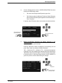
1.
+
Enter
With the APR deactivated, press simultaneously “APR ON/OFF” and
“Enter” buttons. All the LEDs of the Edition Module buttons lights up.
Edition Module with “Edit-Arrow”
buttons and “Enter” button
Display Selector
REGION1
REGION2
REGION3 REGION4
REGION5
REGION6
REGION7 REGION8
ENTER REGION
The Edition Module is operated with the “Edit-Arrow” buttons, the “Enter”
button and the Display Selectors.
Press the “Edit-Arrow” buttons to scroll in the APR Display. When
pressing the Display Selector on the left lower corner, the APR Display
will show sequentially the selected Region / View / Projection at the upper
line.
AP-0015R2
23
HF Series Generators
Appendix -- Quick Installation Guide for TXR Generators
2.
Enter Selection and
go to next screen
Body Region. Once the desired Body Region (highlighted) is chosen
with the “Edit-Arrow” buttons, if the operator requires to modify the
Region name, go to step 3. If not, press the Display Selector close to
“ENTER REGION” to go to step 4.
REGION1
REGION2
REGION3 REGION4
REGION5
REGION6
REGION7 REGION8
ENTER REGION
3.
Modify the Region name. Press “Enter” to edit the name of the selected
Region. The first letter of the name is highlighted, the “Up/Down
Edit-Arrow” buttons will change the letter in alphanumerical order (plus
underscore and blank), the “Right/Left Edit-Arrow” buttons will scroll in
the word. Once the name is written, press “Enter” to save the new Region
name. If necessary, repeat this process to rename other Regions.
R EGION1
Enter Selection and
go to next screen
REGION1
REGION2
REGION3 REGION4
REGION5
REGION6
REGION7 REGION8
Edit name
ENTER REGION
Press the Display Selector close to “ENTER REGION” to go to step 4.
24
AP-0015R2
HF Series Generators
Appendix -- Quick Installation Guide for TXR Generators
4.
Anatomical View. Once the desired Anatomical View (highlighted) is
chosen with the “Edit-Arrow” buttons, if the operator requires to modify
the View name, go to step 5. If not, press the Display Selector close to
“ENTER VIEW” to go to step 6.; or “BACK” to return to the previous
screen.
REGION1
VIEW1
Enter Selection and
go to next screen
VIEW5
VIEW2
VIEW3
VIEW4
VIEW6
VIEW7
VIEW8
ENTER VIEW
5.
Go to previous screen
BACK
Modify the View name. Press “Enter” to edit the name of the selected
View. The first letter of the name is highlighted, the “Up/Down Edit-Arrow”
buttons will change the letter in alphanumerical order (plus underscore
and blank), the “Right/Left Edit-Arrow” buttons will scroll in the word.
Once the name is written, press “Enter” to save the new View name. If
necessary, repeat this process to rename other Views.
VIEW 3
REGION1
VIEW1
VIEW2
VIEW3
VIEW4
Edit name
Enter Selection and
go to next screen
VIEW5
VIEW6
ENTER VIEW
VIEW7
VIEW8
Cancel and go to
previous screen
CANCEL
Press the Display Selector close to “CANCEL” to go back to previous
screen without saving the changes or press the Display Selector close
to “ENTER VIEW” to go to step 6.
AP-0015R2
25
HF Series Generators
Appendix -- Quick Installation Guide for TXR Generators
6.
Projection. Once the desired Projection (highlighted) is chosen with the
“Edit-Arrow” buttons, if the operator requires to modify the Projection, go
to step 7. If not, press the Display Selector close to “ENTER
PROJECTION” to go to step 8. or “BACK” to return to the previous
screen.
REGION1
PROJECT1
Enter Selection and
go to next screen
PROJECT4
VIEW3
PROJECT2
PROJECT3
PROJECT5
Go to previous screen
ENTER PROJECTION
7.
Modify the Projection name. Press “Enter” to edit the name of the
selected Projection. The first letter of the name is highlighted, the
“Up/Down Edit-Arrow” buttons will change the letter in alphanumerical
order (plus underscore and blank), the “Right/Left Edit-Arrow” buttons
will scroll in the word. Once the name is written, press “Enter” to save the
new Projection name. If necessary, repeat this process to rename other
Projections.
REGION1
PROJECT1
Enter Selection and
go to next screen
BACK
VIEW3
PROJECT 1
PROJECT2
PROJECT3
Edit name
PROJECT4
PROJECT5
ENTER PROJECTION
Cancel and go to
previous screen
CANCEL
Press the Display Selector close to “CANCEL” to go back to previous
screen without saving the changes or press the Display Selector close
to “ENTER PROJECTION” to go to step 8.
26
AP-0015R2
HF Series Generators
Appendix -- Quick Installation Guide for TXR Generators
8.
Once the Display Selector close to “ENTER PROJECTION” has been
pressed, the APR Display shows:
G
The name of the Region/View/Projection (upper line).
G
The Thickness values for Minimum Thickness, Default Thickness
and Thickness Step that might be applied to the selected Region /
View / Projection.
If required, these Thickness values can be edited as described below:
REGION1
VIEW3
PROJECT1
MINIMUM THICKNESS:
Enter Selection and
go to next screen
3 cm
DEFAULT THICKNESS:
5 cm
THICKNESS STEP:
2 cm
ENTER TECHNIQUE
9.
Go to previous screen
BACK
Modify the Minimum Thickness, the Default Thickness or the
Thickness Step. If the operator decides to modify a Thickness value,
follow this step, if not, go to next step.
Press the “Edit-Arrow” button to highlight the corresponding line and
press “Enter” button to modify the selected Thickness.
“MT:__” (minimum), “DT:__” (default) or “TS:__” (thickness step) appears
at the right corner of the Display, then select the desired number with the
“Edit-Arrow” buttons and press “Enter” to save the changes and go back
to previous screen, or press the Display Selector close to “CANCEL” to
go back to previous screen without saving the changes.
REGION1
VIEW3
PROJECT1
MINIMUM THICKNESS:
3 cm
DEFAULT THICKNESS:
5 cm
THICKNESS STEP:
2 cm
MT:_ 3
Edit
Thickness
CANCEL
AP-0015R2
Cancel and go to
previous screen
27
HF Series Generators
Appendix -- Quick Installation Guide for TXR Generators
Minimum Thickness (MT__) sets the minimum value in centimeters used
for the selected Region/View/Projection.
Default Thickness (DT__) sets the default value in centimeters according
to the operator preferences.
Thickness Step (TS__) sets the number of centimeters between each
thickness value. Each Region/View/Projection may have a maximum of
twenty (20) Steps.
Note
.
The maximum range for a Thickness value is 99 cm, which means
that a Minimum Thickness value too high or a Thickness Step too
large will not be allowed if the resulting value is over 99 cm.
Calculate if the Thickness values are allowed by applying the formula:
(MT + 19) x TS
where:
MT = Minimum Thickness
19 = Maximum number of Steps minus one
TS = Thickness Step value
For example, in the figure below, the formula is (3+19) x 2 = 44 cm.
In which “3” is the Minimum Thickness, “19” is the number of Steps (20--1)
and “2” is the Thickness Step value. “44” is the resulting maximum
Thickness but if the Thickness Step value is 8, it would not be allowed
as the range is over 99 cm: (3+19) x 8 = 168 cm.
REGION1
VIEW3
MINIMUM THICKNESS:
3 cm
DEFAULT THICKNESS:
5 cm
THICKNESS STEP:
2 cm
ENTER TECHNIQUE
28
PROJECT1
BACK
AP-0015R2
HF Series Generators
Appendix -- Quick Installation Guide for TXR Generators
10.
Modify the Radiographic Technique Values. In order to modify the
Radiographic Technique values for a specific Region/View/Projection,
press the Display Selector close to “ENTER TECHNIQUE”.
REGION1
VIEW3
MINIMUM THICKNESS:
Enter Selection and
go to next screen
PROJECT1
3 cm
DEFAULT THICKNESS:
5 cm
THICKNESS STEP:
2 cm
ENTER TECHNIQUE
Go to previous screen
BACK
The Display will show the Region, View, Projection and the Default
Thickness (highlighted) for the selected Region/View/Projection. Press
“Enter” to edit the APR technique for the displayed Thickness, or
before pressing “Enter” modify the Thickness with the “Up/Down
Edit-Arrows” if the APR technique to be modified corresponds to another
Thickness value.
REGION1
THCK:
VIEW3
Enter
PROJECT1
3 cm
Change
Thickness value
CANCEL
Cancel and go to
previous screen
After pressing “Enter”, the Console automatically displays all the
radiographic parameters (kVp, mA, mAs, Time), selections (Workstation
and AEC) and SID indication related to that Region/View/Projection.
Now, the operator can modify and store the Radiographic Parameters,
Workstation, AEC Selections and SID indication (36”, 40”, 60” or 72”
selected with the “Up/down Edit-Arrows”).
AP-0015R2
29
HF Series Generators
Appendix -- Quick Installation Guide for TXR Generators
Keep in mind that all Thickness values of a Projection will share the same
AEC values, Workstations and SID, that means that if one of these
Parameters is modified, it will affect to all Thickness values for that
specific Region - View - Projection.
AEC, Workstations and SID are common values for all Thickness in a Projection.
EDIT
REGIONX
125
VIEWZ
80.0
THCK
7
250
.320
CANCEL
REGION1 VIEW3
PROJECT1 THCK:3
SID 40”
2
CANCEL
Note
30
.
If an APR technique is to be stored with AEC parameters, a
suitable back-up time (and/or mAs) MUST be stored in the
program by the operator.
11.
Press “Enter” to save in memory the new parameters and selections
assigned to the selected Region/View/Project and Thickness value.
12.
Press simultaneously “APR ON/OFF” and “Enter” buttons to exit from the
APR edition mode.
AP-0015R2
'%!$#"&
#
$%#'%#!
""#"('#%-7< &$%#)'#&($$ ,#"'%# "$#*%*%"#%#'
'(,"'' #%* &'" '% #&/ (,0&%$%1*%''' #%* &'"/
#!! $%!#!"(
"+*,),*,
"%'#%2
%!" '%$193#"#%""'%
#"'4
'#'%$3!%' 4
7
8
9
:
<
", %'%#("""'
%!" '%$2=;3!#("'#"
%'&##"'%# "'4
' ' $%
%
# #%
3$%1*%4
%!" '%$
%# #%
(
%"
'
#*
%#*"
%"
7
8
9
%#("
#%"'%('#%
8:
8:
#'." #"'"('%#((,
("'#"#+/#''%!"''' #$%"'
%('#%/
$%
(%$ (%$ (
%"
'
#*
%#*"
%"
#
"%'#%2
%!" '%$19
'3!%* 4
7
8
9
:
<
", %'%#("""'
%!" '%$2=;3!#("'#"
%'&##"'%# "'4
' ' $%
(%$ Technical Pamphlet W-2009-7-20
%
# #%
(
%"
'
#*
%#*"
%"
3$%1*%4
%!" '%$
%# #%
7
(
8
%"
9
'
#*
%#*"
%#("
%"
'"#%"'%('#%
8:
8:
#'." #"'"('%#((,
("'#"#+/#''%!"''* &'" #
$%"'%('#%/
$%
(%$ 31
2
Pamphlet W-2009-7-20
3Technical
Technical Pamphlet W-2009-7-20
32
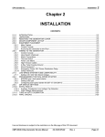
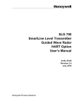
(&!$#"'
#
! $&!#!")!"
#&($&0
&"#!(&%086
1!$($#&('$'*#$)($$&2
86/:
86/;
86/9
86/8
86/6
#,!!&(&$)###(
&"#!(&%0>;1"$)#($#
($%$$#(&$!)#(2
(!
(!
! %&
)&%!
&
$!$&
!)
&#
(
&$*#
!!$*
&#
1%&/*&2
&"#!(&%
&$!$&
6
7
8
&$)#
!
$ &#(&)($&
!)
&#
(
&$*#
!!$*
&#
79
79
! $(-#! $#(#)(&$)) ,
)#($#$+.$((&"#(((!!$ %&#(
&)($&.
%&
)&%!
)%$!"!#!
62)"%86/7($86/8
72)"%86/6($86/7<
#
#&($&0
&"#!(&%086
1!$($#&('$'*#$)($$&2
86/67
86/68
86/66
86/65
86/=
#,!!&(&$)###(
&"#!(&%0>;1"$)#($#
($%$$#(&$!)#(2
(!
(!
! %&
)&%!
&
$!$&
!)
&#
(
&$*#
!!$*
&#
1%&/*&2
&"#!(&%
&$!$&
6
!)
7
&#
8
(
&$*#
!!$*
&$)#
&#
!!(#
$ &#(&)($&
79
79
! $(-#! $#(#)(&$)) ,
)#($#$+.$((&"#((*!!'(#!$ %&#(&)($&.
%&
)&%!
)%$!"!#!
62)"%86/>($86/65
72)"%86/=($86/7<
Technical Pamphlet W-2009-7-20
33
3Technical
4
Pamphlet W-2009-7-20
34
Technical Pamphlet W-2009-7-20