1
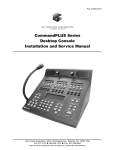
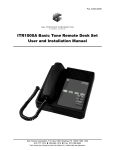
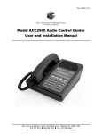
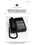
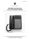
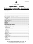
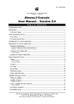
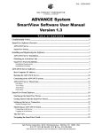
Pub. 43004-026C GAI-TRONICS® CORPORATION A HUBBELL COMPANY Model XAAB002A Audio Accessory Box Installation and Service Manual GAI-Tronics Corporation P.O. Box 1060, Reading, PA 19607-1060 USA 610-777-1374 800-492-1212 Fax: 610-796-5954 VISIT WWW .GAI-TRONICS.COM FOR PRODUCT LITERATURE AND MANUALS CONFIDENTIALITY NOTICE This manual is provided solely as an operational, installation, and maintenance guide and contains sensitive business and technical information that is confidential and proprietary to GAI-Tronics. GAI-Tronics retains all intellectual property and other rights in or to the information contained herein, and such information may only be used in connection with the operation of your GAI-Tronics product or system. This manual may not be disclosed in any form, in whole or in part, directly or indirectly, to any third party. COMPUTER SOFTWARE COPYRIGHTS This product contains copyrighted computer programs stored in semiconductor memory. These programs are copyrighted by GAI-Tronics Corporation and may not be reproduced in any form without express written permission from GAI-Tronics. WARRANTY GAI-Tronics warrants for a period of one (1) year from the date of shipment, that any GAI-Tronics equipment supplied hereunder shall be free of defects in material and workmanship, shall comply with the then-current product specifications and product literature, and if applicable, shall be fit for the purpose specified in the agreed-upon quotation or proposal document. If (a) Seller’s goods prove to be defective in workmanship and/or material under normal and proper usage, or unfit for the purpose specified and agreed upon, and (b) Buyer’s claim is made within the warranty period set forth above, Buyer may return such goods to GAI-Tronics’ nearest depot repair facility, freight prepaid, at which time they will be repaired or replaced, at Seller’s option, without charge to Buyer. Repair or replacement shall be Buyer’s sole and exclusive remedy, and the warranty period on any repaired or replacement equipment shall be one (1) year from the date the original equipment was shipped. In no event shall GAI-Tronics’ warranty obligations with respect to equipment exceed 100% of the total cost of the equipment supplied hereunder. The applicability of any such third-party warranty will be determined solely by GAI-Tronics. Services. Any services GAI-Tronics provides hereunder, whether directly or through subcontractors, shall be performed in accordance with the standard of care with which such services are normally provided in the industry. If the services fail to meet the applicable industry standard, GAI-Tronics will, for a period of one (1) year from the date of completion, re-perform such services at no cost to the Buyer. Re-performance of services shall be Buyer’s sole and exclusive remedy, and in no event shall GAI-Tronics’ warranty obligations with respect to services exceed 100% of the total cost of services provided hereunder. Limitations/Exclusions. The warranty on any equipment supplied hereunder is subject to Customer’s use in compliance with applicable FCC regulations and manufacturer specifications. The warranties herein shall not apply to, and GAI-Tronics shall not be responsible for, any damage to the goods or failure of the services supplied hereunder, to the extent caused by accident, misuse, abuse, neglect, system design, product modification, failure to follow instructions contained in the product manual, repair, or attempted repair by anyone not authorized by GAI-Tronics, improper installation, installation of parts that do not conform to the quality or specifications of the original parts or accessories, damage or loss occurred during shipment, or any unit which is not new when sold or upon which the serial number has been defaced, modified or removed. The warranty does not extend to damage incurred by natural causes including Force Majeure. The warranty does not cover microprocessors if failure is due to static damage or application of improper voltage. THE WARRANTIES AND REMEDIES CONTAINED HEREIN ARE IN LIEU OF AND EXCLUDE ALL OTHER WARRANTIES AND REMEDIES, WHETHER EXPRESS OR IMPLIED BY OPERATION OF LAW OR OTHERWISE, INCLUDING ANY WARRANTIES OF MERCHANTABILITY OR FITNESS FOR A PARTICULAR PURPOSE. Operational and Maintenance Procedures. Buyer acknowledges that any improper use, maintenance, or modification of the equipment provided hereunder, or use of unqualified maintenance or service technicians will severely impair the operational effectiveness of the entire communication system. Buyer hereby agrees to indemnify, defend and hold GAI-Tronics harmless from and against any and all third party claims arising, in any manner, out of: (a) Buyer’s neglect of the equipment; (b) Buyer’s use of technicians not authorized by GAI-Tronics to service the equipment; or (c) Buyer’s improper use or modification of the equipment or failure to follow the operational and maintenance procedures provided with the equipment. Limitation of Liability/Damages. In no event (even should circumstances cause the exclusive warranties and remedies set forth in the Warranty section to fail of their essential purpose) shall either party be liable for any indirect, incidental, special or consequential damages (including, but not limited to, loss of use, loss of anticipated profits, or damages arising from delay) whether such claims are alleged to have arisen out of breach of warranty, breach of contract, strict or absolute liability in tort, or other act, error or omission, or from any other cause whatsoever, or any combination of the foregoing. 11/06 Publication 43004-026C i Table of Contents FOREWORD ....................................................................................................................................................... 1 SCOPE OF MANUAL.............................................................................................................................................. 1 NOMENCLATURE ................................................................................................................................................. 1 ORDERING REPLACEMENT PARTS ......................................................................................................................... 1 SERVICE AND REPAIR .......................................................................................................................................... 1 FEATURES AND BENEFITS OF THE AUDIO ACCESSORY BOX .................................................................................... 2 FCC INTERFERENCE WARNING ............................................................................................................................ 2 SAFE HANDLING OF CMOS INTEGRATED CIRCUIT DEVICES .................................................................................. 3 PERFORMANCE SPECIFICATIONS ........................................................................................................................... 4 DESCRIPTION .................................................................................................................................................... 5 PHYSICAL DESCRIPTION ...................................................................................................................................... 5 FRONT PANEL ..................................................................................................................................................... 5 REAR PANEL ....................................................................................................................................................... 5 CONNECTOR PIN DESCRIPTIONS ........................................................................................................................... 6 J1, 8-pin Output Connector, Motorola Standard, Mirrored Connector........................................................... 6 J2, GAI-Tronics Ixx Handset Output, Mirrored Connector............................................................................. 6 J3, Desk Microphone, 8-pin Modular, Motorola Standard ............................................................................. 7 J4, GAI-Tronics Handset, 4-pin Modular Connector...................................................................................... 7 J5, Boom Microphone Audio, RCA-type, Phono-Jack Connector ................................................................... 7 J6A and J6B, Headset Dual 1/4-inch Telephone Plug, Carbon Standard Connector ...................................... 8 J7, Alternate Headset, 4-pin Modular, Carbon Standard Connector .............................................................. 8 J8, Power Input, 2.0 mm Barrel Jack Connector............................................................................................ 8 J9, 6-pin Modular Alternate Output, Kenwood Standard Connector .............................................................. 9 J10, Telephone Handset I/O, Carbon Standard Connector............................................................................. 9 P1, Footswitch Connector........................................................................................................................... 10 ACCESSORIES .................................................................................................................................................... 10 OPERATION ..................................................................................................................................................... 11 FUNCTIONAL DESCRIPTION ................................................................................................................................ 11 FUNCTIONS ....................................................................................................................................................... 11 Push-to-Talk (PTT - Radio Key-up).............................................................................................................. 11 Monitor ....................................................................................................................................................... 11 Mute ............................................................................................................................................................ 11 Off-Hook Output (J1 – pin 2) ....................................................................................................................... 12 TELEPHONE INTERFACE ..................................................................................................................................... 12 INSTALLATION ............................................................................................................................................... 13 PLANNING THE INSTALLATION ........................................................................................................................... 13 MECHANICAL RECEIPT INSPECTION .................................................................................................................... 14 MOUNTING ....................................................................................................................................................... 14 EQUIPMENT REQUIRED ...................................................................................................................................... 14 Test Equipment ............................................................................................................................................ 14 Documentation ............................................................................................................................................ 14 11/06 Publication 43004-026C ii Table of Contents Model XAAB002A Audio Accessory Box CABLE INSTALLATION SAFETY CONSIDERATIONS ............................................................................................... 14 POWER CONNECTIONS ....................................................................................................................................... 15 PROGRAMMING SETTINGS.................................................................................................................................. 15 TROUBLESHOOTING..................................................................................................................................... 17 TROUBLESHOOTING THE MODEL XAAB002A AUDIO ACCESSORY BOX............................................................... 17 MAIN CIRCUIT BOARD.................................................................................................................................. 19 SCHEMATICS................................................................................................................................................... 21 DEFINITIONS AND ACRONYMS................................................................................................................... 25 11/06 Publication 43004-026C iii Foreword Scope of Manual This manual offers descriptive data and service information for the GAI-Tronics Model XAAB002A Audio Accessory Box. Service diagrams and printed circuit board details are a part of this service manual. Nomenclature The model number, located on the nameplate on the bottom, specifically identifies GAI-Tronics equipment. If additional options are ordered, the option will be identified on the circuit board. Ordering Replacement Parts When ordering replacement parts or requesting equipment information, please include the complete identification number. This applies to all components, kits, and chassis. If the component part number is not known, the order should include the number of the chassis or kit of which it is a part and sufficient description of the desired component to identify it. Order parts from: Customer Service GAI-Tronics Corporation 400 E. Wyomissing Ave. Mohnton, PA 19540 US: 800-492-1212 Outside US: 610-777-1374 Service and Repair Inoperative or malfunctioning equipment should be returned to the factory for repair. Please call 1-800-492-1212 to obtain a Return Authorization number, published repair prices, and shipping instructions. NOTE: A purchase order or credit card number is required prior to processing non-warranty repairs. 1 11/06 Foreword Model XAAB002A Audio Accessory Box Features and Benefits of the Audio Accessory Box Feature Benefit Multiple dispatch microphones are possible Effortless changing of microphones preferred by different shift operators. Radio/telephone interface Allows dispatch over radio and telephone simultaneously with the same headset Small, compact size Fits easily into most set-up configurations and uses little desk top space Efficient, streamlined microphone connections Eliminates messy, jury-rigged microphone hook-ups Top cover can also be used as a mounting bracket Allows multiple mounting configurations for customized set-up Use with remote desktop controller or stand-alone. Provides flexibility by connecting directly to the radio for stationary or mobile applications. FCC Interference Warning The FCC requires that manuals pertaining to Class A and Class B computing devices must contain warnings about possible interference with local residential radio and TV reception. This warning reads as follows: NOTE: This equipment has been tested and found to comply with the limits for a Class A digital device, pursuant to Part 15 of the FCC Rules. These limits are designed to provide reasonable protection against harmful interference when the equipment is operated in a commercial environment. This equipment generates, uses, and can radiate radio frequency energy and, if not installed and used in accordance with the instruction manual, may cause harmful interference to radio communications. Operation of this equipment in a residential area is likely to cause harmful interference in which case the user will be required to correct the interference at his own expense. 11/06 2 Model XAAB002A Audio Accessory Box Foreword Safe Handling of CMOS Integrated Circuit Devices Many of the integrated circuit devices used in communications equipment are of the Complementary Metal Oxide Semiconductor (CMOS) type. Because of their high open circuit impedance, CMOS integrated circuits are vulnerable to damage from static charges. Care must be taken handling, shipping, and servicing them and the assemblies in which they are used. Even though protection devices are provided in CMOS integrated circuit inputs, the protection is effective only against overvoltage in the hundreds of volts range such as is encountered in an operating system. In a system, circuit elements distribute static charges and load the CMOS circuits, decreasing the chance of damage. However, CMOS circuits can be damaged by improper handling of the modules, even in a system. To avoid damage to circuits, observe the following handling, shipping, and servicing precautions: 1. Prior to and while servicing a circuit module, particularly after moving within the service area, momentarily touch both hands to a bare metal, earth-grounded surface. This will discharge any static charge that may have accumulated on the person doing the servicing. NOTE: Wearing a conductive wrist strap will minimize static build-up during servicing. 2. Whenever possible, avoid touching any electrically conductive parts of the circuit module with your hands. 3. Power down the unit before installing or removing the circuit module. 4. When servicing a circuit module, avoid carpeted areas, dry environments, and certain types of clothing (silk, nylon, etc.) because they contribute to static build-up. Similarly, disconnect the test probe prior to removing the ground lead. 5. All electrically powered test equipment should be grounded. Apply the ground lead from the test equipment to the circuit module before connecting the test probe. 6. If a circuit module is removed from the system, it is desirable to lay it on a conductive surface (such as a sheet of aluminum foil) which is connected to ground through 100k of resistance. 7. When soldering, be sure the soldering iron is grounded, and has a grounded tip. 8. Prior to connecting jumpers, replacing circuit components, or touching CMOS pins (if this becomes necessary in the replacement of an integrated circuit device), be sure to discharge any static build-up as described in procedure 1. Since voltage differences can exist across the human body, it is recommended that only one hand be used if it is necessary to touch pins on the CMOS device and associated board wiring. 9. When replacing a CMOS integrated circuit device, leave the device in its conductive rail container or conductive foam until it is to be inserted into the printed circuit module. 10. All low impedance test equipment (such as pulse generators, etc.) should be connected to CMOS device inputs after power is applied to the CMOS circuitry. Similarly, such low impedance equipment should be disconnected before power is turned off. 11. Replacement modules shipped separately from the factory will be packaged in a conductive material. Any modules being transported from one area to another should be wrapped in a similar material (aluminum foil may be used). Never use non-conductive material for packaging these modules. 3 11/06 Foreword Model XAAB002A Audio Accessory Box Performance Specifications Color ................................................................................................................................................ Black Physical size.......................................................................................... 1.55 H × 6.40 W × 4.25 D inches Shipping weight ................................................................................................................................ 3 lbs. Power input ...................................................................................... 9.0 to 16.0 V dc, 100 mA, maximum Receive audio input..................................................................................................... 100 mV ac nominal Transmit audio output............................................................................. 80 mV ac nominal into 600 ohms Environment: Ambient temperature, operation ............................................................................................ 0º C to 60º C Ambient temperature, storage........................................................................................... -40º C to 100º C Ambient humidity, non-condensing...................................................................................................... 90% Microphone inputs with respect to 80 mV ac output: Desk mic, selectable............................................................................................. 25 mV ac or 800 mV ac Ixx Handset, nominal ................................................................................................................. 25 mV ac Boom mic, selectable ....................................................................... 200 µV ac or 850 µV ac or 15 mV ac Headset mic, selectable ........................................................................................ 25 mV ac or 800 mV ac Nominal microphone gain selections: Desk mic ...................................................................................................................... +10 dB or –20 dB Ixx Handset ...................................................................................................................... +10 dB or unity Boom mic ..................................................................................................... +51 dB or +40 dB or +15 dB Headset mic.................................................................................................................. +10 dB or –20 dB Noise floor (S+N/N) .......................... Greater the -45 dB below rated output except high gain on boom mic Logic output levels............................................................................................ 5-volt, CMOS-compatible Audio distortion............................................................................................................Less than 2% THD 11/06 4 Description Physical Description The GAI-Tronics Model XAAB002A Audio Accessory Box measures 1.55 H × 6.40 W × 4.25 D inches. It contains five connectors and an optional mute radio push button on the front panel, and the rear panel contains six connectors. A seventh connector, J10, is an available option. It is shipped with a 9-volt dc wall plug-in power supply, a 7-foot RJ45 male-male 8-pin modular cable (mirror-connected), a 6-foot 4-pin retractile cord, and a dc power connector. The XAAB002A also includes a cover that can be used as a bracket in specific mounting arrangements described in the Installation section. Optional accessories, such as microphones, headsets, footswitches, etc. must be ordered separately. Front Panel Refer to the figure below for the locations of the connectors and optional mute push button on the front panel of the accessory box. Model XAAB002A Audio Accessory Box - Front Panel Rear Panel The rear panel of the accessory box is shown below. Note that connector J10 is optional. Model XAAB002A Audio Accessory Box - Rear Panel 5 11/06 Operation Model XAAB002A Audio Accessory Box Connector Pin Descriptions J1, 8-pin Output Connector, Motorola Standard, Mirrored Connector J1 is the main output connector to the radio, a console, or an Advanced desk set (towards radio). The pin-out is mirrored with respect to a Motorola standard 8-pin modular mic jack. See the pin-out below. NOTE: Mirrored pin-out (opposite of pin-to-pin) is used on output connectors so a standard off-the-shelf male-male modular cable will connect properly. Table 1. J1, 8-Pin Output Connector Pin-out Pin No. Function 1 RX audio from radio to handset and headset. Nominal level = 100 mV ac 2 Handset off-hook logic low output towards radio (or console) 3 PTT logic low output towards radio 4 TX audio output towards radio Nominal level = 80 mV ac 5 Audio ground 6 Monitor logic output towards radio 7 Not connected 8 DC power input (from some radios or consoles) J2, GAI-Tronics Ixx Handset Output, Mirrored Connector J2 is the GAI-Tronics handset “through-function” output connector. The accessory box can be placed electrically between the handset and its respective desk set. This enables the audio accessory box to control handset functions. J2 is mirrored for easy connection to the desk set handset jack. The pin-out for J2 is shown below. NOTE: Mirrored pin-out (opposite of pin-to-pin) is used on output connectors so a standard off-the-shelf male-male modular cable will connect properly. Table 2. J2, GAI-Tronics Handset Output Pin-out Pin No. 11/06 Function 1 Audio ground 2 Handset analog logic functions 3 RX audio from radio. Nominal level = 100 mV ac 4 TX audio towards radio. Nominal level = 25 mV ac 6 Model XAAB002A Audio Accessory Box Operation J3, Desk Microphone, 8-pin Modular, Motorola Standard J3 is the connector for the desktop microphone, Model XDM002A. The pin-out matches the Motorola standard 8-pin modular desk mic. Table 3. J3 Desk Mic Connector Pin-out Pin No. Function 1 Not connected 2 Not connected 3 Monitor logic input from desk mic 4 Audio ground 5 TX audio towards radio. Nominal level = 80 mV ac 6 PTT logic low output towards radio 7 Not connected 8 RX audio from radio. Nominal level = 100 mV ac J4, GAI-Tronics Handset, 4-pin Modular Connector J4 is the connector for the GAI-Tronics handset. Table 4. J4 GAI-Tronics Handset Connector Pin-out Pin No. Function 1 TX audio towards radio. Nominal level = 25 mV ac 2 RX audio from radio. Nominal level = 100 mV ac 3 Handset analog logic functions 4 Audio ground J5, Boom Microphone Audio, RCA-type, Phono-Jack Connector J5 is an RCA-type audio jack that is used as the connector for a boom, a Model XGM002A Gooseneck Microphone, or a Model XDM003A Desktop Mic. Table 5. J5 Boom Microphone Audio, Phono-Jack Connector Pin Function Descriptions Pin Description Function Center pin TX audio input Outer shield Audio ground 7 11/06 Operation Model XAAB002A Audio Accessory Box J6A and J6B, Headset Dual 1/4-inch Telephone Plug, Carbon Standard Connector J6A and J6B are headset connections for ‘carbon standard’ (twin 1/4-inch) phone plugs. These connectors will accommodate low impedance, electret, or amplified-dynamic type headsets such as Model XHS0003A with XCC003A Coiled Cord. PTT on the ring terminals is also supported. Table 6. J6A and J6B Headset Dual Telephone Plug Connector Pin Function Descriptions Pin Description Function Tips TX audio towards radio Sleeves RX audio from radio Rings PTT logic sense J7, Alternate Headset, 4-pin Modular, Carbon Standard Connector J7 is parallel to J6/J7. This is the 4-pin modular headset connection for the GAI-Tronics Model XHS002A Headset. The pin descriptions are shown in the table below. Table 7. J7 Alternate Headset Connector Pin Function Descriptions Pin Description Function 1 Red wire TX audio 2 White wire RX audio 3 Green wire RX audio 4 Black wire TX audio J8, Power Input, 2.0 mm Barrel Jack Connector J8 is a barrel-type power connector for external 9 to 16 V dc. The center post is positive. This is the preferred power input for optimum performance. Table 8. J8 Power Input Pin-out Pin Description Function Center pin 9–16 V dc input, positive Outer barrel Ground, negative 11/06 8 Model XAAB002A Audio Accessory Box Operation J9, 6-pin Modular Alternate Output, Kenwood Standard Connector The J9 is the alternate main output connector in a mirrored 6-pin mirrored jack that is connected to plug-and-play with Kenwood radios. Table 9. J9 Modular Alternate Output Pin-out Pin No. Function 1 Monitor logic output towards radio 2 TX audio output towards radio. Nominal level = 80 mV ac 3 Audio ground 4 PTT logic low output towards radio. 5 Logic ground 6 Not connected J10, Telephone Handset I/O, Carbon Standard Connector NOTE: Pin-out matches telephone handset end. The J10 is the handset output connector where a carbon standard telephone handset cord is plugged in for the telephone dispatch option. The headset hears the audio from the telephone party as well as the radio. The telephone off-hook and dialing must be done manually by the radio user. Table 10. J10 Telephone Handset I/O Pin-out Pin Description Function 1 Black wire TX audio – 2 Green wire RX audio 3 White wire RX audio 4 Red wire TX audio + 9 11/06 Operation Model XAAB002A Audio Accessory Box P1, Footswitch Connector P1 is the connection for the GAI-Tronics Model XFS002A Footswitch. It supports the monitor and PTT functions. Table 11. P1 Footswitch Connector Pin-out Pin No. Function 1 Footswitch PTT (transmitter key-up) logic low input 2 Logic ground 3 Footswitch monitor logic low input Accessories Description Part No. Desktop Microphone XDM002A Desktop Microphone, Heavy-duty XDM003A Headset XHS002A Headset (requires XCC003A Coiled Cord) XHS003A Coiled Cord (with PTT switch) XCC003A Gooseneck Microphone, Lightweight XGM002A Gooseneck Microphone, Heavy-duty XGM003A Footswitch XFS002A DC Power Supply (replacement) XPS002A 11/06 10 Operation Functional Description The GAI-Tronics Model XAAB002A Audio Accessory Box is an appliance for consolidating various audio input/output devices associated with two-way dispatch radio service. Audio paths through the device are enabled as needed depending on the device being used at any given time, and are configured for the optimal signal levels associated with currently available microphones, headsets and handsets. Several operating parameters vary the signal levels and logical behavior of the various devices. They are selectable with programming switches. After initial installation of the Audio Accessory Box, no user interface is required. For information on the operation of the various accessories, refer to the associated user manuals. Functions Push-to-Talk (PTT - Radio Key-up) Push-to-talk can be initiated from the paddle on the desk mic, the TRANSMIT bar on the desk set, handset PTT bar, the footswitch, or a PTT button associated with a headset. PTT is sensed individually at each mic connector, and this action routes the transmit audio through the path associated with that type of mic. See Table 12. Jumper Settings on page 15 in the Description section. Monitor Monitor is operated from the same sources as above. This function is used primarily in analog radio where two or more radio systems share a common channel frequency. The monitor pedal on the footswitch can also be used to momentarily mute audio coming from the telephone party. See Programming Settings in the Installation section. Mute The optional mute switch on the front panel momentarily mutes radio receive audio to the headset. 11 11/06 Operation Model XAAB002A Audio Accessory Box Off-Hook Output (J1 – pin 2) The off-hook output located on J1 (8-pin output connector) is asserted when either the handset connected to the J4 (GAI-Tronics handset connector) is taken off-hook, or when a headset is connected to J6A and J6B (headset dual ¼-inch telephone plug). This signal is used by the audio accessory box to select the correct microphone and may be used to route audio appropriately in the connected unit. When a GAI-Tronics handset is not connected to J4 or is not able to be placed on-hook, it appears that the handset is off-hook to the audio accessory box. Therefore, when not using a GAI-Tronics handset, the internal jumper, JU1, must be in. Always allow a short delay before speaking to allow time for the radio channel to be established. The TRANSMIT button or handset PTT bar must be held down while talking to the radio user and released to listen. When the transmission is completed, the TRANSMIT LED extinguishes and the desk set returns to the receive mode. Telephone Interface This feature allows the operator to use a common headset/microphone for both radio and telephone operation. No telephone-to-radio patching will occur. The radio communication can be muted during a telephone communication by pressing the MUTE RADIO push button on the unit’s front panel. NOTE: The telephone must be in off-hook mode for the headset to be active. 11/06 12 Installation Planning the Installation Sample installation diagrams for the XAAB002A when used with desktop controllers Sample installation diagram for the XAAB002A when used directly with radio 13 11/06 Installation Model XAAB002A Audio Accessory Box Mechanical Receipt Inspection The XAAB002A Audio Accessory Box is shipped in a cardboard container with inserts. Thoroughly inspect it as soon as possible after delivery. In-transit damage should be immediately reported to the transportation company. Mounting The Audio Accessory Box can sit on a desktop or can be mounted to the side or under the desk by means of mounting screws through the top cover piece. In this case, the chassis bottom piece is rotated 180° and secured upside down into the cover after the cover has been mounted under the desk or tabletop. Equipment Required Test Equipment • • • RF service monitor #1 Phillips screwdriver 1/8-inch flat blade screwdriver Documentation • • instruction manuals from optional accessories these installation instructions Cable Installation Safety Considerations Interconnecting, communications, and Class 2 dc power cables should be separated from electrical light or other Class I circuits by at least 2 inches. The exception is where Class I wiring or power circuits are run in a raceway, or are metal-sheathed or metal-clad, or are permanently separated from the conductors of the other circuitry by a continuous and firmly fixed nonconductor such as porcelain tubes or flexible tubing in addition to the insulation on the wire. Communications cables and in-building wiring should be listed and marked for the purpose according to NEC Article 800. 11/06 14 Model XAAB002A Audio Accessory Box Installation Power Connections Plug in the supplied wall transformer and connect the power into J8 on the XAAB002A. For direct mobile radio use, connect 12 V dc from the radio to the audio accessory box via the dc connector provided (which plugs into J8). Programming Settings The various microphone gains and logic polarities are set up with programming switches located on the PCBA. The cover must be removed to gain access to these switches. Refer to the following tables. The internal programming switch parameters are as follows: Table 12. Jumper Settings Jumper Position Function JU1 IN (shorted) OUT (Not shorted) Handset not connected to J4 - does not generate off-hook Handset is connected to J4. JU2 IN (shorted) OUT (Not shorted) Handset mic is always on. Handset mic is PTT-controlled. JU3 IN (shorted) OUT (Not shorted) Desk mic is always on. Desk mic is PTT-controlled. JU4 IN (shorted) OUT (Not shorted) Boom mic is always on. Boom mic is PTT-controlled. JU5 IN (shorted) OUT (Not shorted) Headset mic is always on. Headset mic is PTT-controlled. JU6 IN (shorted) OUT (Not shorted) Headset RX level is normal. Headset RX level - Add 10 dB. 15 11/06 Installation Model XAAB002A Audio Accessory Box Table 13. SWA Switch Settings Switch Position Function SWA-1 On Off Not used SWA-2 On Off Mic loop-back test Normal SWA-3 On Off BOOM MIC - add 25 dB gain SWA-3 and SWA-4 = fixed gain SWA-4 On Off BOOM MIC - add 36 dB gain SWA-3 and SWA-4 = fixed gain SWA-5 On Off HEADSET MIC - add 10 dB gain 20 dB loss SWA-6 On Off DESK MIC 10 dB gain 20 dB loss SWA-7 On Off Ixx HANDSET MIC 10 dB gain Unity gain SWA-8 On Off Bias voltage to BOOM MIC No bias voltage Table 14. SWB Switch Settings Switch Position Function SWB-1 On Off Enable DC POWER input from DESK MIC AUX POWER only SWB-2 On Off HEADSET sense generates Ixx OFF-HOOK No effect on off hook SWB-3 On Off Lock HEADSET SENSE gating function ON Normal SWB-4 On Off FOOTSW TRANSMIT enables DESK MIC DESK MIC enabled only with desk mic PTT SWB-5 On Off FOOTSW TRANSMIT enables BOOM MIC BOOM MIC disable SWB-6 On Off FOOTSW MONITOR mutes TELEPHONE RX audio No mute SWB-7 On Off DESK MIC OUT MONITOR logic LOW Output logic HI SWB-8 On Off DESK MIC INPUT MONITOR logic LOW Input logic HI 11/06 16 Troubleshooting Troubleshooting the Model XAAB002A Audio Accessory Box The following is a list of potential problems you may encounter and possible solutions. Problem Possible Solution Microphone PTT switch will not key up the transmitter. Check the logic polarity required by the radio. This unit outputs a 5-volt logic low. No TX audio from headset. Headset may be high impedance (electret or ceramic mic) and not able to trip headset sense circuitry. Try SWB-3 switched to ON. Headset inoperable Headset may not conform to ‘carbon standard’ connector pin-out. Check connector pin functions. Headset may require an amplifier or adapter cable supplied by the headset manufacturer. Telephone interface option is not working. Telephone set must conform to carbon standard, sometimes referred to as POTS. 17 11/06 Troubleshooting Model XAAB002A Audio Accessory Box NOTES: 11/06 18 Main Circuit Board 19 11/06 Main Circuit Board Model XAAB002A Audio Accessory Box 20 Schematics 21 11/06 Schematics Model XAAB002A Audio Accessory Box Schematic Diagram - Sheet 1 22 Model XAAB002A Audio Accessory Box Schematics Schematic Diagram - Sheet 2 23 Schematics Model XAAB002A Audio Accessory Box NOTES: 24 Definitions and Acronyms Term Definition Boom Mic A dispatch center microphone suspended from a movable boom so as to position it in mid-air at face level to the operator. Usually contains a dynamic-type microphone element. Carbon Standard PSTN network standard for telephone instruments that features a 50 ohm handset receiver element. Off-hook state must exhibit between 8 and 20 mA dc and have a ringer impedance of 11 kilohms or higher. Hybrid isolation must be 10 dB or better over the voice band. CSQ Carrier squelch Dynamic Microphone A low impedance, low level microphone element requiring high gain interface amplifiers. Electret A medium impedance, wide frequency range microphone element requiring a bias voltage supply. Ixx GAI-Tronics desk set products such as ILD, ITR, IDR, etc. Monitor Action taken to disable the CTCSS or CDCSS system in order to determine if the radio channel is being currently used by other channel licensees. POTS Plain Old Telephone Set: Refers to carbon standard telephone sets having carbon button microphone elements (low impedance) and dynamic earpiece elements. PSTN Public Switched Telephone Network PTT Push-To-Talk (transmitter key-up) RF Radio Frequency: High frequency energy emitted by an electronic device. RX Receive or receiver TX Transmit or transmitter 25 11/06 Notes: Model XAAB002A Audio Accessory Box 26