1
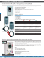
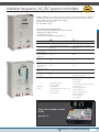
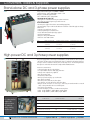
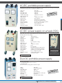
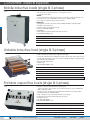
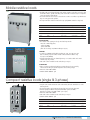
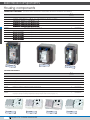
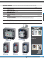
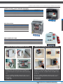
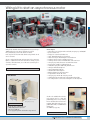
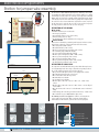
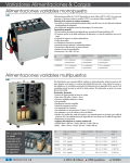
Converters, loads & supplies
AC/AC frequency converters (speed variators)
The variators for 1500W and 3000W machines are frequency converters (at constant V/f) for three-phase
asynchronous squirrel-cage induction motors. Converters are supplied ready-to-use for most applications. They
include a built-in adjusting terminal (4-digit display, 7 segments, and 4 knobs) to customize your application
by modifying the settings as required and extend the functions. A potentiometer on the front is used to adjust the
converter's sampling frequency, and thus the motor rotation speed. Dimensions: 360 x 270 x 170 mm.
Link jump to choose the rotation’s direction, except VAR-BOX.
MAIN COMMON FUNCTIONS
Main configurable functions
• Up to 8 preselected speeds
• Rapid stop, freewheel stop, etc.
• Acceleration/deceleration slope
• Default reset
• Sense of rotation choice
Converter protection and safety systems
• Short-circuit protection:
on outputs, between phases
• Internal power supply
• On outputs, between phases and earth
• Overheating and overcurrent protection
Motor protection
• Heat protection built into the converter by calculating I2t
• Phase outage protection
Ref
ACVAR5
ACVAR7
ACVAR6
VAR-BOX
Motor power
up to 1500W
up to 1500W
up to 3000W
up to 1500W
Power supply
200 to 240V single
200 à 240V single
380 à 400V 3-phase 200 à 240V single
Frequency
50/60Hz
50/60Hz
50/60Hz
50/60Hz
Output voltage
220V 3-phase
220V 3-phase
380V 3-phase
220V 3-phase
8A
7.1A
8A
12A
12A
10,7A
12A
150%
torque rating
150%
torque rating
150%
torque rating
150%
torque rating
no
yes
no
no
Constant output current 8A
Maximum transient
current
Transient overtorque
(60s)
Emergency
stop push button
TECHNICAL SPECIFICATIONS OF VAR-BOX
All inputs and outputs of the frequency converter are present on safety sockets 4mm on the front panel:
Power terminals
• Mains inputs/outputs to the motor
• Output to a brake resistance (PA/+, PB, PC/-)
Control terminals
• Control inputs: 0-10V, 4-20mA, potentiometer (AI3, COM, AOV, AOC, AI1, 10VAI2)
• Relay contacts outputs (R1A, R1B, R1C, R2A, R2C)
• Logic inputs (24C, LI1, LI2, LI3, LI4, LI5, LI6, CLI)
1 potentiometer 5 kΩ, output on 3 sockets
1 On/Off switch, output on 2 sockets
OPTION SOFTWARE
Your computer - using the LOGY-SCH1 option - can controlled these
frequency converters by RS232 connection. A complete control panel
displayed on your screen is used to monitor and control motor
operations.
Full software supplied with converter-computer link cables.
ref. LOGY-SCH1
92
PRODUCTS 2 YEARS GUARANTEE
3-phase 400V+N
230VAC single-phase
50/60Hz
50Hz
Variable frequency AC/AC speed controllers
These speed controllers for 1500W and 3000W asynchronous machines are for supplying and programming
applications such as belt conveyers, blenders, extruders, pumps, fans and compressors. Putting them into service
is rapid and their
programming console makes them very easy to use. Software specific to each make lets you configure and monitor
operation of the speed controllers. All speed controller and PLC inputs and outputs are available on the front on
Ø4mm safety sockets. A potentiometer lets you adjust the sampling frequency of the speed controller, and the
rotation speed of the motor.
Dimensions 390 x 280 x 185mm.
Supplied with operating/programming instructions, software and USB lead.
MAIN FUNCTIONS COMMON TO THE 4 MODELS
Main configurable functions
• Adjustment of the deceleration/acceleration ramp
• Adjustment of the minimum/maximum speed of rotation
• Quick stop/free wheel
• Input configuration to manage the 2 rotation directions, RUN, stop type, preselected speeds, etc.
• USB lead output for PC link
• Software for speed controller setting
Speed controller and motor protection devices
• Output protection against short-circuits between phases
• Protection against overloads
• Protection against heating
• Protection against phase outages
TECHNICAL CHARACTERISTICS SPECIFIC TO ACVAR325 AND 326
All the speed controller's inputs and outputs are available on safety terminals on the box front:
Power terminals
• Mains input / Output to motor
• Output to braking resistance (PA/+, PB, PC/-)
Ref
ACVAR325
ACVAR326
ACVAR425
ACVAR426
Brand / Type
Schneider / ATV32
Schneider / ATV32
Siemens / G120
Siemens / G120
Motor power
up to 1500W
up to 3000W
up to 1500W
up to 3000W
Power supply
200 to 240V single-phase
380 to 500V 3-phase
380 to 480V 3-phase
380 to 480V 3-phase
Frequency
50/60Hz
50/60Hz
50/60Hz
50/60Hz
Output voltage
3 x 230V
3 x 400V
3 x 400V
3 x 400V
Nominal output current 8A
7.1A
4.1A
7.3A
Software
SoMove
SoMove
Starter
Starter
Bluetooth
Yes
Yes
No
No
Braking resistance
output
Yes
on terminals
Yes
on terminals
Yes
on terminals
Yes
on terminals
Yes
Yes
Yes
6 input binary
1 input Analogue - 10-10VDC
1 input Analogue x…y mA
1 safety input STO
3 binary outputs
1 O. Analogue 0-10V or 0-20mA
1 O. Logic 30V/100mA
6 input binary
1 input Analogue - 10-10VDC
or x…y mA
2 binary outputs
1 O. Analogue 0-10V or 0-20mA
1 O. Logic 30V/500mA
6 input binary
1 input Analogue -10-10VDC
or x…y mA
2 binary outputs
1 O. Analogue 0-10V or 0-20mA
1 O. Logic 30V/500mA
programmation console Yes
Inputs / Outputs
Signals on terminals
6 Input binary
1 Input Analogue - 10-10VDC
1 Input Analogue x…y mA
1 safety input STO
3 binary outputs
1 O Analogue 0-10V or 0-20mA
1 O Logic 30V/100mA
PRODUCTS 2 YEARS GUARANTEE
93
Converters, loads & supplies
Economical AC/AC frequency converters
Variators for three-phase, squirrel-cage asynchronous machines with a power of 300 to 3000W.
With their integrated control console, these variators are easy to use.
Speed control by potentiometer Start/Stop button.
From the control unit, the user can configure:
• the motor's rated characteristics, such as rotation speed, current, voltage, and so on
• the rotational direction
• the acceleration ramp
• the deceleration ramp
• resetting of defaults
OPTIONS * : CONTACT US
• 1 brake resistance output
• 1 fault contact output
• 2 programmable inputs
• 1 analog 0-10V input
• 1 analog 4-20mA input
* These options require to fit these ECOVAR-15 & ECOVAR-30 variators in a plastic box
Reférence
ECOVAR-03
ECOVAR-15
ECOVAR-30
Motor power
Up to 400W
Up to 2200W
Up to 4000W
Supply / Frequency
220V 50/60Hz
on safety
terminals 4mm
220V 50Hz/Single
on 2P+E socket with
power cable 2m
400V 3-phase
on CEI 3-phase socket
with power cable 2m
Output voltage
220V 3-phase
on safety
terminals 4mm
220V 3-phase
on safety
terminals 4mm
400V 3-phase
on safety
terminals 4mm
Constant output current
3A
10A
8,5A
Output frequency
0 – 400Hz
0 – 400Hz
0 – 400Hz
Protection against the short-circuits
Secondary by fuses
between phase
Secondary by fuses
Secondary by fuses
Protection against over-current
yes
yes
possibility to set a maximum frequency
Ref. ECOVAR-15
yes
Instructions manual is supplied with the variator.
Ref. ECOVAR-30
Vector speed controller for encoder motor
Digital speed controller unit with vector flux control for asynchronous and synchronous motor with max power
2000 W (compatible with our 300 W and 1500 W motors). 8-pin connector for linking a 1024-pt encoder. A cut-out,
on the unit front, gives access to the different programming keys and to a screen showing the various settings of the
speed controller. A potentiometer adjusts the speed of
rotation, while a switch controls motor rotation on/off. A set of security terminals gives access to the cabling of 3
programmable inputs (e.g. motor stopping in 'free wheel', reversal of the direction of rotation, preselected speed),
of 2 analogue inputs 0-10 V/4-20 mA and one external braking resistor not supplied.
ref. VCV52
94
Features
• vector speed controller 2.2 kW / 3 HP max.
• Power supply 3x400 V AC 50/60 Hz + Earth
• Output 3x400 V + Earth – 5.5 A
• Speed controller output frequency adjustable from 0.1 to 599 Hz.
• Acceleration and deceleration ramp with separate adjustment.
• Vector control of current flux
• Encoder input 1024 pts
• Protection against phase loss, overcurrent, overvoltage, thermal, etc.
• Dim. 210x245x350mm
PRODUCTS 2 YEARS GUARANTEE
3-phase 400V+N
230VAC single-phase
50/60Hz
50Hz
Variable frequency AC/DC speed controllers
DCVAR2 and DCVAR43 speed controllers control separately excited or permanent magnet DC motors. On the front,
the RUN button powers up the speed controller and the potentiometer varies the speed of rotation of the motor.
The mains and the motor connect to Ø4mm safety terminals.
Supplied with operating instructions.
Dim: 390 x 280mm x 185mm.
Speed controller protection and safety devices
• Mains side input protection by 30mA residual current circuit-breaker
• Output protection against short-circuits
• Protection against overloads
• Thermal protection against abnormal temperature rise
Ref
DCVAR2
DCVAR43
Motor power
from 1500W to 3000W
from 1500W to 3000W
Power supply
110-115V, 220-240V or 380-415V
single-phase
110-115V, 220-240V or 380-415V
single-phase
Frequency
50/60Hz
50/60Hz
Armature output
voltage with power
supply 240V
180V
180V
Nominal armature
current
16A
16A
Field system output
voltage with power
supply 240V
210V
210V
Field system nominal
current
3A max
3A Max
Number of quadrant
in operation
1Q
4Q
(energy release on mains)
- Speed: Max. and Min.
- Current limitation
- Speed stability
- Acceleration/deceleration time 1 to 15s
- Ri compensation
- Zero speed offset
- Speed: Max.
- Current limitation
- Speed stability
- Acceleration/deceleration time 0 to 40s
- Ri compensation
- Speed: Proportional gain
- Speed: Integral gain
- Current: Proportional gain
- Current: Integral gain
- Zero speed offset
- Zero speed limit
Adjustments
on front
Study case for speed controller
ATV32
SEE PAGE 182
PRODUCTS 2 YEARS GUARANTEE
95
Converters, loads & supplies
Stand-alone DC and 3-phase power supplies
Transportable variable supplies unit (2000W or 4000W)
Supply from mains: 3-phase 380V/400V + neutral + earth
Outputs: 2 variable DC supplies 0-250V
and 1 variable AC 3-phase supply 0-430V
PROTECTION OF THE USER IN DC
• DC supplies are isolated from mains by an insulation transformer.
• The outputs are protected against surges and short-circuits.
OTHER SPECIFICATIONS
• The DC power supply is delivered from a Graetz bridge (Ripple 4%)
• The DC auxiliary outputs is with a double alternation rectification of which the ripple rate changes
with the load
• Emergency stop push button - key reset
• Voltage regulation by two autotransformers
• Power cable with industrial 3-phase plug supplied
• Hard-wearing LED lamps
• Outputs on safety terminals Ø 4mm.
• Dimensions 710 x 600 x 375mm
Ref.
OUTPUT 0-250V DC
OUTPUT 0-430V 3-PHASE
AUXILIARY OUTPUT 0-250V
COMPAK20
8A + voltmeter
5A + voltmeter
2,5A + voltmeter
& ammeter
& ammeter
& ammeter
16A + voltmeter
& ammeter
6A + voltmeter
& ammeter
2,5A + voltmeter
& ammeter
COMPAK40
High power DC and 3-phase power supplies
This power supply, which is varied using an autotransformer, can be networked so that it can power
other stations. The DC outputs are insulated from the mains, as stipulated in the standard, and monitored by a continuous insulation monitoring device for the safety of users. This monitoring allows the
DC output to be networked. The transformer complies with the NFEN6158 norm.
INTRODUCTION AND DESCRIPTION:
• Sheet metal cabinet, fitted on a wheeled base.
• For 3-phase 400V + Neutral + Earth supply from mains
• Voltages can be adjusted using a flywheel.
• One disconnecting switch.
• Hardwearing indicator lights
• One key-operated emergency-stop circuit breaker.
• One ammeter for the DC
• One three-position switch: DC / 0 / three-phase
• Two voltmeters: one for the DC and one for the three-phase
• Outputs: Can be connected in one of two ways – either using an internal terminal for a network
cable, or safety terminals for direct use with safety leads.
• Protection: by circuit breakers
• insulation checking by a continuous insulation monitoring device
• UNIT Height: 1000mm / Width: 600mm / Depth: 350mm
• BASE Height: 100mm / Width: 810mm / Depth: 600mm
For safety the DC
outputs are
separated from
the mains by
safety isolating
transformer
96
PRODUCTS 2 YEARS GUARANTEE
Ref.
MAX ELECTRIC CURRENT MAX ELECTRIC CURRENT FOR MAINS SUPPLY
IN DC 0-250V
3-PHASE AC 0-450V
TOTAL
POWER
PSY40K
16A monitored
8A
3-PHASE 400V+N+E
4.000VA
PSY60K
24A monitored
13A
3-PHASE 400V+N+E
6.000VA
PSY90K
36A monitored
13A
3-PHASE 400V+N+E
9.000VA
PSY120K 48A monitored
20A
3-PHASE 400V+N+E
12.000VA
PSY150K 60A monitored
20A
3-PHASE 400V+N+E
15.000VA
3-phase 400V+N
230VAC single-phase
50/60Hz
AC/DC portable power supply
Adjustable from 0 to 230V in DC or AC, this power supply delivers a constant current of 3A. Protected by a thermal-magnetic
circuit breaker, the safety of users is ensured by the separation of circuits.
• Mains input
• On/Off
• DC variable output
• AC variable output
• Variable voltage setting
• Max current DC or AC
• Output displays
• Input protection
• Output protection
• User’s safety
• DC output smoothing
• AC/DC commutation
• Connecting
• Dimensions / Weight
Mains cable
General luminous switch
0-240 volts
TIBLE
COMPA
0-230 volts
OTORS
00W M
WITH 3
rotating knob onto the unit
3A
1 voltmeter and 1 ammeter
by time delay fuse
thermal-magnetic circuit-breaker
all outputs are insulated from mains
by capacitors, without electronic regulation
CC – 0 – CA by rotary switch
Safety terminals 4mm
210 x 245 x 350mm / 25kg
ref. ISOSEC1
AC/DC power supply on wheels (10A)
Supply of AC or DC current in 10A max.AC/DC selector switch on the front of the
unit. Mains cable of 3 metres with plug
• Mains supply
• ON/OFF
• Emergency stop
• DC output
• AC output
• Adjustement
• Max output current
• Outputs display
• Input protection
• Outputs protection
• Users protection
• Filtering ACDC10
• Filtering DC10
• Switching
• Dimensions / Weight
• Wheels
230V, single-phase
push button + LED lamp
with key
0-230V
0-230V
by a rotary button on the top
10A
1 voltmeter et 1 ammeter
by fuse
by circuit breaker
by insulation from mains (in DC mode only
no filtering. double alternation rectification
with filtering. 5% of residual ripple at 10A.
DC – 0 – AC (by rotary switch)
H 510 x P 280 x P 330 mm / 40 kg
2 of them have a brake
ref. DC10
Version without AC output.
For solar system.
Special connections. (P. 132)
ref. ACDC10
Dual DC portable power supply
This power supply includes :
- one variable DC supply with voltmeter & ammeter
- one fixed DC supply
Protection of users is ensured by galvanic insulation of outputs.
• Mains :
• On/Off :
• DC variable output :
• DC fixed output :
• Input protection:
• Output protection :
• Smoothing :
• Dimensions / weight :
Mains cable
General switch and light
0-240V / 3A
190V / 1A
by time delay fuses
by thermal magnetic circuit-breakers
by capacitors
210 x 245 x 350mm / 30kg.
TIBLE
COMPA
OTORS
W
00 M
WITH 3
ref. ISOSEC2
PRODUCTS 2 YEARS GUARANTEE
97
Converters, loads & supplies
Mobile inductive loads (single & 3-phase)
• The inductor LH** can vary the power factor continuously from 0.9 to 0.1
in single-phase and 3-phase.
PRINCIPLE
• 3 moving laminated cores made from silicium sheets, are moved by a control wheel through 3 coils.
• The reactive power varies from 0.1kVAR to the rated power. (ie 4kVAR for LH40)
• It is possible to exceed the rated power during few minutes.
CONNECTION
• 4 (safety) jumps connect the coils to either 3-phase star 400V, delta 240V or single-phase 240V.
• Each phase is protected by a fuse.
• This inductor exists in 3 standard power ratings.
• Dimensions 670 x 400 x 1000mm
• Weight 70kg
• Male earth socket in standard. Female earth socket upon request.
• CEI1010 CATIII 1000Vrms pol2
Ref.
LH20
LH40
LH60
Reactive rated power
2kVAR
4kVAR
6kVAR
Constant current by phase
3A
6A
9A
Resistance of each coil
2.5 Ω
2.5 Ω
1.1 Ω
Variable inductive load (single & 3-phase)
• LH10 is a bench mounted inductive load, single-phase and 3-phase.
• A screw with a handle moves the 3 laminated cores made in silicium sheets in their coils between 2 limits, the safety terminals may be connected to 3-phase star 400V, delta 240V or single-phase 240V
• PVC sealed box with safety terminals
• Dimensions 280 x 270 x 150 mm.
• Weight 16 kg.
• CEI1010 CATIII 1000Vrms pol2
Normal reactive power
1 kVAR
Reactive power for 10 min
1.5 kVAR
Constant current by phase
2A max
Variation of inductance for each phase
3 x 0.1 to 1.4H
ref. LH10
Portable capacitive loads (single & 3-phase)
• The CH is a capacitve load useable from 0 to the rated power.
4 jump leads to plug in safety terminals, connect a bank of capacitors in 3-phase star 400V, delta
240V or single-phase 240V.
• 6 switches 5%, 10%, 15%, 20%, 25%, 25% regulate the load from 0 to the rated power without
interupting the load (ie 0 to 4kVAR for CH40).
• Safety : a discharge resistor is placed at the terminals of each capacitor.
• Male earth socket in standard. Female earth socket upon request.
• Portable unit (in steel)
• Dim. 500 x 300 x 200mm.
• CEI1010 CATIII 1000Vrms pol2
98
Ref
Power
Nb of switches
Variation in
Type
Weight
CH05
500VAR
6
Steps of 5%
portable
09kg
CH20
2KVAR
6
Steps of 5%
portable
10kg
CH40
4KVAR
6
Steps of 5%
portable
10kg
CH60
6KVAR
6
Steps of 5%
portable
12kg
PRODUCTS 2 YEARS GUARANTEE
220/400V 3-phase
50/60Hz
50Hz
Mobile resistive loads
• The high quality of loads depends directly of the quality of switches used. All of our loads use ultra
fast breaker switches, capable of breaking a DC current with an inductive load, for example the
current generated by a 3kW dynamo.
• The resistive elements consist of a wire coil wound onto a ceramic core and have a good life because
they are coating against the oxydation.
• The input terminals are double insulated and accept equally Ø4mm standard or safety leads.
MADE TO
MEASURE
Ref
W
Nb of switches Variation in
Type
Weight
RH20
2kW
6
with wheels
44kg
Steps of 5%
RH40
4kW
6
Steps of 5%
with wheels
44kg
RH40S
4kW
7
Steps of 2.5%
with wheels
44kg
RH60
6kW
6
Steps of 5%
with wheels
50kg
RH80
8kW
6
Steps of 5%
with wheels
50kg
OPERATING MODE
• The selection of the operating mode is by 4 insulated input switches
DC mode or 240V single-phase.
3-phase star 400V.
3-phase delta 240V.
(Exists also for voltages 127/220V in 4kW upon request)
VARIATION
• 6 switches (7 on RH40S model) with the gradation 5%, 10%, 15%, 20%, 25%, 25%
● allow a continual progression without a break of the load from 0 to 100% in steps
● of 5% (2.5% on the RH40S).
• All of the intermidiate values are obtained by turning 1 or 2 switches which can be made
simultaneously using 2 hands.
• Male earth socket in standard. Female earth socket upon request.
WHEELED UNITS
• Robust construction with furnace baked epoxy paintwork. Excess heat is vented by
natural convection through a grid which prevents contact with any voltages.
• Dimensions: 660 x 400 x 880mm
• CEI1010 CATIII 1000Vrms pol2
Compact resistive loads (single & 3-phase)
• Using the same switches and resistors as the other models, this load is intended for use on the
laboratory bench.
• The ultra fast switches and operating mode jump leads are found on the front panel.
• DC and single-phase 240V mode/3-phase delta 240V/ 3-phase star 400V.
● (Exists also for voltages 127/220V in 4kW - upon request)
• Dimensions: 500 x 220 x 400mm
• Male earth socket in standard. Female earth socket upon request.
• CEI1010 CATIII 1000Vrms pol2
Ref
W
Nb of switches Variation in
Type
Weight
RHP05
0.5kW
6
Steps of 5%
portable
5kg
RHP20
2kW
6
Steps of 5%
portable
11kg
RHP40
4kW
6
Steps of 5%
portable
11kg
PRODUCTS 2 YEARS GUARANTEE
99
Maintenance
Protective covers for machine coupling
ref. BT80
ref. CART812
ref. CART80
ref. VS10
Ref.
Power
Protection length
Height
Specifications
CART300W/80
300W
80mm
125mm
Intermediate housing between 2 machines
CART90
300W
95mm
125mm
Intermediate housing between 2 machines
BT300
300W
60mm
125mm
Housing for unused end of shaft
BT80
1500W
80mm
185mm
Housing for unused end of shaft
CART80
1500/3000W
80mm
185mm
Intermediate housing between 2 machines
CART120
1500/3000W
126mm
185mm
Intermediate housing between 2 machines
CART140
1500/3000W
140mm
185mm
Intermediate housing between 2 machines
CART812
1500/3000W
from 80 to 115mm
185mm
Length-adjustable intermediate housing
VS300
300W
/
/
Screw + Washers + Special Nut
VS10
1500/3000W
/
/
Screw + Washers + Slide Nut
Replacement couplings
DØ
These are spare parts, the rotating machines are fitted with
their original couplings.
A complete set of spare part
couplings comprises 2 metal
hubs and a rubber sleeve
(3 references in total)
These are spare parts,
as the rotating machines
are fitted with their original
couplings.
dØ
REF. ACC1-19 + AC43 + ACC1-19
REF. ACC2-19
Ref.
Specification
For machine of power
dØ
DØ
ACC1-14
HUB
300W
14mm
42mm
ACC1-17
HUB
300W
17mm
42mm
ACC1-19
HUB
300W
19mm
42mm
AC-43
SLEEVE
300W
sleeve
45mm
ACC2-19
HUB
1500W
19mm
52mm
ACC2-24
HUB
1500W
24mm
52mm
AC-56
SLEEVE
1500W
sleeve
56mm
ACC3-19
HUB
3000W
19mm
69mm
ACC3-24
HUB
3000W
24mm
69mm
ACC3-28
HUB
3000W
28mm
69mm
AC-66
SLEEVE
3000W
sleeve
74mm
100
PRODUCTS 2 YEARS GUARANTEE
Fault finding in motor
This complete kit on casters, comprising two back-to-back units and an asynchronous squirrel cage motor and a
parking brake, can be used to simulate the faults which occur most frequently.
The principle and the instructions have been devised by teachers who want to propose a method for diagnosing
faults.
PRINCIPLE
Faults are recreated when the teacher rotates a single switch. Students can take measurements or perform tests in
complete safety, regardless of the fault type. Faults can be looked for inside the student unit and in the motor terminal.
The unit is isolated from the mains by means of an insulation transformer. In addition, a TT earthing system is recreated
on the secondary for safety reasons. Therefore, even isolation faults are detected by a 30mA differential mechanism.
All safety measures are implemented in order to protect individuals and equipment. (See the faults in the description
of the teacher unit)
See Page 180
Automatically controlled
synchronous machine
In contrast to the black box form of an industrial machine, MICROMAG is completely open and can be
dismantled. Students can learn to identify all of its components, create one or more windings themselves and adjust the switch. This switch uses only dry contacts (with no complex electronic circuit) so
that its operation is accessible to everyone. Using this model, students discover little by little the variouscomponents of an automatically controlled synchronous machineand, more generally, of a motor, via
a theoretical and practical approach. The theoretical approach can be accessed at three study levels:
secondary school leaving qualification targeting immediate employment, Institute of Technology or
vocational diploma or engineering school.
See Page 178
Motor start-up studies
System for studying the start-up of asynchronous motors.
For this completely stand-alone system, all you have to do is connect it to
a 3-phase 400V mains socket. Selection of the required motor start-up
type via push-buttons at the front of the electrical cabinet:
• Direct start-up
• Star/delta start-up
• Start-up by means of starter/decelerator
• Start-up by means of a frequency converter
See Page 181
PRODUCTS 2 YEARS GUARANTEE 101
Plug & play motor
Demo plug & play motor (AC or DC)
DEMO-AC: 48V ALTERNATING CURRENT
Works with the 3-phase variable 0-48V 15A power supply (not included).
See Ref. ALI-DEMO.
Presentation: The interconnection of the widings on to a didactic terminal box
provides a visual understanding of the coil of the various electrical machines and
their functions. Users are able to see the position of the brushes and their movement. It is powered by 48 volt ELV. A full user manual is provided with the
motor/alternator.
The dismantled motors are electric motors with open housing that can be mechanically and electrically configured for creating various electrical motors and
generators, without the use of specific tools. The various functions can be obtained
by simple coupling, perfectly explained in the instructions.
Although powered by non-hazardous voltages (< 50VAC / < 100VDC), the powering up of these products is restricted to authorised staff due to the lack of protective housing.
TECHNICAL DESCRIPTION
• Open frame.
• An alternating current stator.
• An aluminium base.
• Two aluminium bearings for supporting the motor shaft.
• Possibility for studying 8 different motors, with safety terminal connections
Single-phase motor with capacitors
2-pole star connection three-phase motor
4-pole delta connection three-phase motor
Star-delta three-phase asynchronous motor
Dahlander connection asynchronous squirrel cage motor
Three-phase slip-ring motor
Synchronous three-phase motor
Three-phase alternator
• Extension shafts.
• One squirrel cage rotor.
• One slip ring rotor. Enables the functioning of the motor and the alternator.
• One rotating brush holder.
• One brush holder mount.
• Three brushes for the slip-ring motor.
• Half coupling.
• A rotating centrifugal contact.
• A user manual.
DEVELOPED PRACTICAL WORK
• Single-phase alternating motor.
• Alternating motor theory.
• Repulsion-induction motor with auxiliary wiring.
• Capacitor motor.
• Capacitor start and run motor.
• Three-phase alternating motor theory.
• 2-pole star motor.
• 4-pole delta motor.
• Slip-ring motor.
• Alternator theory.
• Three-phase alternator functions.
• Synchronous motor.
ref. DEMO-AC
DEMO-DC: 48V DIRECT CURRENT UNIT
Works with the 3-phase variable 0-48V 15A power supply (not included).
See Ref. ALI-DEMO.
Presentation: The interconnection of the windings on to a didactic terminal box
provides a visual understanding of the coil of the various electrical machines and
their functions. Series poles can be added or removed to/from the shunt poles to
create a compound machine. Users are able to see the position of the brushes
and their movement. It is powered by 48 volt ELV. A full user manual is provided
with the motor/alternator.
TECHNICAL DESCRIPTION
• Open frame.
• A direct current stator.
• An aluminium base.
• Two aluminium bearings for supporting the motor shaft.
• Possibility for studying 14 different motors, with safety terminal connections
DC shunt motor/DC shunt motor with commutating poles
DC series motor/DC series motor with commutating poles
ref. DEMO-DC
102
PRODUCTS 2 YEARS GUARANTEE
3-phase 400V+N
50-60Hz
Dismantled motor
Long shunt compound generator
Long shunt compound generator with commutating poles
Short shunt compound motor
Short shunt compound motor with commutating poles.
Separately excited shunt motor
Universal motor without commutating poles/Universal motor with commutating poles
Repulsion motor
Series generator with commutating poles.
Separately excited series source rotor generator
Separately excited series source stator generator
Self-excited long shunt compound generator
Self-excited short shunt compound generator
• An armature
• Half coupling.
• A user manual.
DEVELOPED PRACTICAL WORK
• Direct current motor theory.
• Armature reaction.
• Winding polarities.
• DC shunt motor
• DC shunt motor with commutating poles.
• Speed control.
• Long shunt compound DC motor.
• Long shunt compound DC motor with commutating poles.
• Short shunt compound DC motor.
• Short shunt compound DC motor with commutating poles.
• DC shunt motor, separately excited.
• DC generator theory.
• DC shunt generator.
• Separately excited generator.
• Series DC generator with commutating poles.
• Series-excitation generator.
• Compound generator.
• Long shunt compound DC generator.
• Short shunt compound DC motor.
ref. MAS-DEM
MAS-DEM educational objective is theoretical research into, and discovery of,
the three-phase asynchronous squirrel-cage motor. Presented in a case containing
the following items:
• The motor carcass with stator wiring, fitted with a terminal block.
• The squirrel-cage rotor.
• The left and right flanges + fan.
• Screws + screwdriver kit
The 370W motor can be assembled and disassembled depending on needs. This
provides a better understanding of three-phase motor technology. The instructions
cover all theoretical research into the operation and technology involved in the
three-phase squirrel-cage motor
FEATURES OF THE CASE
• Dim. 534 x 427 x 182mm
• Weight: 13Kg
Power supply bench DEMO-AC & DC
Workbench for the study of motors ref. DEMO-AC and DEMO-DC.
Fitted with a 1200 x 750mm worktop and a 250mm width electrical cabinet.
High mechanical and high temperature resistance stratified worktop.
The lateral console delivers below outputs:
• variable 3-phase + N 0-48V / 15A per phase, usable in two-phase.
• variable DC 0-48V / 6A
• 12V DC / 4A
• 2 x 230V power sockets (2P+E)
Common features for all outputs:
• Hard-wearing LED lamp, without maintenance
• Emergency key release stop button, and start/stop push button
• Each output is controlled independently
• Outputs protected with circuit breakers or auto-protection with auto reset
• Outputs with voltmeter and ammeter
• Electrical drawing available on request.
MOBILE VERSION WITHOUT TABLE
Power supply on wheels.
Consult us.
ref. ALI-DEMO
PRODUCTS 2 YEARS GUARANTEE 103
Rheostats, Transformers & Inductances
Rheostats with safety terminals 4mm
MODELS 320W - 640W - 1300W - 1900W
3-PHASE RHEOSTAT (3 RESISTANCES)
ref. ECO2
ref. ECO3
ref. ECO1
ref. ECO
1/2
ECO1/2
Rheostats 320W
ECO1
Rheostats 640W
Ref.
VALUES
ECO1/2-1
0 to 1Ω / 18A
ECO1/2-3.3
ECO1/2-10
Rheostats 1900W
Ref.
VALUES
Ref
ECO1-1
0 to 1Ω / 25A
ECOTRI-1
VALUES
0 to 3 x 1Ω / 3 x 25A
0 to 3,3Ω / 10A
ECO1-3.3
0 to 3,3Ω / 14A
ECOTRI-3.3
0 to 3 x 3,3Ω / 3 x 14A
0 to 10Ω / 5.7A
ECO1-4.7
0 to 4,7Ω / 12A
ECOTRI-10
0 to 3 x 10Ω / 3 x 8A
ECO1/2-15
0 to 15Ω / 4.5A
ECO1-6.8
0 to 6,8Ω / 10A
ECOTRI-33
0 to 3 x 33Ω / 3 x 4.4A
ECO1/2-22
0 to 22Ω / 3.8A
ECO1-10
0 to 10Ω / 8A
ECOTRI-100
0 to 3 x 100Ω / 3 x 2.5A
ECO1/2-33
0 to 33Ω / 3.1A
ECO1-15
0 to 15Ω / 6,5A
ECOTRI-330
0 to 3 x 330Ω / 3 x 1.4A
ECO1/2-47
0 to 47Ω / 2.6A
ECO1-25
0 to 25Ω / 5A
ECOTRI-1000
0 to 3 x 1kΩ / 3 x 0.8A
ECO1/2-68
0 to 68Ω / 2.2A
ECO1-33
0 to 33Ω / 4.4A
ECOTRI-3300
0 to 3 x 3,3kΩ / 3 x 0.44A
ECO1/2-100
0 to 100Ω / 1.8A
ECO1-50
0 to 50Ω / 3.6A
ECOTRI-10000
0 to 3 x 10kΩ / 3 x 0.25A
ECO1/2-150
0 to 150Ω / 1.5A
ECO1-68
0 to 68Ω / 3A
Dim. : 470 x 248 x 163mm / 8,3kg
ECO1/2-220
0 to 220Ω / 1.2A
ECO1-100
0 to 100Ω / 2.5A
ECO1/2-330
0 to 330Ω / 1A
ECO1-150
0 to 150Ω / 2A
ECO1/2-470
0 to 470Ω / 0.8A
ECO1-210
0 to 210Ω / 1.7A
ECO1/2-680
0 to 680Ω / 0.7A
ECO1-330
0 to 330Ω / 1.4A
ECO1/2-1000
0 to 1000Ω / 0.6A
ECO1-470
0 to 470Ω / 1.2A
ECO1/2-3300
0 to 3300Ω / 0.3A
ECO1-650
0 to 650Ω / 1A
ECO1-1000
0 to 1000Ω / 0.8A
ECO1-1500
0 to 1500Ω / 0.65A
ECO1-2200
0 to 2200Ω / 0.54A
ECO1-3300
0 to 3300Ω / 0.44A
ECO1-4700
0 to 4700Ω / 0.37A
ECO1-6800
0 to 6800Ω / 0.31A
ECO1-10000
0 to 10kΩ / 0.25A
Dim. : 270 x 92 x 163mm / 1,9kg
ECO2
Rheostats 1300W
Ref.
VALUES
ECO2-0.5
0 to 0,5Ω / 50A
ECO2-1.6
0 to 1,6Ω / 28A
ECO2-5
0 to 5Ω / 16A
ECO2-11.5
0 to 11,5Ω / 10A
ECO2-16.5
0 to 16,5Ω / 8.7A
Ref.
VALUES
ECO2-23.4
0 to 23,4Ω / 7.2A
ECO3-0.33
0 to 0,33Ω / 76A
ECO2-33
0 to 33Ω / 6A
ECO3-1.1
0 to 1,1Ω / 42A
ECO2-50
0 to 50Ω / 5A
ECO3-3.3
0 to 3,3Ω / 24A
ECO2-106
0 to 106Ω / 3.3A
ECO3-11
0 to 11Ω / 13A
ECO2-165
0 to 165Ω / 2.8A
ECO3-33
0 to 33Ω / 7.6A
ECO2-325
0 to 325Ω / 1.9A
ECO3-110
0 to 110Ω / 4.2A
ECO2-500
0 to 500Ω / 1.6A
ECO3-333
0 to 333Ω / 2.4A
ECO2-1650
0 to 1650Ω / 0.9A
ECO3-1100
0 to 1100Ω / 1.4A
ECO2-5000
0 to 5kΩ / 0.5A
ECO3-3300
0 to 3300Ω / 0.76A
Dim. : 470 x 164 x 163mm / 5,5kg
104
Dim. : 470 x 92 x 163mm / 3kg
ECO3
Rheostats 1900W
Dim. : 470 x 248 x 163mm / 8,3kg
PRODUCTS 2 YEARS GUARANTEE
• There are 3 resistors inside this rheostat
all insulated from each other
• One button allows the varying of the resistance of
all of them simultaneously.
• Connected in star or delta, these rheostats act as
a balanced 3-phase load.
• 9 safety terminals + 1 earth terminal.
Rheostats with 3 ranges according to the coupling
Ref.
MODE 1
MODE 2
MODE 3
SPECO-2
0 to 2Ω / 25A
0 to 1Ω / 25A
0 to 0.5Ω / 50A
SPECO-6
0 to 6.6Ω / 14A
0 to 3.3Ω / 14A
0 to 1.6Ω / 28A
SPECO-20
0 to 20Ω / 8A
0 to 10Ω / 8A
0 to 5Ω / 16A
SPECO-50
0 to 46Ω / 5A
0 to 23Ω / 5A
0 to 11.5Ω / 10A
SPECO-66
0 to 66Ω / 4.4A
0 to 33Ω / 4.4A
0 to 16.5Ω / 8.8A
SPECO-100
0 to 92Ω / 3.6A
0 to 46Ω / 3.6A
0 to 23Ω / 7.2A
SPECO-136
0 to 132Ω / 3A
0 to 66Ω / 3A
0 to 33Ω / 6A
SPECO-200
0 to 200Ω / 2.5A
0 to 100Ω / 2.5A
0 to 50Ω / 5A
SPECO-420
0 to 420Ω / 1.7A
0 to 210Ω / 1.7A
0 to 105Ω / 3.4A
SPECO-660
0 to 660Ω / 1.4A
0 to 330Ω / 1.4A
0 to 165Ω / 2.8A
SPECO-1,3K
0 to 1.3kΩ / 1A
0 to 650Ω / 1A
0 to 325Ω / 2A
SPECO-2K
0 to 2kΩ / 0.8A
0 to 1kΩ / 0.8A
0 to 500Ω / 1.6A
SPECO-6K
0 to 6.6kΩ / 0.44A
0 to 3.3kΩ / 0.44A
0 to 1.6kΩ / 0.9A
SPECO-20K
0 to 20kΩ / 0.25A
0 to 10kΩ / 0.25A
0 to 5kΩ / 0.5A
1
2
3
Standard transformers
PRIMARY 230V
ON SAFETY TERMINALS
From 63 to 160VA transformers are moulded.
For higher power, transformers are covered (steel protective cover).
Summary table of the single-phase transformers the most frequently sold.
PRIMARY 230V
ON MAINS CABLE
Ref.
Type
Power
Primary 230V
Secondary
MN00-10
single-phase steel-covered
40VA
MN00-11
single-phase steel-covered
40VA
MN00-15
single-phase moulded
40VA
MN01-02
single-phase moulded
63VA
MN01-11
single-phase steel-covered
63VA
MN01-13
single-phase moulded
63VA
MN02-02
single-phase moulded
100VA
MN02-03
single-phase moulded
100VA
MN02-13
single-phase moulded
100VA
MN03-01
single-phase steel-covered
160VA
MN03-02
single-phase moulded
160VA
MN03-11
single-phase steel-covered
160VA
MN03-12
single-phase moulded
160VA
MN03-13
single-phase moulded
160VA
MN07-03
single-phase steel-covered
400VA
MN08-00
single-phase steel-covered
500VA
MN10-00
single-phase steel-covered
750VA
•
•
•
•
•
•
•
•
•
•
•
•
•
•
•
•
•
2 x 12V
TR10-07
50/60Hz
3-phase steel-covered
750VA
3 x 230V on separate
coil terminals
230V
12V
24V
230V
2 x 12V
24V
2 x 12V
2 x 12V
230V
24V
230V
24V
2 x 12V
2 x 12V
230V
230V
•
•
•
•
•
•
•
•
•
•
•
•
•
•
•
•
•
SECONDARY ON
3 SAFETY TERMINALS
SECONDARY ON
2 SAFETY TERMINALS
SECONDARY
ON 2P SOCKET
6 x 127V on ZIG-ZAG
terminals
PRODUCTS 2 YEARS GUARANTEE 105
Rheostats, Transformers & Inductances
Single-phase transformers
Insulation transformers which conform to standard NFEN61558
with protective cover (contact us regarding bare models).
• Tolerance 10%
• Value at 100Hz (or 50Hz in fullwave)
CONNECTION METHOD
To be specified when ordering
- Primary : ø4mm safety terminals or mains cable 2P+E (please select).
- Secondary : ø4mm safety terminals or fitted power socket (2 pins)
ED
R
VE
CO
MO
ULD
ED
SAMPLE OF ORDER
LABORATORY SINGLE-PHASE TRANSFORMER
(see selection table opposite)
(see selection table opposite)
POWER
REF.
PRIMARY
(SELECT)
MAINS CABLE
SAFETY TERMINALS
CONNECTION METHOD
or
SECONDARY
CONNECTION METHOD
or
(SELECT)
SAFETY TERMINALS
POWER SOCKET (2P)
Ref.
Power (VA)
Type
MN00
40
Moulded
MN01
63
Moulded
MN02
100
Moulded
MN03
160
Moulded
MN04
200
Covered
MN05
250
Covered
MN06
300
Covered
MN07
400
Covered
MN08
500
Covered
MN09
630
Covered
MN10
750
Covered
MN11
1000
Covered
MN12
1600
Covered
MN13
2500
Covered
MN14
3000
Covered
MN15
4000
Covered
Covered single-phase induction coils (safety terminals)
1mH
3mH
10mH
30mH
100mH
300mH
1H
3H
L101
L301
0,1A
/
/
/
/
/
/
0,5A
/
/
/
L30M05
(4,70Ω)
L100M05
(11Ω)
L300M05
(10,3Ω)
L105
(23Ω)
L305
(30,8Ω)
1A
L1M1
(0,25Ω)
/
L10M1
(0,6Ω)
L30M1
(1,74Ω)
L100M1
(2,27Ω)
L300M1
(2,80Ω)
L11
(8Ω)
L31
(18,00Ω)
2A
/
/
L10M2
(0,5Ω)
L30M2
(0,80Ω)
L100M2
(1,40Ω)
L300M2
(4,00Ω)
L12
(4,70Ω)
L32
(8,30Ω)
3A
/
L3M3
(0,24Ω)
L10M3
(0,34Ω)
L30M3
(0,66Ω)
L100M3
(1,00Ω)
L300M3
(0,90Ω)
L13
(4,30Ω)
L33
(6,40Ω)
4A
L1M4
(0,16Ω)
L3M4
(0,20Ω)
L10M4
(0,29Ω)
L30M4
(0,44Ω)
L100M4
(0,85Ω)
L300M4
(4,10Ω)
L14
(2,00Ω)
/
5A
L1M5
(0,09Ω)
L3M5
(0,13Ω)
L10M5
(0,19Ω)
L30M5
(0,20Ω)
L100M5
(0,52Ω)
L300M5
(1,70Ω)
L15
(2,30Ω)
/
6A
L1M6
(0,09Ω)
L3M6
(0,13Ω)
L10M6
(0,19Ω)
L30M6
(0,40Ω)
L100M6
(0,60Ω)
L300M6
(0,90Ω)
L16
(1,60Ω)
/
8A
L1M8
(0,04Ω)
L3M8
(0,07Ω)
L10M8
(0,12Ω)
L30M8
(0,15Ω)
L100M8
(0,30Ω)
L300M8
(0,66Ω)
/
/
10A
L1M10
(0,04Ω)
L3M10
(0,066Ω)
L10M10
(0,15Ω)
L30M10
(0,16Ω)
L100M10
(0,40Ω)
L300M10
(0,51Ω)
/
/
15A
L1M15
(0,021Ω)
L3M15
(0,041Ω)
L10M15
(0,07Ω)
L30M15
(0,13Ω)
L100M15
(0,30Ω)
L300M15
/
/
20A
L1M20
(0,019Ω)
L3M20
(0,03Ω)
L10M20
(0,06Ω)
L30M20
(0,09Ω)
L100M20
L300M20
/
/
106
PRODUCTS 2 YEARS GUARANTEE
50/60Hz
Zig-Zag transformers
3-phase transformers
Insulated transformers
which conform to standard
NFEN61558, with protective
cover.
Contact us regarding bare model
Ref.
Power (VA)
TR05
250
TR08
500
TR09
630
TR10
750
TR11
1000
TR12
1600
TR13
2500
TR14
3000
TR15
4000
PRINCIPLE
Our primary zig-zag transformer comprises three windings, whereas the
secondary one comprises six half-windings. All of these windings are galvanically isolated from each other. Students practise wiring the primary winding into a star or delta, and the secondary winding into a star, delta or
zig-zag. In total, this is six schematics: Yy , Yd , Yz , Dy , Dd , Dz.
The coils are designed in such a way that the voltage outputs always
correspond to the 230/400V standard. The section of the wire is calculated
in such a way that the rated power in the secondary is available regardless
of the connection schematic used.
Interconnections are made using safety cables, directly on the terminal
board. The following are symbolised on the terminal board:
SAMPLE OF ORDER
LABORATORY 3-PHASE TRANSFORMER
(see selection table above)
REF.
(see selection table above)
PRIMARY (choice of couplings and voltage)
POWER
STAR TYPE
SEPARATE TYPE
DELTA TYPE
• the coils
• with a point, the direction of the coil
• with upper case letter, the terminals of the primary transformer
• with lower case letters, the terminals of the secondary transformer.
• the safety conductor
Comprehensive instructions with Fresnel diagrams explain how the combination of coils alters the phase-to-ground and composite voltages. They explain how to determine the time index.
A method shows how to find out the direction of the coils in an unmarked
zig-zag transformer.
CONNECTION TO SAFETY TERMINALS
SECONDARY (choice of couplings and voltage)
STAR TYPE
SEPARATE TYPE
POWER
DELTA TYPE
All couplings
REF
Secondary
Primary
Secondaire
ZIG11
1000VA
230/400 V
230/400 V
ZIG12
1600VA
230/400 V
230/400 V
ZIG13
2500VA
230/400 V
230/400 V
ZIG14
3000VA
230/400 V
230/400 V
ZIG15
4000VA
230/400 V
230/400 V
PRODUCTS 2 YEARS GUARANTEE 107
Rheostats, Transformers & Inductances
Variable autotransformers
These variable autotransformers are available in 3 designs.
• Bare for references finishing with a “N”
• With a stainless steel case for references finishing with “A” or “P”
• Protected by a case, fitted with 4 casters, circuit breaker and ON/OFF LED for references finishing with a “PE”
Covered (P and PE) units have a mains cable at the primary and safety terminals at the secondary.
BARE DESIGN - SINGLE PHASE
Ref
Power in kVA
Primary V
Secondary V
Secondary A
Weight kg
Dimensions mm
ALT5N
1.250
220/240V
0-250V
5
5.4
151x151x123
ALT7N
1.850
220/240V
0-260V
7
7.9
175x175x123
ALT13N
3.380
220/240V
0-260V
13
14
233x233x123
VAR92N
5.200
220/240V
0-260V
20
16
294x294x145
BARE DESIGN - 3- PHASE
TRT8N
Ref
Power in kVA
Primary V
Secondary V
Secondary A
Weight kg
Dimensions mm
TRT5N
3.720
380/400V
0-430V
5
20
155x155x407
TRT8N
6.230
380/400V
0-450V
8
28
181x181x407
TRT13N
10.13
380/400V
0-450V
13
46
233x233x422
3VAR92N
15.60
380/400V
0-450V
20
48
310x310x402
COVER DESIGN - SINGLE PHASE
Ref
Power in kVA
Primary V
Secondary V
Secondary A
Weight kg
Dimensions mm
ALT5A
1.250
220/240V
0-250V
5
6
Ø170 x 157
ALT7A
1.850
220/240V
0-260V
7
9
Ø202 x 157
ALT13A
3.280
220/240V
0-260V
13
15.5
Ø268 x 157
ALT15A
3.900
220/240V
0-260V
15
17
286x286x200
VAR92P
5.200
220/240V
0-260V
20
19
350x320x550
COVER DESIGN - 3-PHASE
TRT30A
Ref
Power in kVA
Primary V
Secondary V
Secondary A
Weight kg
Dimensions mm
TRT8A
6.230
380/400V
0-450V
8
32
200x200x468
TRT13A
10.13
380/400V
0-450V
13
51
286x286x468
TRT30A
23.38
380/400V
0-450V
30
80
450x450x700
COVERED WITH CIRCUIT BREAKERS AND LIGHT - SINGLE-PHASE
Ref
Power in kVA
Primary V
Secondary V
Secondary A
Weight kg
Dimensions mm
ALT5-PE
1,250
220/240V
0-250V
5
5.4
230x140x250
ALT7-PE
1.850
220/240V
0-260V
7
7.9
230x140x250
ALT13-PE
3.280
220/240V
0-260V
13
14
230x140x250
COVERED WITH CIRCUIT BREAKERS, LIGHT AND WHEELS - 3-PHASE
TRT8PE
108
Ref
Power in kVA
Primary V
Secondary V
Secondary A
Weight kg
Dimensions mm
TRT5-PE
3.720
380/400V
0-430V
5
23
280x340x510
TRT8-PE
6.230
380/400V
0-450V
8
34
280x340x510
TRT13-PE
10.13
380/400V
0-450V
13
53
280x340x530
3VAR92P
15.60
380/400V
0-450V
20
62
350x360x600
PRODUCTS 2 YEARS GUARANTEE
3-phase 400V+N
230VAC single-phase
50/60Hz
Training model of single-phase transformer
MADE TO
MEASURE
ref. ETM140
ETM140 allows the study of a single phase transformer. It is made up with a portable console which includes:
• 1 X 140VA single phase transformer
Primary: 230V power supply. Use: 240V protected by fuses and output on safety terminals.
Secondary: 1 x 15V/3.6A winding, 2 x 12V/3.6V independent windings, fuses protected and output on safety
terminals.
• 3 displays on the primary (Current – Voltage – Power ) show the absorbed electric values.
• 6 displays on the secondary (2 x Current – 2 x Voltage – 2 x Power) show electric values of secondary outputs.
• 1 variable single phase autotransformer, 0-240V 2.5A output, fuses protected, with safety terminals, can supply
the transformer primary.
• 1 set of Ø4mm safety test leads.
ALT5N
User’s manual includes: A theoretical study about single phase transformer and practical works with the 140VA
transformer.
Specifications:
• Dimensions: 1000x160x180mm + handle
• Weight: 13kg
• Supply: 230V mains cable
ALT5A
Variable transformer (insulated)
ALT15A
TRANSFORMERS
ISOLATED FROM THE MAINS
• The case contains one insulation transformer and
one variable autotransformer.
• The primary is powered by the mains supply (230V)
• The secondary can be connected by secure terminals of
Ø4mm.
• 2 powers available.
• Dimensions : 210 x 245 x 350mm.
ALT5-PE
Ref.
SEC1
SEC2
SEC3
SEC4
Output voltage
0-240V
0-240V
0-48V
0-48V
Current
2,5A
5A
12,5A
25A
Weight
20kg
25kg
20kg
26kg
PRODUCTS 2 YEARS GUARANTEE 109
Rheostats, Transformers & Inductances
Safety variable inductance (in a transparent insulated case)
Inductor equipped with safety terminals. The whole unit is double
insulated. The inductance coil is fitted in a transparent case.
The handle and moving parts are metal.
• Inductance: progressively adjustable from 0.1 to 1.4H.
• Resistance: 10Ω
• Max. current: 2A
• Overvoltage factor: 22
• Core made with a stacking of silicon sheets
• Graduated in Henry and in centimetres.
• Dimensions: 280 x 150 x 90mm
• Weight: 6.5kg
ref. PSYJR
CEI1010 CATIII 1000Vrms pol2
Safety dismantled transformer
MAGNETIC CIRCUIT
PRIMARY COIL
• 230V power supply.
• 800V AC power
• 440 turns max. I = 4A
• Supplied with a power lead, an On/Off
button, a safety fuse
• Dimensions. : 115 x 115 x 95mm
ref. BOB1
PRIMARY COIL
• 230V power supply.
• 800V AC power
• 440 turns max. I = 4A
• Connexion on safety terminals
• Dimensions. : 115 x 115 x 95mm
ref. BOB6
ref. MAG800
User safety is maintained by SAFETY TERMINALS
and a double insulation unit.
• Stacking of silicon sheet in U-shape.
• H: 200mm.
• L: 120mm.
• 40 x 40mm section
• The magnetic circuit is fixed onto a 230 x 150mm
base with rubber feet.
• Two quick gripping clamps hold the head,
closing the magnetic circuit.
SECONDARY COIL
• consists of 5 windings in series.
• Outputs to safety terminals.
• Double insulation
• Dimensions: 115 x 115 x 95mm
Nb of turns
Current in A
6
50
12
25
24 48 96
13 6,6 3,3
ref. BOB2
SECONDARY COIL
• consists of 2 windings in series, each one
with 220 turns, 3.6A.
• When empty, this coil delivers 220V,
with a mid-point of 110V.
• Outputs to safety terminals.
• Double insulation
• Dimensions: 115 x 115 x 95mm
• consists of 2 windings in series,
each with 1000 turns, 0.8A.
• Warning - when empty, this coil delivers 1000V.
• Outputs to safety terminals.
• Double insulation
• Dimensions. : 115 x 115 x 95mm
ref. BOB3
ref. BOB4
110
SECONDARY COIL
PRODUCTS 2 YEARS GUARANTEE
230VAC single-phase
50/60Hz
Electrical components
Housing components
These components of buildings are wired into small boxes and connected to safety terminals to be used with safety test leads.
Features are indicated on each box, with a no-deteriorating hardwearing engraving.
RECEIVER EQUIPMENT
Nb of
Dimensions
terminals
Ref
Characteristics
CIA-DIV17
Single-phase bell. 24V-50Hz
2
130x80x85mm
CHT-REC
Radio receiver for lighting control. A switch can be connected for
local lighting control. 230V-100W contact on compact fluo lamps or 300W contact on incandescent
lamps. Power supply 230V-AC-Ph+N. Requires transmitter (Ref. CIA-EM - Page 126).
6
130x80x85mm
CHT-REVO
Radio receiver for roller shutter control. A roller shutter control can be
connected for local up and down control. Contact 230V-1AMax
Power supply 230V-AC-Ph+N
7
130x80x85mm
CIA-T24
Single-phase transformer 230V-24VAC. 120VA
4
125x125x100mm
CHT-P4
2P + E socket 16A/250V-AC
3
150x73x57mm
CHT-V10
Mobile heater on feet, with power 2000W. Equipped with safety terminals for mains supply. 230V-50/60Hz.
2
660x400x115mm
CHT-VOLET
Mobile roller shutter on feet 230VAC with up and down stop adjustments
6
1200x500mm
CHT-SP24
Spot LED 230VAC Culot GU10LED spotlight 12V- base GU5.3 with transformer 230V/12V-AC
2
200x200x130mm
CHT-SP
LED spotlight 230VAC base GU10
2
125x125x100mm
CHT-VE27
60W wall light. E27 bulb
2
170x115x100
CHT-FLUO
Striplight + fluorescent tube 230VAC-18W
2
660x50mm
CHT-V5
White light 230VAC – Lamp 5W
2
150x73x57
CHT-V54
White light 24VAC – Lamp 5W
2
150x73x57
CHT-V6
Red light 230VAC – Lamp 5W
2
150x73x57
CHT-V64
Red light 24VAC – Lamp 5W
2
150x73x57
CHT-V7
Green light 230VAC – Lamp 5W
2
150x73x57
CHT-V74
Green light 24VAC – Lamp 5W
2
150x73x57
ref. CHT-REC
ref. CHT-V10
ref. C
HT-VO
LET
ref. CHT-V
5
ref. CHT-SP24
ref. CHT-V
74
7
ref. CHT-VE2
ref. CIA-P
4
PRODUCTS 2 YEARS GUARANTEE 111
Electrical components
Housing components
PRODUCTION EQUIPMENT (SETTINGS AND CONTROLS ACCESSIBLE WITHOUT OPENING THE BOXES)
Nb of
Dimensions
terminals
Ref
Characteristics
CIA-DB500
Connection circuit breaker DB90 – 2 poles - 45 A – with differential 500 mA - 250 V 50 Hz AC
6
280x190x135mm
CIA-ID64
Instantaneaous residual current circuit protection switch 25A - 30mA Classe AC
4
125x125x100mm
CIA-ID65
Instantaneaous residual current circuit protection switch 40A - 30mA Classe AC
4
125x125x100mm
CIA-ID66
Instantaneaous residual current circuit protection switch 40A - 30mA Classe A
4
125x125x100mm
CIA-ID67
Instantaneaous residual current circuit protection switch 63A - 30mA Classe A
4
125x125x100mm
CIA-MT46
Modular circuit breaker Multi 9 Déclic 1 pole + E, 2 A curve C
4
130x80x85mm
CIA-MT47
Modular circuit breaker Multi 9 Déclic 1 pole + E, 10 A curve C
4
130x80x85mm
CIA-MT48
Modular circuit breaker Multi 9 Déclic 1 pole + E, 16 A curve C
4
130x80x85mm
CIA-MT49
Modular circuit breaker Multi 9 Déclic 1 pole + E, 20 A curve C
4
130x80x85mm
CIA-MT50
Modular circuit breaker Multi 9 Déclic 1 pole + E, 25 A curve C
4
130x80x85mm
CIA-MT51
Modular circuit breaker Multi 9 Déclic 1 pole + E, 32 A curve C
4
130x80x85mm
ref. CIA-ID66
ref. CIA-DB500
ref. CIA-MT4
9
CONTROL EQUIPMENT
Nb of
Dimensions
terminals
Ref
Characteristics
CHT-B3
Push button 10A/250V-AC
2
150x73x57mm
CHT-B4
Double push button 10A/250V-AC
3
150x73x57mm
CHT-C1
2 way switch 10A/250V-AC
3
150x73x57mm
CHT-S2
Simple switch 10A/250V-AC
2
150x73x57mm
CHT-S3
Double switch 10A/250V-AC
3
150x73x57mm
CHT-D8
Changeover switch for "stairwell" mounting 10 A/250 V AC
4
150x73x57mm
CHT-R5
Control for roller shutter Up - Down 10A/250V-AC
3
150x73x57mm
CIA-EM
Radio transmitter for lighting or roller shutter control. For changing the mechanical action of a switch to radio waves.
Very simple setting. Powered by integral button battery. Requires radio receiver (see page 111).
3
130x80x85mm
ref. CHT-B3
112
ref. CHT-S3
PRODUCTS 2 YEARS GUARANTEE
ref. CHT-R5
ref. CHT-S2
MANAGEMENT EQUIPMENT (SETTINGS AND CONTROLS ACCESSIBLE WITHOUT OPENING THE BOXES)
Nb of
Dimensions
terminals
Ref
Characteristics
CIA-DIV5
Dusk switch with photocell. Power supply 230 V - 50/60 Hz. Two-way contact 10 A – 230 V AC.
Sensitivity adjustment on front.
5
125x125x100mm
CIA-DIV6
'Stairwell' timer 230 V - 50/60 Hz. Timing adjustable from 0.5 to 10 min on front. Manual forced operation contact.
Output on contact 250 V AC – 16 A at cos φ=1
4
130x80x85mm
CIA-DIV7
Single pole remote control switch. Coil 24 V - 50/60 Hz. Forced operation button on front. Contact 10 A – 230 V AC.
4
130x80x85mm
CIA-DIV72
Single pole remote control switch. Coil 230 V - 50/60 Hz. Forced operation button on front. Contact 10 A – 230 V AC.
4
130x80x85mm
CIA-DIV8
Time switch. Time period adjustment on front.
Coil power supply 230 V - 50/60 Hz. Contact 16 A – 230 V AC.
4
130x80x85mm
CIA-DIV9
Single phase consumption indicator. For showing the number of kilowatt-hours consumed by part of an electrical
installation and especially intended for heating and hot water circuits. Digital display and adjustment button on front.
Power supply 230 V – 50 Hz. Nominal I from 2 A to 30 A resistive. Electrical energy supplier remote data bus input.
Dry contact input HP/HC
8
125x125x100mm
CIA-DIV10
Single phase circuit contactor/load shedder. Integral core. 230V-50/60Hz. 2 channels. Load sheds or picks up 2
non-priority circuits in cascade. Forced load shedding input. Thresholds 5-10-15-25-30-40-45-50-60-70-75-90A.
Load shedding signalled by LED. Imax: 30 A
9
280x190x135mm
OPTION FOR HANGING
COMPONENTS
ref. CIA-D
IV5
ref. CIA-DIV10
ref. CIA-DIV
72
OPTION:
HANGING ON
RAILS.
SEE PAGE 117
ref. CIA-DIV
6
ref. CIA-DIV8
OPTION:
HANGING
ON PLATES
SEE PAGE 117
PRODUCTS 2 YEARS GUARANTEE 113
Electrical components
Industrial automation components
CONTROL AND SIGNAL UNITS
ref. CIA-ORG13
ref. CIA-ORG14
Ref
Characteristics
Comments
CIA-ORG1
Black pushbutton with NO contact
/
CIA-ORG2
Black pushbutton with NO+NO contact
/
CIA-ORG3
Black pushbutton with NO+NC contact
/
CIA-ORG4
Red pushbutton with NC contact
/
CIA-ORG5
Trigger action emergency stop pushbutton - NC contact
Turn to release
CIA-ORG6
Trigger action emergency stop pushbutton - NC contact
Key to release
CIA-ORG7
Double headed pushbutton NO+NC
/
CIA-ORG8
ON pushbutton OFF pushbutton, 24V LED
3 units in 1 box
CIA-ORG9
Double headed pushbutton NO+NC
With pilot light 24V
CIA-ORG10
2 positions selector switch NO
0 – 1 Positions
CIA-ORG11
3 positions selector switch NO+NO
1 – 0 – 1 Positions
CIA-ORG12
3 positions selector switch NO+NC
1 – 0 – 1 Positions
CIA-ORG13
Pilot light with green LED
24V– 50 Hz
CIA-ORG14
Pilot light with red LED
24V– 50 Hz
CIA-ORG15
Pilot light with white LED
24V– 50 Hz
CIA-ORG16
Pilot light with yellow LED
24V– 50 Hz
CIA-ORG17
Pilot light with blue LED
24V– 50 Hz
Normally open contact NO
Normally closed contact NC
ref. CIA-ORG15
ref. CIA-ORG9
ref. CIA-ORG16
ref. CIA-ORG8
ref. CIA-ORG17
ref. CIA-ORG6
ref. CIA-ORG7
ref. CIA-ORG12
ref. CIA-ORG3
ref. CIA-ORG4
OPTION FOR HANGING COMPONENTS
OPTION:
HANGING ON
RAILS.
SEE PAGE 117
114
PRODUCTS 2 YEARS GUARANTEE
OPTION:
HANGING
ON PLATES.
SEE PAGE 117
SETTINGS AND CONTROLS ACCESSIBLE WITHOUT OPENING THE BOXES
These components are in plastic cases with a transparent cover.
Characteristics are engraved on the cover.
Connection is made with 4mm safety terminals.
Control circuit in red.
Main circuit or power circuit in black.
Normally open contact NO
Normally closed contact NC
POWER CONTACTOR
Ref
ref. CIA-C212
ref. CIA-C12
CIA-C12
Type
3-pole
standard
Current
AC1
25A
Power
AC3
5.5kW / 400V
2 NO + 1 NC
Coil(s)
voltage
24V–50/60Hz
CIA-C25
standard
40A
11kW / 400V
2 NO + 1 NC
24V–50/60Hz
24V–50/60Hz
Auxiliary
CIA-C212
reversing contactor 25A
5.5kW / 400V
1 NC + 1 NC
CIA-CT212
Star / Delta
5.5kW / 400V
1NC+1NC+tempo 24V–50/60Hz
25A
The reversing and star/delta contactor sets are mechanical locking of positions.
Other voltage upon request.
AUXILIARY CONTACT BLOCKS FOR CONTROL CIRCUITS (10A MAX)
Ref
ref. CIA-RT40
ref. CIA-R22
CIA-R40
NO
Contacts
4
NC
Contacts
0
Tempo
delay
NO
Coil
Voltage
24V – 50/60 Hz
CIA-R31
3
1
NO
24V – 50/60 Hz
CIA-R22
2
2
NO
24V – 50/60 Hz
CIA-R42
4
2
NO
24V – 50/60 Hz
CIA-R44
4
4
NO
24V – 50/60 Hz
CIA-R62
6
2
NO
24V – 50/60 Hz
CIA-RT40
4
0
NC + NO work
24V – 50/60 Hz
24V – 50/60 Hz
CIA-RR40
4
0
NC + NO stand by
CIA-RT43
4
3
NC + NO work
24V – 50/60 Hz
CIA-RR43
4
3
NC + NO stand by
24V – 50/60 Hz
Other voltage upon request.
AC THERMAL-MAGNETIC CIRCUIT BREAKERS
ref. CIA-R31
ref. CIA-MT9
2
ref. CIA-M
T38
ref. CIA-MT2
1
Ref
TYPE
Rating
current
Curve
Breaking
capacity
CIA-MT36
2-pole
6A
C
6000A
230V/30mA
residual current
circuit breaker
YES
CIA-MT37
2-pole
10A
C
6000A
YES
CIA-MT38
2-pole
16A
C
6000A
YES
CIA-MT97
2-pole
2A
C
6000A
NO
CIA-MT99
2-pole
4A
C
6000A
NO
CIA-MTD8
2-pole
4A
D
10 000A
NO
CIA-MT20
2-pole
6A
C
6000A
NO
CIA-MT21
2-pole
10A
C
6000A
NO
CIA-MT92
2-pole
16A
C
6000A
NO
CIA-MT10
3-pole
2A
C
6000A
NO
CIA-MT12
3-pole
4A
C
6000A
NO
CIA-MTD9
3-pole
4A
D
10 000A
NO
CIA-MT13
3-pole
6A
C
6000A
NO
CIA-MTD1
4-pole
6A
C
6000A
YES
CIA-MT23
4-pole
2A
C
6000A
NO
CIA-MT25
4-pole
4A
C
6000A
NO
CIA-MTD3
4-pole
4A
D
10 000A
NO
CIA-MT27
4-pole
6A
C
6000A
NO
PRODUCTS 2 YEARS GUARANTEE 115
Electrical components
Industrial automation components
3-POLE THERMAL OVERLOAD RELAYS
Ref
TYPE
Auxiliary
Compensated
Relay setting
range
0.25 to 0.40A
CIA-T3
CIA-T4
Compensated
0.40 to 0.63A
1NC
CIA-T5
Compensated
0.63 to 1A
1NC
CIA-T6
Compensated
1 to 1.60A
1NC
CIA-T8
Compensated
2.5 to 4A
1NC
1NC
Other voltage upon request.
ref. CIA-T6
INSTANTANEAOUS RESIDUAL CURRENT CIRCUIT PROTECTION SWITCHES
Ref
TYPE
2-pole
Rating
max
25A
Sensitivity
AC
30mA
Voltage
rating
240V
CIA-ID64
CIA-ID92
4-pole
25A
30mA
400V
ref. CIA-ID92
DISCONNECTING SWITCHES
Ref
TYPE
Rating
current
25A
Auxiliary
CIA-SE0
Number
of poles
Emergency stop switch 3
CIA-SE1
Emergency stop switch 4
25A
/
CIA-SE3
Emergency stop switch 4
25A
1NO
/
ref. CIA-SE0
SAFETY TRANSFORMERS
Ref
Power
TYPE
Primary
Secondary
CIA-T24
120VA
single-phase
230V
24V
CIA-T220
300VA
single-phase
230V
230V
CIA-TT400
250VA
3-phase
400V
3x24V
ref. CIA-T
24
OTHERS COMPONENTS
Ref
Description
Comments
CIA-DIV1
Single pole + neutral fuse switch disconnector
without cartridge fuse
CIA-DIV2
3-pole + neutral fuses switch disconnector
without cartridge fuse
CIA-DIV3
bridge, single pole (4 diodes)
35A
CIA-DIV4
Diodes bridge, 3-phase (6 diodes, Graetz bridge)
50A
other voltage upon request
ref. CIA-DIV1
ref. CIA-DIV
4
Starter & retarder
This unit starts up and decelerates squirrel-cage asynchronous, single-phase and three-phase motors smoothly with a low current. All settings
can be performed without opening the unit. These settings are: acceleration time, deceleration time and torque. Lamps indicate the “On” and
“rated speed” operating statuses.
• Supply voltage: 400V three-phase
• Control: On/Off operated using a built-in push-button.
• Acceleration adjustment: from 1.1 to 5 seconds
• Deceleration adjustment: from 0 to 5 seconds
• Torque adjustment: from 20% to 65% of the breakaway torque of the direct motor
• Maximum current: 6A
ref. DEMELEC
116
PRODUCTS 2 YEARS GUARANTEE
SETTINGS AND CONTROLS ACCESSIBLE WITHOUT OPENING THE BOXES
THERMAL-MAGNETIC CIRCUIT-BREAKERS FOR MOTOR
Ref
Control
CIA-DM3
Internal pushbutton
Power rating of
3-phase motor
90W / 400V
Setting range of
thermic trip
0.25 to 0.40A
CIA-DM6
Internal pushbutton
370W / 400V
1 to 1.60A
CIA-DM8
Internal pushbutton
1200W / 400V
2.5 to 4A
other current upon request
ref. CIA-DM8
BENCHTOP MOTORS
Ref
Type
Voltage
CIA-MO220
Single-phase
220V
CIA-TR924
3-phase
3 x 24V
CIA-TR690
3-phase
400V / 690V
ref. CIA-TR690
MOBILE POWER SUPPLY BOX
Ref
Type
Input power cable
Control
Outputs
Protection
CIA-A2
Single-phase
With blue socket
On/Off+emergency stop
Terminals
Circuit-breaker
CIA-A4
3-phase
With red socket
On/Off+emergency stop
Terminals
Disjoncteur
ref. CIA-A4
Option for hanging components on rails
Option for hanging components on plates
Example of industrial component (Ref. CIA-C12) with hanging option for
fast attachment onto a universal rail. In this way, you can attach your various industrial components onto a grid in order to make wiring and testing
easier.
Example of industrial component (Ref. CIA-SE3) with hanging option for fast
attachment onto a PVC plate (250mm high). All modules are therefore
compatible with the frame, ref. CADRE-FT and the IFTI LABO-FT station
(see page 35).
This option is available for all industrial components on pages 111 to 117.
To order this option, simply add –FIX to the end of the reference for the selected component.
(e.g. CIA-C12-FIX)
This option is available for all industrial components on pages 111 to 117.
To order this option, simply add –PLA to the end of the reference for the
selected component.
(e.g. CIA-SE3-PLA)
PRODUCTS 2 YEARS GUARANTEE 117
Electrical components
Living area wiring kit
Wiring kit for the main electrical equipment, type HOUSING in units, to complete
an electrical installation similar to a 35m² apartment. Each module has 4mm
dual chamber safety terminals for the various connections. The kit is supplied
with the wiring and architectural diagrams as well as instructions for the various
components. Your kit can be customised upon request.
Please contact us.
ref. KT-2
The kit comprises
• 1 DB90 connection circuit breaker unit with 500mA residual current type
• 1 25A class AC two-pole 30mA residual current circuit breaker unit
• 1 40A class A two-pole 30mA residual current circuit breaker unit
• 1 2A C curve thermal magnetic circuit breaker unit
• 2 10A C curve thermal magnetic circuit breaker units
• 5 20A C curve thermal magnetic circuit breaker units
• 1 32A C curve thermal magnetic circuit breaker unit
• 1 220V single pole remote control switch unit
• 1 2000W staircase timer unit
• 1 2F manually controlled Off-peak contactor unit
• 5 viewing ports with 60W E27 Bulbs
• 2 230V colourless indicator lights
• 2 230V red indicator lights
• 1 movable convector on a stand with a power of 2000W- 230V
• 1 manual control unit for roller blinds
• 2 single switch units
• 2 two-way switch units
• 3 push button units
• 5 2P+E – 230V socket units
• 1 Set of safety leads in several colours and lengths to wire all components
This kit is also available with each industrial component
fixed on a PVC plate (250mm high). In this version, all
wiring kit units described above are fixed onto a PVC
plate. All modules are therefore compatible with the
frame, ref. CADRE-FT and the IFTI LABO-FT station (see
page 35).
ref. KT-2PLA
118
PRODUCTS 2 YEARS GUARANTEE
3-phase 400V+N
230VAC single-phase
50/60Hz
Wiring kit to start an asynchronous motor
Wiring kit for industrial electrical equipment in housings to start-up a
300W asynchronous motor. Various diagrams are proposed:
Direct, Star/Triangle, reversal of the direction of rotation…
Each component unit has 4mm dual chamber safety terminals for the
various connections.
The Kit is supplied with diagrams and instructions for the components.
Option to complete this kit at a later date with for example, a speed
controller, a starter/decelerator, etc. Your kit can be customised upon request. Please contact us.
ref. KT-1
FAN OPTION
Protection grid removed for
photo purposes only
ref. KT-1M
The KT-1 kit can be completed by a fan.
• 300W 400/690V three-phase fan.
• Rated speed 1500 rpm
• Power supply through 4mm dual chamber safety terminals
The kit comprises
• 1 three phase power supply unit with circuit beaker, emergency stop and On/Off
• 4 power contactor units
• 2 single-pole + neutral circuit breaker units
• 1 25A – 30mA differential four-pole switch unit
• 1 4A D curve four-pole thermal magnetic circuit breaker unit
• 2 auxiliary contactor units for a 2F+2O control circuit
• 1 auxiliary contactor unit for a 4F+3O-time O+F work control circuit
• 1 emergency stop switch/disconnector unit with 4 25A contacts
• 1 0.4 to 0.63A + 1O three-pole thermal relay unit
• 1 230V/24V single phase 120VA safety transformer unit
• 1 24V green LED indicator light unit
• 1 24V red LED indicator light unit
• 1 24V white LED indicator light unit
• 2 black push-button units with ‘F+O’ contact
• 1 red push-button unit with ‘O’ contact
• 1 emergency stop unit with ‘O’ contact, key override
• 1 double push-button unit with ‘F+O’ contact and 24V indicator light
• 1 set of safety leads in several colours and lengths to wire all components.
This kit is also available with each industrial component fixed on a PVC plate
(250mm high). In this version, all wiring
kit units described above are fixed onto a
PVC plate. All modules are therefore compatible with the frame, ref. CADRE-FT and
the IFTI station
ref. LABO-FT (see page 35).
ref. KT-1PLA
PRODUCTS 2 YEARS GUARANTEE 119
Electrical components
Station for jumper wire assembly
The bench has a 1500 x 750mm high-temperature, stratified top and a singleleg assembly. This double-sided station for two students enables you to quickly
test the fittings using the “jumper wire” technique. Each component is fitted with
Ø4mm safety sockets which are compatible with fixed sheath safety leads. Thanks
to this design, interconnections can be made very quickly and in complete safety.
The side unit encloses actuators behind two engraved front sections. Each user
has the same parts on each side. This unit is also used to switch on and protect
the study grid, and to switch it off in the case of an emergency.
1
DESCRIPTION OF THE SIDE BOX
① TOP SECTION
• A 30mA residual four-pole circuit breaker
• An emergency stop button
• An undervoltage trigger to ensure positive safety
• An hard-wearing “power on” lamp
• An industrial power outlet for distribution to the wiring grid.
② BOTTOM SECTION
Each actuator is identified by a standard symbol engraved on the front surface.
Each polarity is attached to a safety terminal set into the front surface.
• One red stop button (“NO” contact)
• One black start button ( “NC” contact)
• One key-operated emergency stop button ( “NC” contact)
• Two red warning lamps with IN-24 volt bulbs
• Two green warning lamps with IN-24 volt bulbs
• One three-position turning knob ( “NO” + “NO” contacts)
• One two-position turning knob ( “NC” contact)
• One red-topped push-button (“NO” contact)
• One two-position turning knob ( “NO” + “NC” contacts)
• Two black-topped push-buttons ( “NC” contact)
2
DESCRIPTION OF WIRING GRID
ref. LABOFIL-2
1500
Coffret
console
latéral
750
190
The components are fitted with female safety sockets which allow rapid connection using Ø4 safety leads. These safety sockets make every IP2X part safe for
the user. The following equipment can be found on this grid:
• One junction box with rapid connection to the supply from the side box
• One 230/24V transformer for the control circuit
• One circuit breaker switch with four-pole fuse
• One DPN 4A/C circuit breaker
• Two fused PH/N circuit breakers
• One three-phase 12A switch – 24V coil – “NC” + aux. “NO” + “NC”
contacts
• One three-phase 12A switch – 24V coil – “NC” contacts – one time-delayed
“work” addition
• One 12A inverter switch – 24V coil – each with “NO” contact – mechanical
locking
• A thermal relay with its mounting (size tailored to the motor) – “NO” contact
• One “modified” low-power 400/660V three-phase motor.
120
SHOCK
ABRASION
SCRATCH
RESISTANT
RESISTANT
RESISTANT
CHEMICAL
RESISTANT
EASY
TO CLEAN
Uniformly
distributed
PRODUCTS 2 YEARS GUARANTEE
QUALITY OF STEEL
QUALITY OF STRATIFIED TOP
The following accessories are supplied: one cable for connecting the side
power supply to the wiring plate. All the components described above.
Technical dossier with instructions, parts list and a few wiring diagrams.
5
EPOXY PAINT LAYER 2
4
EPOXY PAINT LAYER 1
3
ELECTROGALVANIZED LAYER
2
UNOXYDISED STEEL
1
PVC BASE