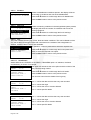
1
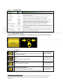
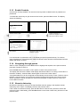
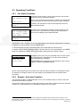
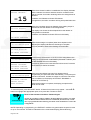
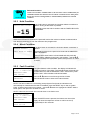
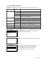
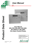
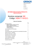
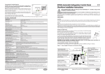
Product Data Sheet
Ex-3000 Series
User Manual for
Ex-3001
Extinguishing Control Panel
The operation and functions
described in the manual are
available from Software Versions
Ex3001_V2_00 onwards.
Table of Contents
1
INTRODUCTION __________________________________________________________ 3
1.1
1.2
1.3
2
Standards ____________________________________________________________ 3
Cautions and Warnings __________________________________________________ 3
Description ___________________________________________________________ 3
OPERATION _____________________________________________________________ 4
2.1
Introduction ___________________________________________________________ 4
2.1.1
Access Levels _____________________________________________________ 4
2.1.2
Front Panel Controls and Indications ____________________________________ 4
2.1.2.1
2.1.2.2
2.1.2.3
2.1.2.4
2.1.2.5
2.1.2.6
2.1.2.7
Display _________________________________________________________________ 4
LED Indications __________________________________________________________ 5
Manual Release Button ____________________________________________________ 6
Control Buttons___________________________________________________________ 6
Menu and Navigation Buttons _______________________________________________ 7
Key-Switches ____________________________________________________________ 7
Buzzer _________________________________________________________________ 7
2.1.3
Enable Controls ____________________________________________________ 8
2.1.4
Navigating through menus ____________________________________________ 8
2.1.5
Numeric data entry __________________________________________________ 8
2.2
Operating Conditions____________________________________________________ 9
2.2.1
Fire Alarm Condition_________________________________________________ 9
2.2.2
Release / Activated Condition _________________________________________ 9
2.2.3
Hold Condition ____________________________________________________ 11
2.2.4
Abort Condition____________________________________________________ 11
2.2.5
Fault Condition ____________________________________________________ 11
2.2.6
Warning Condition _________________________________________________ 12
2.3
Level 1 Menu Functions ________________________________________________ 12
2.3.1
Enable Controls ___________________________________________________ 12
2.3.2
View ____________________________________________________________ 12
2.3.3
LED Test ________________________________________________________ 12
2.4
Level 2 Menu Functions ________________________________________________ 13
2.4.1
View ____________________________________________________________ 13
2.4.1.1
2.4.1.2
2.4.1.3
2.4.1.4
2.4.1.5
2.4.2
2.4.2.1
2.4.2.2
2.4.2.3
2.4.3
2.4.3.1
2.4.3.2
2.4.4
2.4.5
Page 2 of 20
Faults _________________________________________________________________ 13
Disables _______________________________________________________________ 14
Warnings ______________________________________________________________ 14
Log ___________________________________________________________________ 14
Software Versions _______________________________________________________ 15
Test ____________________________________________________________ 15
Zones _________________________________________________________________ 15
Display ________________________________________________________________ 16
Buzzer ________________________________________________________________ 16
Extinguishant Modes _______________________________________________ 17
Mode _________________________________________________________________ 17
Extract ________________________________________________________________ 17
Disable / Enable ___________________________________________________ 18
Date/Time________________________________________________________ 18
1 Introduction
1.1
Standards
The Ex-3001 Gas Extinguishing Control Panel conforms to the following standards:
BS EN12094-1: 2003
Extinguishing Control Device
BS EN54-2: 1998
Control and Indicating Equipment
BS EN54-4: 1998
Power Supply Equipment
BS EN60950: 2000
Safety of information technology equipment
BS EN50130-4: 1996
Product Family Standard
Electromagnetic Compatibility Directive 89/336/EEC (and the amending directive 92/23/EEC)
Low Voltage Directive 73/23/EEC
1.2
Cautions and Warnings
Only Trained service personnel should undertake the Installation,
Programming and Maintenance of this equipment.
1.3
Description
This manual covers the use and how to operate the Ex-3000 Series Extinguishing Control Panels.
Refer to the Installation Manual (Document No. 680-147) for details of installation, programming
and commissioning of the panel.
The Ex-3001 is a Single Flooding Zone Control Panel with up to three detection zone circuits.
The detection zones are compatible with conventional detectors and call points.
Page 3 of 20
2
Operation
2.1 Introduction
These instructions cover the operation and use of the panels.
2.1.1
Access Levels
The panel operation is protected from inadvertent and erroneous misuse by means of four access
levels. These levels are as follows:
•
Level 1
Untrained user
•
Level 2
Authorised User
•
Level 3
Commissioning, Service and Maintenance
•
Level 4
Commissioning, Service and Maintenance – Special Tools Required
This document covers the Level 1 and Level 2 User functions. For details on the installation,
programming and commissioning of the panel, refer to Manual 680-147. Full details are supplied
with any special tools.
•
A Level 1 Untrained User can view the current operational condition of the system and may
MUTE the internal buzzer.
•
A Level 2 Authorised User can view the operational condition of the system and may MUTE
the internal buzzer. In addition, the RESOUND/SOUND ALARMS, SILENCE and RESET
buttons are enabled and access to the Level 2 Menu functions is available. This requires a
password (or key-switch).
•
NOTES: There are up to 4 User ID codes available, each with its own password. The panel
can be configured to automatically cancel access to Level 2 functions after a specified period.
2.1.2
Front Panel Controls and Indications
LCD
R ela y -1
R e la y - 2
F IR E
R e la y
F A U LT
R e la y
R S485
AU X
S u p p ly
ZO NE
- 1 -
ZONE
- 2 -
ZO N E
- 3 -
Navigation Buttons
PS U
C om ms
Manual Release Button
Detection Zone Status
U SB
SUPP LY
SN DR
- 1 -
S NDR
- 2 -
SN DR
- 3 -
MODE
S e le c t
M an ua l H O LD
Tr ig g e r
A B O R T P r e s s u r e V A L V E F L O W A c tu a t o r P R O G
M o n it o r M o n it o r M o n i t o r O u t p u t I n p u t - 1
PR O G
In p u t -2
PROG
I n p ut - 3
P RO G
I n p u t- 4
uP MODE
RUN PROG
R EB O O T
DETECTION ZONES
-1-2-3F IR E
GE NERAL
FIRE
RE LE AS E
IM M INEN T
ABC
FA ULT
DI SA B LE
SOU N DE R FAU LT
!
EX TINGUISHANT
R ELE ASE
PUL L DOW N AN D P RES S BU TTON
EXTIN GUISHANT
R ESET
SIL ENC ED
FA U LT /
TEST/
D IS A B L E
DE F
TIMER H EL D
M U TE
S O UN DER D ISAB LED
GHI
J KL
MNO
PQ RS
TU V
WXY Z
RELE ASED
AB OR T ED
DIS AB LED
FAU LT
MAN UAL
DIS AB LE D
VALVE CLOSE D
B S EN 54-2: 1998 BS EN 5 4-4: 199 8
B S EN 120 94 -1: 2 003
C L A SS-A
S IL E N C E
TE ST
POW ER
SOU ND ER DELAYED
SYS TEM FAU LT
General Status
RESOUND /
SOUND
ALARMS
M ANU AL ON LY
ES C
A U TO +
M A NUA L
ME NU
Control Buttons
Number Buttons
Extinguishant Status
Key-Switch Assembly
2.1.2.1 Display
The LCD along with the LED Indicators shows the operating status of the system. Examples of
the information presented is shown below:
Page 4 of 20
Normal Display
Non-normal Display
Typical Menu Display
[System status]
1 of 1 conditions:
DETECTION ZONE3
OPEN CIRCUIT
22 AUG 2007 16:39:00
[Release status]
UNAFFECTED
[Level 2 Menu]
VIEW
TEST
MODES
DISABLE / ENABLE
EXIT LEVEL 2
Release Imminent
Release Activated
Release Complete
[Release status]
RELEASE IMMINENT..
RELEASE ACTIVATED
00:00:05 Elapsed
RELEASE ACTIVATED
00:00:24 Elapsed
GAS RESET INHIBITED
DISCHARGE COMPLETE
(No Flow Detected)
RESET ALLOWED
SYSTEM NORMAL
-15
The display shows a countdown
timer with the amount of time
remaining before the extinguishant
is released.
.
The display shows the time
elapsed since the extinguishant
release commenced.
2.1.2.2 LED Indications
The LED Status Indications show the basic operational state of the panel and whether the panel
is in a fire alarm, fault, disabled or test condition.
2.1.2.2.1
GENERAL STATUS
Function
Colour
Description
FIRE
Red
Indicates that the system has detected a fire alarm condition
FAULT
Yellow
Indicates that the system has detected a fault condition
DISABLE
Yellow
Indicates that part of the system has been disabled (i.e. isolated)
TEST
Yellow
Indicates that part of the system is in a test condition
POWER
Green
Indicates the presence of power
SILENCED
Yellow
Indicates that the geneal fire alarm sounders have been silenced
SOUNDER FAULT
Yellow
Indicates the presence of a fault in either or both of the general fire alarm sounder wiring
circuits
SOUNDER DISABLED
Yellow
Indicates that either or both of the general fire alarm sounder circuits have been disabled
(i.e. isolated)
DELAYED
Yellow
Not used
SYSTEM FAULT
Yellow
Indicates the presence of a system fault
2.1.2.2.2
DETECTION ZONE STATUS
Function
Colour
Description
FIRE
Red
Indicates that the system has detected a fire alarm condition in the respecitve zone
FAULT/TEST/DISABLE
Yellow
Indicates that the system has (flashing indication) detected a fault condition in the respecitve
zone or (steady indication) that the zone is either in a test state or in a disabled state
Page 5 of 20
2.1.2.2.3
EXTINGUISHANT
Function
Colour
Description
RELEASE IMMINENT
Red
Indicates (flashing) that the release of extinguishant is imminent. The indication will turn to
steady when the signal to release the extinguishant has been activated.
RELEASED
Red
Indicates that the release of extinguishant has occurred and the panel has detected the flow
of the extinguishant released.
TIMER HELD
Yellow
Indicates that the imminent release of extinguishant is temproraily suspended.
ABORTED
Yellow
Indicates that the imminent release of the extinguishant has been aborted.
DISABLED
Yellow
Indicates that the extinguishant release control signal has been disabled. The release of
extinguishant is prevented even if a fire alarm or manual release are present.
FAULT
Yellow
Indicates that the system has detected a fault condition within part of the extinguishing
control device (ECD) circuits. The General Fault LED will also be illuminated.
MANUAL DISABLED
Yellow
Indicates that one or more buttons for manual release have been disabled.
VALVE CLOSED
Yellow
Indicates that the extinguishant is blocked by a manual shut-off valve and that there may be
no extinguishant available to suppress a fire – Ensure immediate remedial action is taken to
address the problem.
MANUAL ONLY
Yellow
Indicates that the extinguishant can only be released by means of a manual release button.
AUTO + MANUAL
Yellow
Indicates that the extinguishant can be released by both the automatic detection of a fire
alarm and by means of a manual release button.
2.1.2.3 Manual Release Button
To manually release the extinguishant, pull down the flap and press the button marked with the
circle.
2.1.2.4
Control Buttons
!
Reset
Press to reset the panel from a fire alarm condition and/ or a
gas release sequence.
Only available with
Level 2 Access.
Mute
Press to mute the internal buzzer.
Available in both
Level 1 and Level 2
Silence 1
1
Press to silence the sounders.
Only available with
Level 2 Access.
Resound / Sound Alarms
Press again to re-activate the sounders.
Press to initiate a manual evacuation and sound the alarms.
Only available with
Level 2 Access.
SILENCE will silence all sounders except for the flooding zone (protected area) sounders when the system is in the
activated state. Once the extinguishant has been released, it is possible to silence the flooding zone sounders.
Page 6 of 20
2.1.2.5
Menu and Navigation Buttons
Press to scroll through Menu Options.
Press to display more information.
Press to scroll through menu Options.
Press to scroll through lists of zones or devices.
Press to confirm entry of numeric information entry.
Press to confirm selection of a menu option.
Press to change some of the configuration options.
Used to enter numbers.
A BC
DEF
WXYZ
GHI
JK L
M NO
PQRS
TU V
W XYZ
ESC
ESC
M ENU
Press to exit the menu functions and return to the
normal display.
Press to show or return to Menu Functions.
MENU
2.1.2.6
Key-Switches
One or two key-switches can be fitted to the panel.
The functions of these are programmable and the installer
will have inserted a label to indicate their use.
Typical uses are:
AUTO + MANUAL / MANUAL ONLY Selection
LEVEL 1 / LEVEL 2 ACCESS Selection
Depending on the key-switch mechanism fitted, the key
may be removable in only one position or removable in
both operating positions.
2.1.2.7 Buzzer
The buzzer produces two different sounds to differentiate between fire alarm conditions and fault /
warning conditions.
Condition
Operation
Fire Alarm
The buzzer operates with a continuous tone.
Fault
The buzzer operates intermittently.
Page 7 of 20
2.1.3
Enable Controls
Controls are normally disabled. If a level 2 Access key-switch is fitted use this in preference to
passwords.
To enable the control keys or gain access to the Level 2, press the Menu button. The display
shows the following:
[CONTROLS DISABLED]
Enter Your Password
Enter Your Password
**
The display prompts for entry of
the password.
Enter the password. As each
number is pressed, an *
character is displayed. Finally,
press the button to confirm.
ENABLE CONTROLS
VIEW
LED TEST
Press the button to select the
‘Enable Controls’ option.
[Level 2 Menu]
VIEW
TEST
EXTINGUISH MODES
DISABLE / ENABLE
EXIT LEVEL 2
.
The display then shows the Level 2
Menu options.
Enter Your Password
Not Recognized!
If the password is incorrect (or if
not entered in time) the above
message is shown.
If a control button is pressed at Level 1, the display prompts for password entry. To continue,
enter the password. If the password is valid, the relevant control function will be activated and the
display will remain at Level 1.
2.1.4
Navigating through menus
When a menu is displayed, use the ÏÐ buttons to highlight the required menu option and then
press the button to select it.
Press the ESC button from within a menu option to return to the previous menu.
The display will revert to the status mode display after 60 seconds on no activity (15 seconds in a
fire alarm condition). Press the Menu button again to return to the menu option.
A programmable timer can be configured to automatically cancel Level 2 access. This time can be
between 1 and 5 minutes. If no buttons are pressed for the timeout period, then Level 2 access
will be cancelled. It will be necessary to re-enter the password to regain access to control and
Level 2 Menu functions.
2.1.5
Numeric data entry
Numbers are entered by moving to the required field, and then typing in the required number,
followed by the button. The display returns to the previous menu.
If the number is entered incorrectly, press the Í button to clear the entry and then re-enter the
required number. Alternatively, press the ESC button to cancel the number entry and return to the
previous menu.
Page 8 of 20
2.2 Operating Conditions
2.2.1
Fire Alarm Condition
[Fire Detected]
FIRE STARTED: ZONE 1
The display shows location / origin of the fire alarm and the total
number of zones in a fire alarm condition.
TOTAL FIRES: 1
If two or more zones enter the fire alarm condition, the display also
shows the location of the last zone to enter a fire alarm condition.
[Release Status]
STAGE-1
In addition, the General Fire LED and the respective Zone Fire
LED will be illuminated.
[Fire Detected]
FIRE STARTED: ZONE 1
LAST FIRE
: ZONE 3
TOTAL FIRES : 2
The status of the extinguishant release is also indicated. If a fire
alarm occurs in a zone that has no effect on the extinguishant
control then the display shows UNAFFECTED.
[Release Status]
STAGE-1
The fire alarm bells / sounders will activate (depending on how they are programmed to respond).
To silence the internal buzzer, press the MUTE button.
To silence the bells, press the SILENCE button (the SILENCED LED will illuminate)2.
To reset the panel, press the RESET button. If a ‘Reset Control’ menu is presented, use the ÏÐ
buttons to highlight the ‘RESET FIRE & GAS’ option, then press the button to select.
[RESET Control]
RESET FIRE & GAS
RESET GAS ONLY
CANCEL RESET
The Reset Control menu may be presented when the reset control
key is pressed (this is dependant on how the control panel has
been configured by the installer).
Use the ÏÐ buttons to highlight the required option, then use the
button to select the highlighted option.
NOTE: If the programming of the panel is such that the release condition is immediately invoked
on detection of a single fire alarm, then the display will immediately show the release status
information.
2.2.2
Release / Activated Condition
The activated condition is established when one or more fire alarms have occurred or when the
manual release button is pressed.
The number of zones, and which zones, that must be in a fire alarm condition before the activated
condition is invoked depends on the installation programming of the panel.
2
SILENCE will silence all sounders except for the flooding zone (protected area) sounders when the system is in the
activated state. Once the extinguishant has been released, it is possible to silence the flooding zone sounders by pressing
the silence button again.
Page 9 of 20
[Release status]
RELEASE IMMINENT..
-15
RELEASE ACTIVATED
00:00:05 Elapsed
When the activated condition is established, the display indicates
that the release is imminent and also shows a countdown timer
with the number of seconds remaining before the extinguishant is
released.
In addition, the Release Imminent LED flashes.
If programmed, the bells / sounders will ring with pulsed alert tone.
When the countdown timer has elapsed, the actuating output is
activated to start the release of the extinguishant.
The display now shows the time elapsed since the release of
extinguishant commenced.
In addition, the Release Imminent LED turns ON steady.
GAS RESET INHIBITED
RELEASE ACTIVATED
10 Seconds Elapsed
When the discharge is complete (either time elapsed or flow
detected) the display indicates the discharge is complete.
DISCHARGE COMPLETE
(No Flow Detected)
It is now possible to silence the flooding zone sounders.
GAS RESET INHIBITED
RELEASE ACTIVATED
10 Seconds Elapsed
RELEASE CONFIRMED
DISCHARGE COMPLETE
GAS RESET INHIBITED
RELEASE ACTIVATED
20 Seconds Elapsed
DISCHARGE COMPLETE
EXTRACT RUNNING
RESET ALLOWED
If confirmed by the detection of the flow of the extinguishant, the
display shows RELEASE CONFIRMED (Released Condition) and
the RELEASED LED turns ON steady.
If previously silenced, the internal buzzer will re-sound. Press the
MUTE button to silence the buzzer.
When the extinguishant has been fully released (and if
programmed), the panel will either automatically, or will prompt for
manual confirmation, activate the output to control the extract fan.
This is indicated on the display as EXTRACT RUNNING or
PRESS to EXTRACT).
When the discharge is complete, the display prompts that the
panel can be reset.
To reset the panel, press the RESET button. A Reset Control menu may appear – use the ÏÐ
buttons to highlight the appropriate option, then press the button to select.
Reset of the Activated Condition / Release Signal.
Section 4.12.2
NOTE: In accordance with EN 12094-1, the ECD shall not permit a reset until
either the RELEASED condition has been established (flow detected) or until
after a programmable time following activation of the mechanism to release the
extinguishant.
NOTE: Depending on programming, the EXTRACT condition may persist after the panel is reset
for up to 120 minutes. This will be indicated on the normal status display (Extract Running).
Page 10 of 20
Section 4.11
2.2.3
Released Condition.
NOTE: In accordance with EN 12094-1, the activated / release condition may be
established without the detection of a fire alarm or manual release. If the panel
detects the release of extinguishant, it will immediately indicate the released
condition.
Hold Condition
COUNTDOWN ON HOLD
(Remove HOLD resume)
If any hold button is activated, the imminent release countdown is
held for as long as the button is pressed.
-15
The display shows the HOLD condition and the TIMER HELD LED
is illuminated.
When the hold button is released, the panel will resume the imminent release countdown either
from the time remaining or from the maximum time programmed.
2.2.4
Abort Condition
RELEASE ABORTED!
PRESS RESET TO REARM
If an abort button is activated, the imminent release countdown is
aborted.
The display prompts for the panel to be reset and the ABORTED
LED is illuminated.
Ensure that the abort button is de-activated and then press the
RESET button. A Reset Control menu may appear – use the ÏÐ
buttons to highlight the appropriate option, then press the button
to select.
2.2.5
Fault Condition
[System status]
1 of 1 conditions:
DETECTION ZONE3
OPEN CIRCUIT
If the panel detects a fault condition, the display will indicate the
number and nature of the faults. The internal buzzer will sound with
an intermittent tone and the GENERAL FAULT LED and any other
specific FAULT LED indications will be illuminated.
[Release status]
UNAFFECTED
Press the MUTE button to silence the internal buzzer.
Press the ÏÐ buttons to scroll through the list of faults.
NOTE: The fault condition is non-latching (except System Fault) and the indications will
automatically be cleared when the fault is remedied. Press the RESET key to clear a System
Fault - a Reset Control menu may appear – use the ÏÐ buttons to highlight the ‘RESET GAS &
FIRE’ option, then press the button to select.
NOTE: If silenced, the buzzer will re-sound when a new fault occurs.
[System status]
1 of 1 conditions:
DETECTION ZONE3
OPEN CIRCUIT
For service call:
01234 567 890
When the MUTE button is pressed, the bottom two lines of the
display will show the telephone number to call for service (if
programmed) for four seconds.
Page 11 of 20
2.2.6
Warning Condition
[System status]
1 of 1 conditions:
PRESSURE MONITOR
OPEN CIRCUIT
If the panel detects an extinguishant warning condition, the display
will indicate the number and nature of the warnings. The internal
buzzer will sound with an intermittent tone and the GENERAL
FAULT LED and any other specific FAULT LED indications will be
illuminated.
[Release status]
UNAFFECTED
Press the ÏÐ buttons to scroll through the list of faults.
Press the MUTE button to silence the internal buzzer.
2.3 Level 1 Menu Functions
2.3.1
Enable Controls
Controls and User Level-2 Menu functions are normally disabled. Refer to Section 2.1.3 for further
details.
2.3.2
View
On selection, the current status of any Faults, Disablements and Warnings along with the history
Log can be shown. These are the same as the Level-2 View function. Refer to Section 2.4.1 for
further details.
2.3.3
LED Test
On selection, the front panel LED Indicators will be illuminated for a short period of time.
Page 12 of 20
2.4 Level 2 Menu Functions
The following table gives a list of the Level 2 Menu Functions and a brief description for each
function.
Menu Option
Sub Menu /
Item
Comments / Description
VIEW
FAULTS
View any current fault conditions recorded.
DISABLES
View any current disablement conditions.
WARNINGS
View any current extinguishant warnings conditions.
LOG
View the history log.
SW VERSIONS
View the software version installed in the extinguishant control panel
and in remote status indicator panels.
ZONES
Test the Detection Zone inputs with/without sounders.
DISPLAY
Test the Display, LED Indicators and Buttons.
BUZZER
Test the Buzzer
MANUAL
Select Manual Only mode / Auto + Manual mode
EXTRACT
Turn on the extract output (if configured)
DISABLE / ENABLE
--
Disable Zone, Sounder, Input and Output circuits and disable
functions. Enable any current disablement conditions
EXIT LEVEL 2
--
Cancels access to Level 2 menu functions and control key functions.
DATE / TIME
--
Allows entry of the current date and time.
COMMISSION
--
Engineer use only – requires separate password.
TEST
EXTINGUISH MODES
2.4.1
View
[View Menu]
FAULTS
DISABLES
WARNINGS
LOG
SW VERSIONS
.
If there are no conditions present, the display will show “Nothing to
Report”.
[Fault Status]
Nothing to Report
2.4.1.1 Faults
[Fault Status]
1 of 3
DETECTION ZONE 1
>SHORT CIRCUIT
DETECTION ZONE 2
>OPEN CIRCUIT
Press the ÏÐ buttons to scroll through the list and press the button to select the required view option.
.
.
If there are fault conditions present, the display will show the
number of conditions and a list of the fault conditions.
Press the ÏÐ buttons to scroll through the list of faults.
Press the ESC button to return to the previous menu.
Page 13 of 20
2.4.1.2 Disables
[Disable List]
Zone 1
DISABLED
Man Release DISABLED
If there are disablement conditions present, the display will show
the number of conditions and a list of the disablements.
Press the ÏÐ buttons to scroll through the list of disablements.
Press the ESC button to return to the previous menu.
2.4.1.3 Warnings
[Warning Status]
1 of 2
VALVE MONITOR INPUT.
>VALVE CLOSED
.
PRESSURE MONITOR
>LOW PRESSURE
If there are warning conditions in the extinguishant system present,
the display will show the number of conditions and a list of the
warning conditions.
Press the ÏÐ buttons to scroll through the list of warnings.
Press the ESC button to return to the previous menu.
2.4.1.4 Log
The panel contains a history log of fires, faults and other conditions. This can be filtered to show
only the fire alarm and trigger events that could result in the release of the extinguishant. In
addition, a total fire alarm count is also available.
[Event Log Menu]
ALL EVENTS
.
FIRES & TRIGGERS
ALARM COUNT
On selection, a menu is presented to select the required view.
Press the ÏÐ buttons to scroll through the list and press the button to select the required view option.
Press the ESC button to return to the previous menu.
2.4.1.4.1 View Events
Select either the ALL EVENTS or the FIRES + TRIGGERS option. On selection, the latest
recorded entry is shown. For example:
[Event Log Viewer]
EVENT:
55/55
The upper two lines show the menu option and the number of the
entry currently being viewed.
20/09/2007 10:21:15
CONTROL PANEL
DETECTION ZONE 3
>OPEN CIRCUIT
Press the ÏÐ buttons to scroll through the list of entries.
[Event Log Viewer]
EVENT:
41/58
Line 1 – shows the date and time the entry was recorded
20/09/2007 09:22:18
USER4
DETECTION ZONE 3
>DISABLE
[Event Log Viewer]
EVENT:
11/58
19/09/2007 12:25:11
CONTROL PANEL
DETECTION ZONE 3
>FIRE ALARM
Page 14 of 20
Press the ESC button to return to the previous menu.
The next four lines show the details of the log entry.
Line 2 – shows the origin
Line 3 – shows the circuit / function affected
Line 4 – shows specific details
Line 1 – shows the date and time the entry was recorded
Line 2 – shows the origin
Line 3 – shows the circuit / function affected
Line 4 – shows specific details
In the above examples:
[1] The control panel recognised and recorded an open-circuit fault condition on the wiring of
Detection Zone 3.
[2] User 4 disabled the operation of, and fault reporting from, Detection Zone 3.
[3] The control panel recognised and recorded a fire alarm condition on Detection Zone 3.
2.4.1.4.2
Alarm Counter
Alarm Counter.
Section 7.13
The Panel records the number of times that the fire alarm condition has
occurred at the panel.
On selection, the display shows the alarm count.
ALARM COUNT
In the example the panel has entered the fire alarm condition 4
times since it was installed.
0000000004
Press the ESC button to return to the previous menu.
The panel increments the count by one each time it changes from the normal condition to indicate
a fire alarm condition. Whilst in the fire alarm condition, and until it is reset, further fire alarm
events do not increment the counter.
2.4.1.5
Software Versions
On selection, the display shows a list containing the panel and any
configured remote status indicators along with the version of
software installed in each device.
[Software Versions]
PANEL : 99.00
RSI-1 : 99.00
RSI-2 : 99.00
RSI-3 : 99.00
RSI-4 : 99.00
2.4.2
Press the ÏÐ buttons to scroll through the list of entries.
Press the ESC button to return to the previous menu.
Test
[Test Menu]
ZONES
DISPLAY
BUZZER
.
Press the ÏÐ buttons to scroll through the list and press the button to select the required test option.
2.4.2.1 Zones
The Test Zones function provides the means to implement a one-person walk test in order to test
specific call points or detectors in one or more zones.
To test the detection zone circuits in accordance with the recommended weekly, monthly and
annual test requirements, select the Test – Zones option. The devices connected to the circuit
can then be tested without activating the extinguishing system and release.
Use the test key supplied for testing manual call points and either a heat source or smoke test
aerosol for testing heat detectors / smoke detectors.
Page 15 of 20
[Zone Test Select]
WITHOUT SOUNDERS
.
WITH SOUNDERS
On selection, the display prompts for whether the sounders / bells
should ring for a short period (about 10 seconds) when the
detection zone enters a test fire alarm condition.
Press the ÏÐ buttons to scroll through the list and press the button to select the required test option.
The display then shows a list of the detection zone circuits.
[Zone Test
ZONE 1
ZONE 2
ZONE 3
Select]
TEST OFF.
TEST OFF
TEST OFF
Press the ÏÐ buttons to scroll through the list and highlight the
required zone circuit.
Press the button to select between TEST OFF and TEST ON.
To leave the Zone Test menu, press the ESC button. If there are still any zones in a test
condition, the display will show the following options: [Zones in Test!]
CANCEL ALL TESTS
CONTINUE TESTS
.
Selecting the CANCEL ALL TESTS option will cancel all zone
tests. The Test LED will then extinguish.
Alternatively, it is possible to leave the Zone Test Function with
one or more Zones still in Test by selecting the CONTINUE
TESTS option. This will enable the inspection or use of other menu
functions and return the display to the normal operating mode.
The Test LED will stay illuminated if this option is selected.
2.4.2.2 Display
The Test Display option checks the operation of all the Indicators and the Graphic Display. All of
the Indicators are turned on and the entire display is shown in reverse.
LCD & KEY TEST
1
During this test, it is possible to test the operation of the
Í,Ï,Ð,Î, and 0-9 buttons. When a button is pressed, it is
indicated on the display. For example:
Press the ESC button to cancel the test and return to the previous
menu.
2.4.2.3 Buzzer
On selection, the buzzer will sound for approximately 10 seconds.
Page 16 of 20
2.4.3
Extinguishant Modes
[Mode Select]
MODE
MANUAL ONLY.
EXTRACT
START?
Press the ÏÐ buttons to scroll through the list and highlight the
required option.
2.4.3.1 Mode
The methods for initiating the release of extinguishant can be selected.
Press the button to select between MANUAL ONLY and AUTO + MANUAL.
In AUTO + MANUAL, the release of extinguishant can be
established if either a manual release button is pressed or if
the one or more of the detection zone circuits is activated
due to detection of smoke.
In MANUAL ONLY, the release of extinguishant can only be
established if one of the manual release buttons is pressed.
SYSTEM NORMAL
22 AUG 2007 16:39:00
SYSTEM NORMAL
(Manual Only Mode)
22 AUG 2007 16:39:00
NOTE: If a key-switch is provided on the front panel, or separately, for this function, then use the
key-switch in preference to the menu option.
2.4.3.2 Extract
If the panel is configured and programmed to provide control of an extract fan then the operation
of the extract fan can be manually controlled via the menu option.
The display is context sensitive and will present different options depending on whether the fan is
on (running) or off.
If the fan is off, the display shows EXTRACT START? – Press the button to start the extract fan
for the pre-programmed time.
If the fan is on, the display shows EXTRACT STOP? – Press the button to stop (turn off) the
extract fan.
NOTE: If a key-switch is provided on the front panel, or separately, for this function, then use the
key-switch in preference to the menu option.
Page 17 of 20
2.4.4
Disable / Enable
[Disabled List]
ZONE1
ENABLED.
ZONE2
ENABLED
ZONE3
ENABLED
Man Release ENABLED
Extinguish ENABLED
Press the ÏÐ buttons to scroll through the list and highlight the
required option.
Press the button to select between ENABLED and DISABLED
conditions. If a circuit or function is disabled, then the General
Disabled LED is illuminated along with any specific circuit /
function disablement LED indicators.
The table below lists all of the items that can be disabled.
Item
Description
Comments
ZONE 1
ZONE 2
ZONE 3
Detection Zones, Zone 1, 2 and 3
Disables any fault reporting on these circuits.
Man Release
Manual Release of the extinguishant.
Prevents the release of extinguishant due to the
activation of any manual release button.
Extinguish
The Output to activate the release of
the extinguishant and Sounder
Circuit 3 (Flooding zone sounders).
Disables any fault reporting on the extinguishing
output circuit and flooding zone sounder circuit.
General Fire Alarm Sounder Output
(circuit 1).
Disables any fault reporting on the sounder-1
circuit.
The zone will not enter the fire alarm condition even
if there is smoke present.
Sounder 1
Prevents the operation of the extinguishing output
and flooding zone sounder circuit even if the release
condition is established.
General fire alarm sounder circuit 1 will remain off
irrespective of the operating condition of the panel.
Sounder 2
General Fire Alarm Sounder Output
(circuit 2).
Disables any fault reporting on the sounder-2
circuit.
General fire alarm sounder circuit 2 will remain off
irrespective of the operating condition of the panel.
Fault Relay
The Fault Relay Output
Prevents the fault relay output from operating.
Fire Relay
The Fire Relay Output
Prevents the fire relay output from operating.
Prog Relays
All other relay control outputs
Prevents all other relay output circuits from
operating.
2.4.5
Date/Time
[Set TIME/DATE]
Press the ÏÐ buttons to scroll through the list and highlight the
required option.
TIME =
DATE =
Enter the required time or date using the number buttons. Enter all
digits including zeros (i.e. 09 then 09 for 9:09 AM).
13:25
29/09/07
After all digits are entered, the time or date is set (if it is a valid time or date).
Page 18 of 20
This page is intentionally left blank.
Page 19 of 20
This page is intentionally left blank.
Document Number:
680-148
Revision:
02
34 Moorland Way : Nelson Park : Cramlington
Northumberland : NE23 1WE
Tel: +44 (0)1670 707 111
Fax: +44 (0)1670 707 222
www.Advel.co.uk Email: Sales@Advel.co.uk
Page 20 of 20